Solectria Renewables PVI 10kW Installation And Operation Manual
208, 240 and 480vac commercial, grid-tied photovoltaic inverter
Hide thumbs
Also See for PVI 10kW:
- Installation and operation manual (6 pages) ,
- Installation and operation manual (40 pages) ,
- Installation and operation manual (37 pages)
Table of Contents
Advertisement
Quick Links
Advertisement
Table of Contents

Subscribe to Our Youtube Channel
Related Manuals for Solectria Renewables PVI 10kW


Summary of Contents for Solectria Renewables PVI 10kW
- Page 1 PVI 10kW / PVI 13kW / PVI 15kW Installation and Operation Manual PVI 10kW PVI 13kW PVI 15kW 208, 240 and 480VAC INSTALLATION AND OPERATION MANUAL Commercial, Grid-Tied Photovoltaic Inverter © 2010, Solectria Renewables LLC Subject to Change DOCR-060002 rev30...
-
Page 2: Important Safety Instructions
Ce manuel contient des instructions importantes qui doivent être suivies lors de l’installation et de l’entretient des onduleurs PVI 10kW / PVI 13kW / PVI 15kW. Afin de réduire les risques de choques électriques et d’assurer une installation et une opération sécuritaires de l’onduleur, les symboles suivants sont utilisés pour identifier les situations dangereuses et les instructions... - Page 3 Before installing or using the PVI 10kW / PVI 13kW / PVI 15kW, please read all instructions and caution markings in this manual and on the PVI 10kW / PVI 13kW / PVI 15kW unit as well as the PV modules.
-
Page 4: Table Of Contents
PVI 10kW / PVI 13kW / PVI 15kW Installation and Operation Manual Table of Contents Introduction………………………………………………………………..………… 5 Installation…………………………………………………………………..……….. 5 Checking for Shipping Damage…………………………………...………. 6 Inverter Mounting.……………………………………………..………….. 6 Electrical Connection Considerations …………………………………..11 Making the Electrical Connections ……………………………………..14 Commissioning the Inverter ……………………………………………………….. 16 Power, GFDI and Error LED Indicators and LCD display..…………………..….…. -
Page 5: Introduction
The PVI 10kW / PVI 13kW / PVI 15kW is a commercial, 3-phase grid-tied PV inverter designed to be inter-connected to the electric utility grid. With this manual the PVI 10kW / PVI 13kW / PVI 15kW can be installed and operated safely. -
Page 6: Checking For Shipping Damage
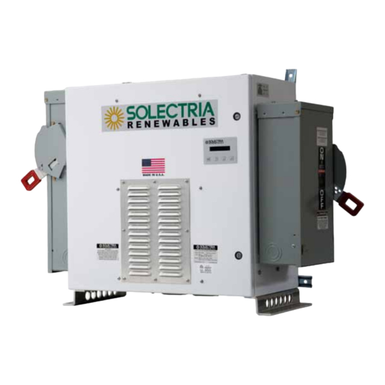
Solectria Renewables. 2.2 – Inverter Mounting The PVI 10kW / PVI 13kW / PVI 15kW inverter is made up of a NEMA 3R (rainproof) industrial enclosure containing electrical and electronic components including transformer, filters, contactor, fusing, a sealed IP65 power & control electronic inverter unit (DMGI245) and AC and DC disconnects mounted on the sides of the main enclosure. - Page 7 PVI 10kW / PVI 13kW / PVI 15kW Installation and Operation Manual NOTE: The 380 lb. weight of the inverter will exert as much as 100 lbs. per bolt on the 4 wall mounts. Tension on the top bolts could also be 100 lbs. Make sure an appropriate safety margin is used for both shear and tension of wall mounting bolts, anchors or other attachments.
- Page 8 PVI 10kW / PVI 13kW / PVI 15kW Installation and Operation Manual The ambient temperature must be between –25 C and +50 C for full power, continuous operation. The inverter will automatically reduce power or shut down to protect itself if ambient air temperature rises above 50 ...
- Page 9 PVI 10kW / PVI 13kW / PVI 15kW Installation and Operation Manual Fig. 2.2a PVI 10kW / PVI 13kW / PVI 15kW Mounting Diagram with standard side-facing disconnects Fig. 2.2b PVI 10kW / PVI 13kW / PVI 15kW with optional forward-facing disconnect option...
- Page 10 PVI 10kW / PVI 13kW / PVI 15kW Installation and Operation Manual Fig. 2.2c PVI 10kW / PVI 13kW / PVI 15kW Mounting Diagram with standard side-facing disconnects DOCR-060002 rev30 July 7, 2010...
-
Page 11: Electrical Connection Considerations
PVI 10kW / PVI 13kW / PVI 15kW Installation and Operation Manual 2.3 – Electrical Connection Considerations PVI 10 kW PVI 13 kW PVI 15 kW Fig. 3 Simplified electrical connection diagram Main enclosure Wall Mounts LED indicators and with integrated... - Page 12 PVI 10kW / PVI 13kW / PVI 15kW Installation and Operation Manual WARNING: All electrical installations shall be done in accordance with all local electrical codes and the National Electrical Code, Canadian Electrical Code, ANSI/NFPA 70. WARNING: The grounded DC photovoltaic connection (typically the negative DC connection) is bonded to ground within the inverter through the ground fault detection and interruption circuit (GFDI).
- Page 13 PVI 10kW / PVI 13kW / PVI 15kW Installation and Operation Manual DC Wiring: For the DC wiring without an integrated fused PV combiner, two conductors are required (one for the grounded conductor and one for the ungrounded conductor) plus additional conductors for grounds (see grounding section below).
-
Page 14: Making The Electrical Connections
WARNING: Please follow all applicable local codes. The inverters meet and are certified to all UL1741 and IEEE1547 requirements. Solectria Renewables does not endorse any of the connections discussed below. The following are recommended courses of action that must be approved by local building officials before any connections are made. - Page 15 PVI 10kW / PVI 13kW / PVI 15kW Installation and Operation Manual WARNING: Before making the DC connections at the DC disconnect, check the correct polarity and admissible DC voltage between the grounded and ungrounded DC connections. WARNING: The wiring connections of the inverter to the DC voltage from the PV strings...
-
Page 16: Commissioning The Inverter
The inverter operates automatically without the need for user interaction or maintenance. The PVI 10kW / PVI 13kW / PVI 15kW inverter automatically starts back feeding 3-phase AC power into the grid every morning as the sun rises, as soon as sufficient DC voltage and PV power is available. The inverter DSP runs through various checks before going online with the grid and feeding power into the grid. -
Page 17: Power, Gfdi And Error Led Indicators And Lcd Display
“Description and Location of Components”. Turn off AC & DC power and locate, check and replace the GFDI fuse with a 3/4A midget fuse 500V DC or 600V DC rated such as Solectria Renewables P/N KLK ¾ or KLKD 3/4, or Bussmann, KLK-3/4 or KLKD-3/4. Fig. 5 LED indicators... - Page 18 PVI 10kW / PVI 13kW / PVI 15kW Installation and Operation Manual LED indicator Operating condition Description green: standby (night) input voltage < 125 VDC yellow: red: green: initialization unit is being initialized yellow: red: green: stop Input voltage low < 210V...
- Page 19 PVI 10kW / PVI 13kW / PVI 15kW Installation and Operation Manual green: Contactor Failure Contactor timer run out before successful open or close yellow: (one blink) red: green: Vsense Failure DSP board cannot communicate with vsense board yellow: (two blinks)
-
Page 20: Lcd Display
PVI 10kW / PVI 13kW / PVI 15kW Installation and Operation Manual 4.2 LCD Display Button Description ESC: To move up a level from the current menu. : To scroll up/down the individual menu items : To enter into selected menu. - Page 21 PVI 10kW / PVI 13kW / PVI 15kW Installation and Operation Manual Measurements Menu This displays the data retrieved from the inverter. Use the buttons to move up and down the list: o AC Energy o AC Power o AC Voltage...
-
Page 22: Troubleshooting & Opening The Main Enclosure
Installation and Operation Manual 5 – Trouble Shooting The PVI 10kW / PVI 13kW / PVI 15kW is designed, produced and rigorously tested for long life and reliability in a wide range of climate conditions, voltage and power levels. With a properly shipped, sited, mounted, wired and tested installation, the integrated PVI 10kW / PVI 13kW / PVI 15kW inverter unit should give many years of trouble-free and maintenance-free service. - Page 23 If at some point it is determined that the unit or any part of the unit should be shipped to Solectria Renewables for repair or replacement, be sure to get an RMA# from Solectria Renewables and use the same packing method as when it was shipped to you, or request instruction on packing and/or packing materials from Solectria Renewables to help insure a safe shipment.
- Page 24 PVI 10kW / PVI 13kW / PVI 15kW Installation and Operation Manual Fig. 6 Description and location of components DOCR-060002 rev30 July 7, 2010...
-
Page 25: Warranty Information And Liability
Duration of a Solectria Renewables Warranty Period: The warranty period is 60 months from the date of purchase of the PVI 10kW / PVI13kW / PVI15kW by the end user or 64 months after the delivery date from Solectria Renewables to distributor or dealer/installer, whichever is shorter. - Page 26 Installation and Operation Manual What will Solectria Renewables do? Solectria Renewables will, at its option, repair or replace the defective product free of charge, provided that you notify Solectria Renewables of the product defect within the Warranty Period for your product, and provided that Solectria Renewables, through inspection, establishes the existence of such a defect and that it is covered by the Limited Warranty.
- Page 27 These warranties do not apply to and Solectria Renewables will not be responsible for any defect in or damage a) The product, if it has been misused, neglected, improperly installed, physically damaged or altered, either internally or externally, or damaged from improper use or use in an unsuitable environment;...
- Page 28 AS A RESULT OF ANY USE, MISUSE OR ABUSE, OR THE (IN-) CORRECT INSTALLATION, INTEGRATION OR OPERATION OF THE PRODUCT. Solectria Renewables neither assumes nor authorizes any other person to assume for it any other liability in connection with the repair or replacement or the Product.
-
Page 29: Return Material Authorization Policy
2) Include the following: a. The RMA number supplied by Solectria Renewables, LLC clearly marked on the outside of the box b. A return address to which the unit can be shipped. Post office boxes are not acceptable. -
Page 30: Technical Data
Installation and Operation Manual 7 – Technical Data Technical Information and specifications – see appendix for complete PVI 10KW / PVI 13KW / PVI 15KW data sheet Input (DC) from PV array: Maximum open circuit voltage of PV array: 475V DC ... - Page 31 Output to AC grid connection: The PVI 10KW / PVI 13KW / PVI 15KW is designed to feed power into a standard 60Hz, 3-phase AC utility service or AC provided within a facility by a step down transformer of not less than 15kVA. As required by local codes, there must be a dedicated 3-phase circuit breaker for the PV inverter connection.
- Page 32 PVI 10kW / PVI 13kW / PVI 15kW Installation and Operation Manual Output (AC) specifications for PVI 10KW / PVI 13KW / PVI 15KW Inverter: Nominal and Maximum output power of the PVI 10KW 10.0 kW AC of the PVI 13KW 13.2 kW AC...
- Page 33 Fig. 11 Output power of PVI 13KW (example) 0.00 5.00 10.00 15.00 AC Power (kW AC) Fig. 12 PVI 10kW / PVI 13kW / PVI 15kW peak efficiency plot at 280VDC input and 25C ambient temperature. DOCR-060002 rev30 July 7, 2010...
-
Page 34: Appendices
PVI 10kW / PVI 13kW / PVI 15kW Installation and Operation Manual Appendix A – PVI 10kW / PVI 13kW / PVI 15kW Data Sheet Link to brochure: http://www.solren.com/downloads/PVI_13KW.pdf Appendix B –PV string sizing Visit our interactive string sizing tool: http://www.solren.com/stringSizing.html... -
Page 35: Appendix D: Ul 1741 Listing Letter
PVI 10kW / PVI 13kW / PVI 15kW Installation and Operation Manual Appendix D – UL1741/IEEE1547 Certification Letter DOCR-060002 rev30 July 7, 2010...
Need help?
Do you have a question about the PVI 10kW and is the answer not in the manual?
Questions and answers