Solectria Renewables PVI 10KW Installation And Operation Manual
Commercial, grid-tied photovoltaic inverter
Hide thumbs
Also See for PVI 10KW:
- Installation and operation manual (6 pages) ,
- Installation and operation manual (35 pages) ,
- Installation and operation manual (37 pages)
Table of Contents

Subscribe to Our Youtube Channel
Related Manuals for Solectria Renewables PVI 10KW


Summary of Contents for Solectria Renewables PVI 10KW
- Page 1 PVI 10KW / PVI 13KW / PVI 15KW Installation and Operation Manual PVI 10KW PVI 13KW PVI 15KW INSTALLATION AND OPERATION MANUAL Commercial, Grid-Tied Photovoltaic Inverter © 2010, Solectria Renewables LLC Subject to Change DOC-020028 rev 028...
-
Page 2: Important Safety Instructions
Ce manuel contient des instructions importantes qui doivent être suivies lors de l’installation et de l’entretient des onduleurs PVI 10KW / PVI 13KW / PVI 15KW. Afin de réduire les risques de choques électriques et d’assurer une installation et une opération sécuritaires de l’onduleur, les symboles suivants sont utilisés pour identifier les situations dangereuses et les instructions... - Page 3 Before installing or using the PVI 10KW / PVI 13KW / PVI 15KW, please read all instructions and caution markings in this manual and on the PVI 10KW / PVI 13KW / PVI 15KW unit as well as the PV modules.
-
Page 4: Table Of Contents
PVI 10KW / PVI 13KW / PVI 15KW Installation and Operation Manual Table of Contents Introduction………………………………………………………………..………… 5 Installation…………………………………………………………………..……….. 6 Checking for Shipping Damage…………………………………...………. 6 Inverter Mounting.……………………………………………..………….. 6 Electrical Connection and Connection to Electrical Utility Grid and Surge/Lightning Protection. ……………………………………………..11 Commissioning the Inverter PV System …………………………………………….. -
Page 5: Introduction
The PVI 10KW / PVI 13KW / PVI 15KW is a commercial, 3-phase grid-tied PV inverter designed to be inter-connected to the electric utility grid. With this manual the PVI 10KW / PVI 13KW / PVI 15KW can be installed and operated safely. This installation guide is used as reference for the commissioning and as a guideline on how to use the inverter most effectively. -
Page 6: Installation
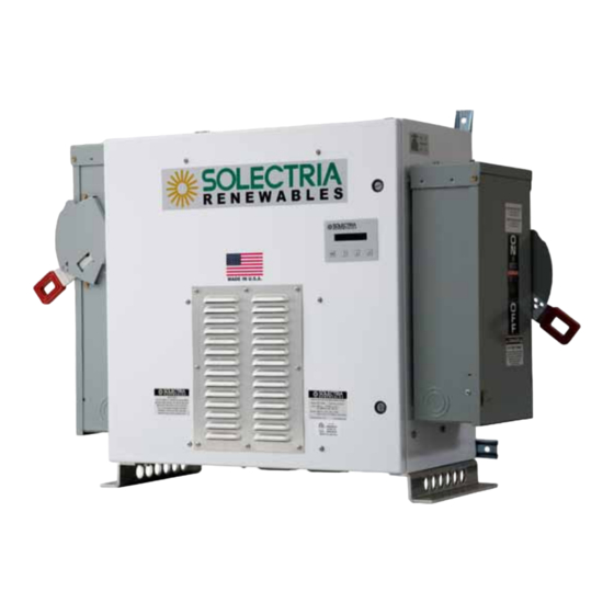
Solectria Renewables. 2.2 Inverter Mounting PVI 10KW / PVI 13KW / PVI 15KW inverter is made up of a NEMA 3R (rainproof) industrial enclosure containing electrical and electronic components including transformer, filters, contactor, fusing, a sealed IP65 power & control electronic inverter unit (DMGI245) and AC and DC disconnects mounted on the sides of the main enclosure. - Page 7 PVI 10KW / PVI 13KW / PVI 15KW Installation and Operation Manual Notes regarding mounting and placement of the inverter. Criteria for device mounting: • Because the power electronics is in an IP65 sealed enclosure within the NEMA 3R main enclosure, the inverter can be mounted outdoors.
- Page 8 PVI 10KW / PVI 13KW / PVI 15KW Installation and Operation Manual • The cooling air exhausts at the bottom of the unit. Nothing should block the 2” clear space under the enclosure defined by the 2” tall mounting feet.
- Page 9 PVI 10KW / PVI 13KW / PVI 15KW Installation and Operation Manual Fig. 2.2a PVI 10KW / PVI 13KW / PVI 15KW Mounting Diagram (standard side-facing disconnects) Fig. 2.2b PVI 10KW / PVI 13KW / PVI 15KW with forward-facing disconnect option...
- Page 10 PVI 10KW / PVI 13KW / PVI 15KW Installation and Operation Manual Fig. 2.2c PVI 10KW / PVI 13KW / PVI 15KW Mounting Diagram (standard side-facing disconnects) Mounting Details Using the mounting diagram Fig. 2.2 (a & c), choose whether floor/roof, wall or stand mounting will be used.
-
Page 11: Electrical Connection And Connection To Electrical Utility Grid And Surge/Lightning Protection
PVI 10KW / PVI 13KW / PVI 15KW Installation and Operation Manual NOTE: Always use all 4 mounting tabs if wall mounted. NOTE: The nearly 380 lb. weight of the inverter will exert as much as 100 lbs. per bolt on the 4 wall mounts. Tension on the top bolts could also be 100 lbs. - Page 12 PVI 10KW / PVI 13KW / PVI 15KW Installation and Operation Manual Main enclosure Wall Mounts LED indicators and with integrated GFDI warning label inverter, transformer filters and contactor Fused AC Disconnect LCD Display & Keypad Warning Label disconnect with fused...
- Page 13 PVI 10KW / PVI 13KW / PVI 15KW Installation and Operation Manual AWG copper conductor wire, and 4 AWG copper ground wire can be used, but verify that any wire size choices meet NEC (Canadian Electrical Code) requirements) For DC/PV wiring with the integrated, fused PV combiner (with 10-15 Amp fuses),...
- Page 14 PVI 10KW / PVI 13KW / PVI 15KW Installation and Operation Manual (Canadian Electrical Code) requirements. This conductor should be terminated on the ground bar in the AC disconnect. If required, an additional lug of the appropriate size for the grounding electrode conductor can be added in the AC disconnect and bonded to the existing ground bar in the disconnect in a code compliant manner.
- Page 15 PVI 10KW / PVI 13KW / PVI 15KW Installation and Operation Manual PV ground/frame connections 10-4 PV negative (-), up AWG copper wire to 7 connections (a larger lug can be 12-8 AWG copper added if required) wire torque to 35...
- Page 16 Connection Wiring To Electrical Utility Grid The PVI 10KW / PVI 13KW / PVI 15KW must be connected to the grid with 3 conductors and an AC equipment grounding conductor. A 50A breaker is recommended for the dedicated PV system circuit breaker for the PVI 13KW-208VAC (or 240VAC) versions.
- Page 17 PVI 10KW / PVI 13KW / PVI 15KW Installation and Operation Manual This is because with larger wires, the AC voltages at the inverter will be closest to the voltages at the building’s circuit panel. Connection of the PV-panels to the DC disconnect enclosure with or without integrated fused PV combiner WARNING: Follow PV module manufacturer’s directions.
-
Page 18: Commissioning The Inverter Pv System
PVI 10KW / PVI 13KW / PVI 15KW Installation and Operation Manual of the disconnect will also remain live after the disconnect has been shut off until 60 seconds after the LEDs turn off, as electrolytic DC bus capacitors in the inverter discharge. -
Page 19: Power, Gfdi And Error Led Indicators And Lcd Display
• Verify the proper CLOCKWISE phase sequence at the “line” side terminals of the AC disconnect • Turn on the PVI 10KW / PVI 13KW / PVI 15KW inverter’s 3-phase AC disconnect • If equipped with Fat Spaniel Inverter-Direct monitoring option, refer to Fat Spaniel PV2Web Installation Manual for gateway startup sequence before turning on inverter’s DC... - Page 20 GFDI fuse with a 0.75A midget fuse 500V DC or 600V DC rated such as Solectria Renewables P/N KLK ¾ or KLKD 3/4, or Bussmann, KLK-3/4 or KLKD-3/4. Fig. 8. The view from right-hand side of inverter above DC (PV) disconnect (LED indicator...
- Page 21 PVI 10KW / PVI 13KW / PVI 15KW Installation and Operation Manual LED indicator Operating condition Description green: standby (night) input voltage < 125 VDC yellow: red: green: initialization unit is being initialized yellow: red: green: stop Input voltage low < 325V...
- Page 22 PVI 10KW / PVI 13KW / PVI 15KW Installation and Operation Manual green: Contactor Failure Contactor timer run out before successful open or close yellow: (one blink) red: green: Vsense Failure DSP board cannot communicate with vsense board yellow: (two blinks)
-
Page 23: Lcd Display
PVI 10KW / PVI 13KW / PVI 15KW Installation and Operation Manual 4.2 LCD Display Button Description ESC: To move up a level from the current menu. ↑↓: To scroll up/down the individual menu items ↵: To enter into selected menu. - Page 24 PVI 10KW / PVI 13KW / PVI 15KW Installation and Operation Manual Measurements Menu This displays the data retrieved from the inverter. Use the ↑↓ buttons to move up and down the list: AC Energy AC Power AC Voltage AC Current (3 phase average) DC Voltage Pressing ESC will take the screen back to the start menu.
-
Page 25: Troubleshooting & Opening The Main Enclosure
1 pulse = 10 WH 5 Trouble Shooting The PVI 10KW / PVI 13KW / PVI 15KW is designed, produced and rigorously tested for long life and reliability in a wide range of climate conditions, voltage and power levels. With a properly shipped, sited, mounted, wired and tested installation, the integrated PVI 10KW / PVI 13KW / PVI 15KW inverter unit should give many years of trouble-free and maintenance-free service. - Page 26 If at some point it is determined that the unit or any part of the unit should be shipped to Solectria Renewables for repair or replacement, be sure to get an RMA# from Solectria Renewables and use the same packing method as when it was shipped to you, or request instruction on packing and/or packing materials from Solectria Renewables to help insure a safe shipment.
- Page 27 PVI 10KW / PVI 13KW / PVI 15KW Installation and Operation Manual Opening the Main Enclosure Normally the main enclosure (or disconnects) will not have to be opened for any reason by the user. If opening the unit is necessary follow these guidelines: WARNING: The inverter should only be opened by qualified service technician.
- Page 28 PVI 10KW / PVI 13KW / PVI 15KW Installation and Operation Manual Fig. 9 Description and location of components DOC-020028 rev 028...
-
Page 29: Warranty Information And Liability
Duration of a Solectria Renewables Warranty Period: The warranty period is 60 months from the date of purchase of the PVI 10KW / PVI13KW / PVI15KW by the end user or 64 months after the delivery date from Solectria Renewables to distributor or dealer/installer, whichever is shorter. - Page 30 All replaced products and all parts removed from repaired products become the property of Solectria Renewables. Solectria Renewables will attempt to repair the unit within a reasonable time period (there is no reimbursement for lost energy production.)
- Page 31 The product, if repairs have been done to it other than by Solectria Renewables or authorized, trained service personnel; d) The product, if it is used as a component part of a product expressly warranted by another manufacturer;...
- Page 32 ARISING FROM OR AS A RESULT OF ANY USE, MISUSE OR ABUSE, OR THE (IN-) CORRECT INSTALLATION, INTEGRATION OR OPERATION OF THE PRODUCT. Solectria Renewables neither assumes nor authorizes any other person to assume for it any other liability in connection with the repair or replacement or the Product.
-
Page 33: Return Material Authorization Policy
2) Include the following: a. The RMA number supplied by Solectria Renewables, LLC clearly marked on the outside of the b. A return address to which the unit can be shipped. Post office boxes are not acceptable. -
Page 34: Technical Data
Installation and Operation Manual 7 Technical Data Technical Information and specifications – see appendix for complete PVI 10KW / PVI 13KW / PVI 15KW data sheet Input (DC) from PV array: • Maximum open circuit voltage of PV array: 475V DC... - Page 35 Output to AC grid connection: The PVI 10KW / PVI 13KW / PVI 15KW is designed to feed power into a standard 60Hz, 3-phase 208V AC utility service or 208V AC provided within a facility by a step down transformer of not less than 15kVA.
- Page 36 600 VAC 528-660 V 528-660 V 528-660 V Output (AC) specifications for PVI 10KW / PVI 13KW / PVI 15KW Inverter: Nominal and Maximum output power of the PVI 10KW 10.0 kW AC of the PVI 13KW 13.2 kW AC of the PVI 15KW 15.0 kW AC...
- Page 37 PVI 10KW / PVI 13KW / PVI 15KW Installation and Operation Manual Other specifications: DC combiner-fuse enclosure 8/10/12/15A fuses available (Optional) 5-7 pole, NEMA 3R, TVSS DC Disconnect (Integral) Break load rated, NEMA 3R Ambient Temperature to 50 Storage Temperature...
- Page 38 10.00 15.00 AC Power (kW AC) Fig. 13. PVI 10KW / PVI 13KW / PVI 15KW peak efficiency plot at 280VDC input and 25C ambient temperature. Pin assignment RS232 / RS485 (optional) and Internet Gateway connection 1 RS232 TXD 2 RS232 RXD...
-
Page 39: Appendices
PVI 10KW / PVI 13KW / PVI 15KW Installation and Operation Manual Appendix A – PVI 10KW / PVI 13KW / PVI 15KW Data Sheet Link to brochure: http://www.solren.com/downloads/PVI_13KW.pdf Appendix B – Example PV string sizing chart(s) Link: http://www.solren.com/downloads/PVI_13KWString.pdf The charts below are simplified string sizing examples. Please use the charts on the website for complete charts for use across the country. -
Page 40: Appendix D: Ul 1741 Listing Letter
PVI 10KW / PVI 13KW / PVI 15KW Installation and Operation Manual Appendix D – UL1741/IEEE1547 Certification Letter DOC-020028 rev 028...
Need help?
Do you have a question about the PVI 10KW and is the answer not in the manual?
Questions and answers