
Subscribe to Our Youtube Channel
Related Manuals for Solectria Renewables SGI 225


Summary of Contents for Solectria Renewables SGI 225
- Page 1 SGI 225 SGI 250 SGI 266 SGI 300 SGI 500 SGI 500PE INSTALLATION AND OPERATION MANUAL Revision E © 2012, Solectria Renewables LLC...
- Page 2 Installation and Operation Manual (Rev E) SGI Series Inverters IMPORTANT REGISTRATION AND WARRANTY INFORMATION For warranty to become active, this inverter must be registered. To activate warranty and register inverter, please visit the link below. www.solren.com/registration...
- Page 3 SGI Series Inverters IMPORTANT SAFETY INSTRUCTIONS In this manual “inverter” or “inverters” refers to the inverter models: SGI 225, SGI 250, SGI 266, SGI 300, SGI 500PE and SGI 500 unless one of the specific models is noted. This manual contains important instructions that shall be followed during installation and maintenance of the SGI inverter.
- Page 4 All electrical installations shall be performed in accordance with the local, American and Canadian electrical codes. The inverter contains no user serviceable parts. Please contact Solectria Renewables or a Solectria Renewables authorized system installer for maintenance. See Appendix C for Solectria Renewables contact information and authorized system installers.
-
Page 5: Table Of Contents
Installation and Operation Manual (Rev E) SGI Series Inverters Table of Contents Introduction ............................1 Site Preparation and Inverter Placement ..................4 Inverter Positioning ........................6 Leveling the Inverter ........................6 Mounting Details ........................... 7 DC and AC Wire Entry Points ......................8 Installation ............................ - Page 6 Internal Circuit Diagram ......................52 10.0 Appendices ............................53 10.1 Appendix A – SGI 225, SGI 250, SGI 266, SGI 300, SGI 500PE and SGI 500 Data Sheet ....53 10.2 Appendix B – String Sizing Tool ....................53 10.3 Appendix C –...
-
Page 7: Introduction
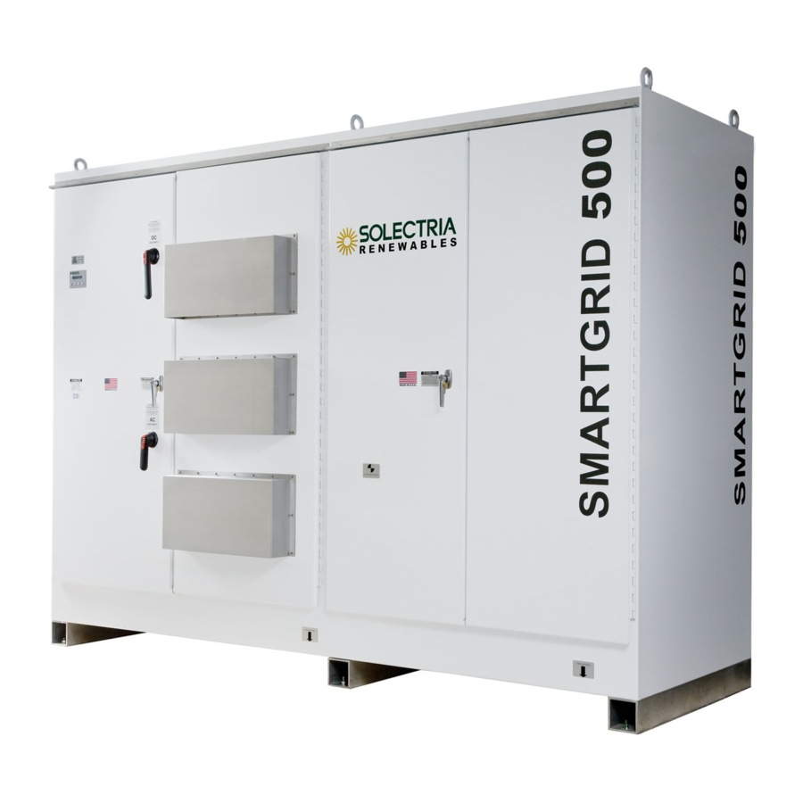
Installation and Operation Manual (Rev E) SGI Series Inverters 1.0 Introduction The Smart Grid inverters (SGI) are commercial, three-phase grid-tied PV inverters designed to be interconnected to the electric utility grid. By following this manual the inverter can be installed and operated safely. This installation guide is used as a reference for the commissioning process and as a guideline on how to use the inverter most effectively. - Page 8 Installation and Operation Manual (Rev E) SGI Series Inverters DC disconnect Warning label Lift eyes switch LEDs LCD display and keypad Nameplate, specs and ETL, UL1741 / IEEE1547 / CSA certification labels Cooling air intake Left side of enclosure Right side of enclosure contains integrated inverter, contains isolation filters and contactor...
- Page 9 Installation and Operation Manual (Rev E) SGI Series Inverters Exhaust air vents Figure 1.3 – The SGI Inverter (Rear) DOCR-060371...
-
Page 10: Site Preparation And Inverter Placement
Installation and Operation Manual (Rev E) SGI Series Inverters 2.0 Site Preparation and Inverter Placement The inverter is comprised of a rainproof industrial enclosure containing electrical and electronic components and AC and DC integrated disconnecting means. NOTE: If the inverter is mounted outside, ensure that the enclosure doors remain closed during the installation process in case of rain or snow. - Page 11 SGI 500, 500PE 6980 lbs. 8000 lbs SGI 300, 266, 250 5650 lbs. 6000 lbs SGI 225 5170 lbs 6000 lbs Table 2.1 – Weight and Required Fork Lift Capacity The ambient temperature must be between –40 C and +50 C for full power, continuous operation.
-
Page 12: Inverter Positioning
Installation and Operation Manual (Rev E) SGI Series Inverters Inverter Positioning Correct mounting position for the inverter is vertical with the mounting feet on the floor. This diagram shows the basic inverter footprint dimensions: Figure 2.1 – SGI Series Dimensions (Top View) Leveling the Inverter The inverter must be mounted on a flat and level plane in order for proper operation of the doors and integral DC disconnect and AC breaker. -
Page 13: Mounting Details
Installation and Operation Manual (Rev E) SGI Series Inverters Mounting Details The inverter includes mounting feet with 6 holes (1/2”, 12mm diameter) on a rectangular pattern for attaching the inverter. Note that the outer 4 mounting holes are 2” inside each corner of the main inverter enclosure. -
Page 14: Dc And Ac Wire Entry Points
Installation and Operation Manual (Rev E) SGI Series Inverters DC and AC Wire Entry Points AC and DC wiring must enter through the provided conduit cutout in the bottom of the inverter enclosure or through the alternate conduit entries. Alternative locations are the left side for DC and back panel for AC. - Page 15 Installation and Operation Manual (Rev E) SGI Series Inverters Fig 2.5 – Alternate DC Conduit Entry Locations Figure 2.6 – Alternate AC Conduit Entry Location DOCR-060371...
-
Page 16: Installation
Please inspect the inverter thoroughly after it is delivered. If any damage is seen please immediately notify the shipping company to make a claim. If there is any question about potential shipping damage, contact Solectria Renewables. Photos of the damage may be helpful in documenting potential shipping damage. -
Page 17: Inverter Mounting
Use an 8,000lb capable forklift for the SGI 500and SGI 500PE or 6,000lb capable forklift for the SGI 225-300 if lifting from the bottom. The forks should be set to an inside spacing so they fit just to the left of the inverter's 4” x 4" aluminum tube feet. - Page 18 Installation and Operation Manual (Rev E) SGI Series Inverters Figure 3.1 – Forklift Lifting Positions Use positions A when lifting or moving the inverter while attached to the pallet Use positions B when lifting or moving the inverter removed from the pallet Note that the lifting diagrams show the inverter being lifted while mounted on the shipping pallet.
- Page 19 Installation and Operation Manual (Rev E) SGI Series Inverters Figure 3.2 – Preferred Straight-Chain Lifting Method DOCR-060371...
- Page 20 Installation and Operation Manual (Rev E) SGI Series Inverters 4’ Minimum Figure 3.3 – Minimum Requirements for Eyebolt Lifting DOCR-060371...
- Page 21 Installation and Operation Manual (Rev E) SGI Series Inverters 20’ Minimum Figure 3.4 – Marginal Lifting Method DOCR-060371...
- Page 22 Installation and Operation Manual (Rev E) SGI Series Inverters Less than 20’ Figure 3.5 – Improper Lifting Method DOCR-060371...
-
Page 23: Dc Connections From The Pv Array And Ac Connections To The Electrical Utility Grid
Installation and Operation Manual (Rev E) SGI Series Inverters 4.0 DC Connections from the PV Array and AC Connections to the Electrical Utility Grid WARNING: All electrical installations shall be performed in accordance with all local electrical codes and the National Electrical Code, Canadian Electrical Code for Canada and NFPA 70. -
Page 24: Equipment Grounding Conductor (Egc)
Installation and Operation Manual (Rev E) SGI Series Inverters Equipment Grounding Conductor (EGC) The ground bond plate is also equipped with a number of provisions for equipment grounding conductors. In most instances, these will be used for the equipment grounds originating at the combiner boxes used to feed the subcombiner positions within the inverter. -
Page 25: Dc Subcombiner Wiring
Installation and Operation Manual (Rev E) SGI Series Inverters DC Subcombiner Wiring WARNING: Before terminating AC or DC conductors at the inverter, ensure that the conductors are deenergized by turning any AC and DC disconnects off, building AC source circuits or breakers off and disconnect the PV module strings (or ensure that the modules are covered). - Page 26 SGI 500, 500PE: 32 positions 110 – 200A 600VDC fuses 225 – 400A 600VDC fuses 70 – 100A 600VDC fuses SGI 225-300: 12 positions SGI 225-300: 6 positions SGI 225-300: 24 positions 110 – 200A 600VDC fuses 225 – 400A 600VDC fuses 70 –...
- Page 27 SGI 500, SGI 500PE: 32 positions 8 lugs positions 8 lugs (two wires per lug) 16 lugs (double lugs) SGI 225-300: 6 positions SGI 225-300: 12 positions 6 lugs SGI 225-300: 24 positions 6 lugs (two wires per lug) 12 lugs (double lugs)
- Page 28 SGI 500, SGI 500PE: 8 positions SGI 500, SGI 500PE: 16 positions 225 – 400A 600VDC breakers 110 – 200A 600VDC breakers SGI 225-300: 6 positions SGI 225-300: 12 positions 225 – 400A 600VDC breakers 110 – 200A 600VDC breakers...
- Page 29 SGI 500, SGI 500PE: 8 positions SGI 500, SGI 500PE: 16 positions 8 lugs 8 lugs (two wires per lug) SGI 225-300: 6 positions SGI 225-300: 12 positions 6 lugs 6 lugs (two wires per lug) Cu or Al Conductors Cu or Al Conductors Max.
-
Page 30: Dc Ground Fault Detection And Interruption
Figure 4.3 – Operating Positions of GFDI Breaker DC Ground Fault Current Pickup Maximum Trip Time SGI 225/250 SGI 266/300/500PE/ 500 Table 4.5 – DC GFDI Specifications WARNING: In the event of a ground fault, DO NOT TOUCH any equipment (including, but not limited to: the inverter, the PV array disconnects, the PV array combiners, the PV panels, the PV racking system). -
Page 31: Ac Wiring
AC phase wiring to the onsite electrical service or grid connection. The integrated breaker will have different ratings depending on the inverter model. Model Ampere Rating Interrupt Rating 100% Rated SGI 225-480VAC 400A 25 kAIC SGI 250-480VAC 400A 35 kAIC... - Page 32 Voltage drop and other considerations may dictate that larger wire sizes be used. Maximum Number of Minimum Maximum Model Terminals per Phase Wire Size Wire Size Terminal Torque SGI 225-480VAC 3/0AWG 500kcmil 275 in-lbs SGI 250-480VAC 3/0AWG 500kcmil 275 in-lbs SGI 266-480VAC 3/0AWG...
- Page 33 The transformer’s neutral bar has also been designed with a set of holes to allow for various field connections such as a box lug or a crimped lug. SGI 500/PE Neutral Routing Path SGI 225-300 Neutral Routing Path SGI 500/500PE Neutral Landing SGI 225-300 Neutral Landing Locations...
-
Page 34: Ac Ground Fault Detection
Installation and Operation Manual (Rev E) SGI Series Inverters AC Ground Fault Detection The SGI series of inverters are not equipped with AC ground fault protection. When AC ground fault protection is used on the onsite electrical service, determine if the ground fault device is listed to be backfed. - Page 35 Installation and Operation Manual (Rev E) SGI Series Inverters Begin by locating a set of terminal blocks that are identified as Block 2 on the back panel of the inverter (refer to the diagram below). Wire the positive conductor to the left bottommost position on Terminal Block 18.
-
Page 36: Solrenview Monitoring
Installation and Operation Manual (Rev E) SGI Series Inverters SolrenView Monitoring SolrenView is a state of the art web based inverter monitoring system. The SGI series of inverters are equipped with SolrenView monitoring hardware as part of the display module. To activate the hardware, SolrenView monitoring services must be purchased from Solectria Renewables. -
Page 37: Commissioning The Inverter Pv System
Installation and Operation Manual (Rev E) SGI Series Inverters 5.0 Commissioning the Inverter PV System At this point the inverter should be mounted, all connections are made and the inverter is ready for power to be applied. NOTE: Make sure all tools, parts, etc. are removed from the vicinity of the inverter before turning on. -
Page 38: Lcd Display And Led Indicators
Installation and Operation Manual (Rev E) SGI Series Inverters 6.0 LCD Display and LED Indicators The inverter operates automatically without the need for user interaction. The LCD display and Led indicators on the front door of the inverter provide valuable inverter operating information. LCD Display Figure 6.1 –... -
Page 39: Screen Descriptions
Installation and Operation Manual (Rev E) SGI Series Inverters Screen Descriptions Main Screen (Default) Eac: XXXX kWh Pac: XX W to move from the main / default screen into the Start Men u. To enter into a Press selected menu item, press the key. - Page 40 Installation and Operation Manual (Rev E) SGI Series Inverters Set Inverter Menu This displays inverter parameters, some of which may be modified with the keypad. Use the buttons to scroll up and down through the list. Pressing will take the screen back to the start menu.
- Page 41 Installation and Operation Manual (Rev E) SGI Series Inverters Monitor Menu Displays monitor settings that may be modified with the keypad. 1. LAN Local Area Network configuration, applicable only for SolrenView monitoring a. DHCP Mode See SolrenView manual on DHCP b.
-
Page 42: Led Indicators
PV racking system). Immediately PV array contact the installer or another qualified person to locate and repair the source of the ground fault. For other LED indications please contact Solectria Renewables Customer Support. DOCR-060371... -
Page 43: Troubleshooting And Inverter Messages
Installation and Operation Manual (Rev E) SGI Series Inverters 7.0 Troubleshooting and Inverter Messages Although the inverter is designed for many years of power production there may be instances where messages may be displayed on the LCD screen. For ease of diagnostics most messages are displayed as an error message. - Page 44 Installation and Operation Manual (Rev E) SGI Series Inverters DC GND Fault A ground fault has been detected in DO NOT TOUCH any equipment (including, but not limited to: the inverter, the PV array Check DC Wiring the PV array disconnects, the PV array combiners, the PV panels, the PV racking system).
-
Page 45: Product Warranty & Rma Policy
60 months from the date of purchase of the inverter by the end user or 64 months after the delivery date from Solectria Renewables to the distributor or the dealer / installer, whichever is shorter. If a warranty extension has been purchased, the term is defined as an extension beyond 60 months. - Page 46 United States, Canada and Mexico. For Alaska, Hawaii and all other installation locations Solectria Renewables will cover the cost of return shipment of product one way from the customer. The warranty does not include customs fees, broker fees or other taxes that may be imposed by the government agency.
- Page 47 Solectria Renewables product specifications including high input voltage from generators or lightning strikes; The product, if repairs have been made to it other than by Solectria Renewables or its authorized, trained service personnel;...
- Page 48 OF THE PRODUCT, REGARDLESS OF WHETHER SUCH INSTALLATION, INTEGRATION OR OPERATION WAS PERFORMED PROPERLY OR IMPROPERLY. Solectria Renewables neither assumes nor authorizes any other person to assume for it any other liability in connection with the repair or replacement of the Product.
- Page 49 Please refer to your product user manual for limitations on uses of the product. Specifically, please note that Solectria Renewables’ products are not intended for use in connection with life support systems and Solectria Renewables makes no warranty or representation in connection with any use of the product for such purposes.
-
Page 50: Return Material Authorization Policy
Please review our Return Merchandise Authorization Policy below. Obtaining a required, Return Material Authorization: Before returning a product directly to Solectria Renewables you must obtain a Return Material Authorization (RMA) number and the correct factory "Ship To" address. Products must also be shipped prepaid. -
Page 51: Technical Data
Installation and Operation Manual (Rev E) SGI Series Inverters 9.0 Technical Data Input (DC) from PV array: Maximum open circuit voltage of PV array is 600V DC WARNING: NEC 690-7 must be followed to calculate the maximum number of PV modules allowed for a maximum inverter open circuit voltage (OCV) of 600V DC in extreme cold temperatures for the installation location. -
Page 52: Input Dc (Pv) Specifications
Installation and Operation Manual (Rev E) SGI Series Inverters Input DC (PV) Specifications Unit 500PE Standard Units Operating voltage 300-600 range Input voltage MPPT 300-500 range Strike Voltage Maximum input 1712 1026 1721 current Continuous input 1712 1026 1721 current Low DC Voltage Option Units Operating voltage range (low voltage... -
Page 53: Output Ac Specifications
As required by NEC, there must be a dedicated three-phase circuit breaker for the PV inverter connection. The inverter is designed to work with the range of AC voltages for a three-phase service defined by IEEE 1547-2003 and ANSI C84.1. SGI 500/ SGI 225 SGI 250 SGI 266 SGI 300 Unit... - Page 54 Installation and Operation Manual (Rev E) SGI Series Inverters Total Harmonic distortion (THD, @ full < 3% power) Power Factor Unity, >0.99 Anti-islanding protection per UL1741 / IEEE1547 / CSA22.2#107.1 97.87%/ Peak Efficiency 97.99% 97.98% 97.96% 97.90% 98.3%* 97.0% CEC Weighted Efficiency 97.5% 97.5% 97.5%...
-
Page 55: Other Specifications
Installation and Operation Manual (Rev E) SGI Series Inverters Other Specifications DC Ground Fault Protection Per UL 1741 Certified in UL 1741 testing to 3.2kADC, components rated to DC Ground Fault Current Withstand 25kADC DC Fuse Subcombiner Range 70A-400A fuses available, 6-32 poles DC Breaker Subcombiner Range 110-400A breakers available, 6-16 poles DC Disconnect (Integral) - Page 56 Installation and Operation Manual (Rev E) SGI Series Inverters Figure 9.1 – AC Output Power of SGI Series Inverters DOCR-060371...
- Page 57 Installation and Operation Manual (Rev E) SGI Series Inverters Figure 9.2 – Efficiency of SGI Series Inverters at 360VDC Input and 25C Ambient Temperature DOCR-060371...
-
Page 58: Internal Circuit Diagram
The basic power flow within the SGI series of inverters is shown in the simplified one-line diagrams below. Note that the GFDI circuit is not depicted. Figure 9.3 – Simplified Internal Circuit Diagram for SGI 500-480VAC Figure 9.4 – Simplified Internal Circuit Diagram for SGI 225-480VAC through SGI 300-480VAC DOCR-060371... -
Page 59: Appendices
Installation and Operation Manual (Rev E) SGI Series Inverters 10.0 Appendices 10.1 Appendix A – SGI 225, SGI 250, SGI 266, SGI 300, SGI 500PE and SGI 500 Data Sheet http://www.solren.com/?page_id=422 10.2 Appendix B – String Sizing Tool http://www.solren.com/stringSizing.html 10.3 Appendix C – Contact Information... -
Page 60: Appendix E - Ul1741 / Ieee 1547 / Csa22.2#107.1 Listing Letter
Installation and Operation Manual (Rev E) SGI Series Inverters 10.5 Appendix E – UL1741 / IEEE 1547 / CSA22.2#107.1 Listing Letter DOCR-060371... - Page 61 Installation and Operation Manual (Rev E) SGI Series Inverters DOCR-060371...
Need help?
Do you have a question about the SGI 225 and is the answer not in the manual?
Questions and answers