
Related Manuals for Solectria Renewables PVI 6500


Summary of Contents for Solectria Renewables PVI 6500
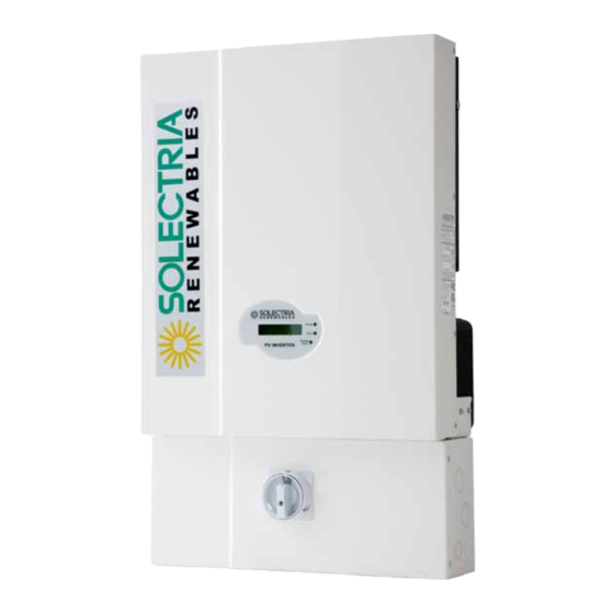
- Page 1 PVI 6500 PVI 7500 INSTALLATION AND OPERATION MANUAL Residential/Commercial Grid‐Tied Photovoltaic Inverter © 2012, Solectria Renewables, LLC All information subject to change without notice REV H 05/07/2012 ...
- Page 2 IMPORTANT SAFETY INSTRUCTIONS Before installing or using the PVI 6500‐7500, please read all instructions and caution markings in this manual and on the PVI 6500‐7500 unit as well as the PV modules. All electrical installations shall be performed in accordance with all local and national electrical codes. The PVI 6500‐7500 inverters are listed to UL1741/IEEE1547/CSA 22.2#107.1 (and comply with IEEE 62.41). The PVI 6500‐7500 inverters contain no user serviceable parts. Do not open the inverter. Please contact Solectria Renewables or a Solectria Renewables authorized system installer for maintenance. Connection of the PVI 6500‐7500 to the electric utility grid must be done after receiving prior approval from the utility company and performed only by qualified personnel. Completely cover the surface of all PV‐arrays with opaque material before wiring them or use other methods to prevent shock hazard. PV arrays produce electrical energy when exposed to sunlight and could create a hazardous condition. SAVE THESE INSTRUCTIONS ...
- Page 3 Insta allation and Operation M Manual (REV H) PVI 6500 0 / PVI 7500 This manual conta ains importan t instructions that shall be followed duri ing installatio n and mainte nance of the P PVI 6500 and PVI 7500 0 Inverter. To re educe the risk k of electrical shock, and to o ensure safe installation a nd operation of the inverte er, the follow wing safety sym mbols are u used to indica te dangerous conditions an nd important safety instruc ctions. ...
- Page 4 The normally grounded conductor may be ungrounded and energized when a ground fault is indicated. The AC Neutral connection is only for voltage sensing and shall be neither used to carry currents nor bonded to ground inside the inverter except in the case of 277VAC use, where the neutral is current‐ carrying. This list does not contain all measures pertinent to the safe operation of the device. If special problems arise which are not described in sufficient detail for the purposes of the user, contact your distributor, dealer or call the Solectria Renewables customer service hotline. SAVE THESE INSTRUCTIONS Safe Installation and Operation Installation of the device must be in accordance with the safety regulations and all other relevant national or local regulations. Correct grounding and over current protection must be provided to ...
- Page 5 Repair and Maintenance The inverter contains no user serviceable parts. Only Solectria Renewables personnel are authorized to carry out internal repair and maintenance of the unit. Please return the device for repair and maintenance. For maintenance and replacement of the fuses by qualified personnel, please refer to section 5.3. WARNING! Do not make alterations or tamper with components in the inverter without the manufacturer’s authorization ...
-
Page 6: Table Of Contents
Installation and Operation Manual (REV H) PVI 6500 / PVI 7500 Table of Contents Introduction ............................ 7 Installation ............................ 10 2.1 Checking for Shipping Damage ..................... 10 2.2 Inverter Mounting and Placement .................... 10 2.3 Electrical Connection and Connection to Electrical Utility Grid, Surge/Lightning Arrestors and Grounding Electrode Conductors ............ 18 2.4 Connection of AC Wiring ...................... 24 2.5 Connection of DC Wiring ...................... 27 2.6 Connection of Communication Wiring .................. 31 2.4 Communication ID adjustment ..................... 33 ... -
Page 7: Introduction
Installation and Operation Manual (REV H) PVI 6500 / PVI 7500 1 Introduction The PVI 6500 and PVI 7500 are single phase, grid‐tied PV inverters designed to be interconnected to the electric utility grid. By following the instructions in this manual, the PVI 6500 ‐ PVI 7500 can be installed and operated safely. This installation guide is to be used as reference for commissioning and as a guideline on how to use the inverter most effectively. Feeding power onto the grid involves conversion of the DC‐voltage from the PV‐array to grid compatible AC‐voltage by “inverting” DC to AC. This unit feeds power into a standard 240 VAC split phase electrical system or two phases of a 208 VAC, 3‐ phase commercial, industrial or institutional facility’s electrical system that is connected to the electric utility grid. The inverter can also be connected to one phase and neutral of a 277 VAC electrical service. If the PV system and inverter are providing the same amount of electrical power that the facility is using, no power is taken from or fed onto the utility grid. If the facility is using more power than the PV system is providing, then the utility grid provides the balance of power. If the facility is using less power than the PV system is generating, the excess is fed into the utility grid. Be sure to look into local regulations regarding net metering and interconnection in your local area. Note that some utilities need to change their revenue kWh meter to a bi‐directional type for proper net metering measurement or incentives/billing. Photovoltaic ... - Page 8 Data acquisition, display and communication The integrated data acquisition and communication capability of the PVI 6500‐7500 allows comprehensive tracking of system performance data. All error messages and operating conditions of the PVI 6500‐7500, as well as those on the PV system are shown on the display. An optional full‐featured, inverter direct data acquisition and logging gateway and web‐based service is available from Solectria Renewables, called SolrenView (http://www.solrenview.com). The gateway allows the inverter to deliver information to the Solrenview server through the facility’s internet service. Technical structure of the PVI 6500 and PVI 7500 A high frequency switching bridge circuit operating in conjunction with a high frequency transformer provides galvanic isolation of the photovoltaic system from the building’s AC power and electrical utility grid. The Maximum Power Point tracking algorithm continuously controls the PV voltage and current to produce the maximum possible power output during varying sunlight ...
- Page 9 Installation and Operation Manual (REV H) PVI 6500 / PVI 7500 Another important safety feature that has the ability to isolate the inverter from the grid is the DC ground fault detection and interrupt (GFDI) circuit. The PV array’s grounded conductor is bonded to ground inside the inverter through the GFDI fuse (and must not be bonded to ground at any other point outside of the inverter). PVI 6500‐7500 Description (inside) Fig. 1.2 PVI 6500/7500 Features Diagram (1) AC knockouts (2) PV array ground fault interrupt (GFDI) fuse (inside wiring box) (3) Combined DC/AC disconnect switch ...
-
Page 10: Installation
The PVI 6500/7500 inverters are thoroughly inspected and tested rigorously before they are shipped. Even though they are delivered in a rugged, heavy cardboard box with foam inserts, the inverters can be damaged in shipping. Please inspect the inverter thoroughly upon delivery. If any damage is discovered please notify the shipping company immediately. If there is any question about potential shipping damage, contact Solectria Renewables. A photo of the damage may be helpful. Solectria Renewables is not responsible for shipping damage. A claim must be filed with the shipping company. Solectria Renewables will assist you with this process as needed. ... - Page 11 Installation and Operation Manual (REV H) PVI 6500 / PVI 7500 that the inverter be mounted on the north or east side of buildings or on the northern side of a ground mounted PV array. Following these guidelines help prevent the unit from limiting the power produced due to an excessively high inverter temperature. In hot climates, the housing and heat sink can reach 160 F (70 C) and must be mounted on an appropriate material for this temperature as well as one that meets local codes. The inverter should not be mounted where people are likely to touch the case or heat sink due to the high potential temperature. CAUTION: Please follow these guidelines: The inverter weighs approximately 89 lbs (40.8kg) (shipping weight in the box with mounting plate is approximately 104 lb). Be sure to use a mounting method that will safely hold this weight. ...
- Page 12 Installation and Operation Manual (REV H) PVI 6500 / PVI 7500 Fig. 2.2.1 PVI 6500/7500 Dimensional Diagram Placement and location WARNING! Some parts of the heat sink can reach temperatures over 160F (70℃). Keep flammable, explosive materials or trash at an appropriate distance from the inverter! WARNING! Do not expose the inverter to corrosive liquids and/or gasses. ∙ The mounting bracket should be fastened to a concrete or a masonry wall using appropriate anchors. Conduit Locations, Pre‐punched Holes and Knock‐outs ∙ Multiple concentric Knock‐outs (KOs) are on the bottom, back and side of the AC and DC ends of the wiring box. ∙ Large Knock Outs are for 1”‐ ½” conduit. Small Knockouts are for ¾”‐½” conduit. ∙ Concentric KOs are on the back of the AC and DC sides of the wiring box for a “hidden wiring” installation. 12 ...
- Page 13 Installation and Operation Manual (REV H) PVI 6500 / PVI 7500 Fig 2.2.2 Clearances recommended for PVI 6500/7500 inverter installation Mounting details The steps listed below describe how to mount the inverter on the wall: ‐ After taking the inverter out of the cardboard box, you will find the bracket in the bag behind the heat sink. The bracket needs to be picked up from the inverter as shown in the figure 2.2.3 below. Fig 2.2.3 Unpacking the mounting bracket 13 ...
- Page 14 Installation and Operation Manual (REV H) PVI 6500 / PVI 7500 Fig 2.2.4 Remove the bracket from the inverter 1. Use the bracket (Fig 2.2.5) as a template to mark the hole locations on the wall. After drilling the holes, the mounting bracket should be fastened to the wall with screws or screw‐anchors as shown in Figure 2.2.6. 98.43 250mm 9.88” 180mm 7.12” 125mm 4.94” 2.91” 70mm 2.75” 2.75 4.75” 20.67” 7.5” 16.94” 14 ...
- Page 15 Installation and Operation Manual (REV H) PVI 6500 / PVI 7500 Fig 2.2.5 Mounting bracket and its dimensions 11.8” 23.6” 60cm 11.8” 58”‐ 67” 100~170cm ¼” diameter mounting screw recommended or 3/16‐1/4” anchor bolt Fig 2.2.6. Fastening the mounting bracket 2. Once the mounting bracket is fastened to the wall, the inverter and the wiring box can be hooked onto the bracket and slipped down into place. Make sure the lower lip on the bracket hooks into the window on the back of the inverter as shown in Fig. 2.2.7. 15 ...
- Page 16 Insta allation and Operation M Manual (REV H) PVI 6500 0 / PVI 7500 Flange with mounting hole Fig 2.2.7 M Mounting Inv verter on br r acket 16 ...
- Page 17 Installation and Operation Manual (REV H) PVI 6500 / PVI 7500 Fig 2.2.8 Fasten the inverter with screws at the bottom flange After the inverter is hooked properly on the bracket, secure it with screws at the bottom flange. 17 ...
-
Page 18: Electrical Connection And Connection To Electrical Utility Grid, Surge/Lightning Arrestors And Grounding Electrode Conductors
Installation and Operation Manual (REV H) PVI 6500 / PVI 7500 2.3 Electrical Connection and Connection to the Grid * Equipment grounds, grounding electrode conductor and ground fault detector/interrupter not shown PVI 6500‐7500 PV SYSTEM BLOCK DIAGRAM Fig. 2.3.1 Simplified electrical connection diagram * Colors used in wiring diagram are to differentiate conductors and are not representative of wire colors used pre code. ... - Page 19 AC Voltage: The PVI 6500‐7500 inverters are 240V AC grid connected devices. They are also suitable for 208V and 277V AC grid‐connected use. For example, connection between two phases of a 208V AC, 3‐phase service or connection between one phase and neutral of a 277V AC service (where acceptable by code). No unit (PVI 6500 or 7500) can be used with a 120V AC service. The units are factory pre‐set to auto‐detect 277VAC, 240VAC or 208VAC when connected with a neutral. They can also be configured for either 240 or 208 VAC without a neutral at the factory or by a qualified installer. Use with 277VAC must always use a neutral as the neutral is used as a current carrying conductor. WARNING: The inverter should not be opened at any time unless authorized by Solectria. The unit is sealed at the factory and its UL listing will no longer be valid and the warranty will be void if opened or tampered with in any way. Multiple Units: Multiple PVI 6500‐7500 units can be used at the same location as long as all electrical codes, local building codes and area utility guidelines are followed. If multiple units are used, each inverter must have its own dedicated AC over current protection device, and PV strings cannot be wired to multiple inverters. ...
- Page 20 Installation and Operation Manual (REV H) PVI 6500 / PVI 7500 AC Over Current Protection Device: A dedicated AC over current protection device is required for each PV inverter. Every PVI requires a 208V, 240V or 277V AC rated 2–pole over current protection device. The following is a table showing the appropriate over current protection device rating for the PVI 6500 and 7500 at different service voltages. AC Voltage PVI 6500 PVI 7500 208VAC 240VAC 277VAC AC and DC Disconnects: The integral AC & DC disconnects are standard features of the PVI 6500‐7500 inverters. The PV system may need additional AC or DC disconnect if required by the utility or local code. Connecting the AC Inverter Wiring: WARNING: The wiring of the PV inverter’s AC and DC connections must only be done with the building AC circuit breaker off and locked out and the PV array disconnected or covered with an opaque material (or other method that establishes electrically safe working conditions). Both AC and DC should be disconnected or turned off. The PVI 6500‐7500 inverters are not capable of feeding currents back into the PV array from the AC source including into short circuit(s) or fault(s) in the PV array or string(s). Connecting the Inverter Wiring: WARNING: Follow PV module manufacturer’s installation directions. PV arrays produce electrical energy when ...
- Page 21 Installation and Operation Manual (REV H) PVI 6500 / PVI 7500 Fig 2.3.3 Turn the DC/AC disconnect switch OFF Fig 2.3.4 Remove the 4 screws on the wiring box and remove the cover After the wiring box cover is removed, the conduit hole covers can be removed (or KOs in other locations punched out) as shown in the figure 2.3.5 for the DC and AC conduits which will enter and exit these locations. 21 ...
- Page 22 Installation and Operation Manual (REV H) PVI 6500 / PVI 7500 Fig 2.3.5 Punch out the knockouts where the conduits will enter the wiring box. The following three sections describe the wiring for the AC, DC, and communication ports. The AC and DC wiring shall be done in the wiring box of the PVI 6500/7500. AC Terminal Blocks PV String Fuse GFDI Fuse Fuse Bypass terminal Ground Bar DC Terminal Blocks RJ45-R RJ45-L Fig 2.3.6 Wiring box components and connections 22 ...
- Page 23 Installation and Operation Manual (REV H) PVI 6500 / PVI 7500 Two RJ‐45 connectors are used for external communication to a Solectria communication gateway. The AC terminal block is used to connect to the building/utility grid through a dedicated circuit breaker in the building distribution panel. WARNING! All electrical work shall be done in accordance with the local and national electrical codes and should follow the important safety instructions in this manual. WARNING! Local and national electrical codes state that the inverter must be connected to a dedicated circuit, and that no other outlets or devices can be connected to the same circuit. The code also imposes limitations on the size of the inverter and the manner in which it is connected to the utility gird. WARNING! Make sure that you use suitable conductors for both the AC and DC wiring. The conductors must be ...
-
Page 24: Connection Of Ac Wiring
Installation and Operation Manual (REV H) PVI 6500 / PVI 7500 With Neutral With Neutral 240/120 Split Phase 120 WYE Neutral Neutral 277V / 240V / 208V With Neutral Neutral With Neutral With Neutral 240 Delta 277 WYE 120 Stinger Without Neutral Without Neutral 240 Delta 208 Delta Fig 2.3.8 ... - Page 25 Insta allation and Operation M Manual (REV H) PVI 6500 0 / PVI 7500 RNING! Each h connection to a PVI 650 00‐7500 inve erter must be e installed w with a dedicat ted circuit br reaker with 3 30‐50 peres (depend ding on inver rter ...
- Page 26 Insta allation and Operation M Manual (REV H) PVI 6500 0 / PVI 7500 .2 Conne ection for AC 277V S Service/U Utility Volt tage ACIN_N1 DCIN- J119 J506 Connect the A AC black wire to terminal label ed "BLACK FOR 277V" of J506 N wire c connected to N L1 wire e connected to LI NE 1 terminal...
-
Page 27: Connection Of Dc Wiring
Insta allation and Operation M Manual (REV H) PVI 6500 0 / PVI 7500 5 Conne ection o of the D DC wiring g TION! PV a arrays are ene ergized when exposed to lig ght. Use safe working prac ctices when w working on PV V arrays. RNING! EXTR REME SHOCK A AND FIRE HAZ ZARD! MOVE ALL PV STRING FUSE ES BEFORE W IRING DC CO NNECTIONS! DO NOT REI INSTALL FUSE ES UNTIL YOU U ARE READY TO CO OMMISSION T THE INVERTER... - Page 28 Insta allation and Operation M Manual (REV H) PVI 6500 0 / PVI 7500 ACIN_N1 DCIN- DCIN+ J113 J119 Red DC wire Terminal label led “D” of disconnect switch Black DC wi Connect to PV+ Connect to PV- Termi inal labeled “C C”...
- Page 29 Insta allation and Operation M Manual (REV H) PVI 6500 0 / PVI 7500 DUCTOR (WIT THOUT STRIN NG FUSES)” of f J504 and the e negative po olarity of the DC input volt age from the e PV string sha all be conn nected to the terminal labe led “GROUND DED CONDUCT TOR” as show wn in the figure e 2.5.2.1. he negatively grounded set tting is that t the black DC w wire is conne ected to the t erminal label ed “C” of J50 05, and the re ed DC wire is connected to the termin nal labeled “D D” of disconne ct switch. ...
- Page 30 Installation and Operation Manual (REV H) PVI 6500 / PVI 7500 Fig 2.5.2.2 PV‐ String connections and AC connections 2.5.3 Wiring inverters in parallel PVI 6500‐7500 inverters can be connected in parallel when more power is needed. In the parallel configuration, each inverter shall connect to its own PV array. Do not connect one PV array to more than one inverter. This may cause the inverter to work abnormally. The Figure 2.5.3.1 on the following page shows the connections between inverters and PV arrays in parallel configuration. It is recommended balancing practice to alternate phase connections when connecting more than two inverters to the same three phase service. ...
-
Page 31: Connection Of Communication Wiring
Installation and Operation Manual (REV H) PVI 6500 / PVI 7500 Correct Configuration from DC Side Incorrect Configuration from DC Side Fig 2.5.3.1 Parallel configuration of inverters is done on the AC side not the DC side. 2.6 Connection of Communication wiring The PVI 6500‐7500 inverter supports two common data interface standards, RS‐232 and RS‐485 that will be used to communicate to a Solectria communication gateway. Only one of the communication interfaces can work at a time. As shown in the Figure 2.6.1, there are two RJ‐45 connectors, RJ45‐R and RJ45‐L that are located on the bottom of the wiring box. The pin numbers of the RJ‐45 connectors and the corresponding signals are described in the Figure 2.6.2 below. If the RS485 is used as the external communication interface and the inverter is the last device in the RS485 loop, then the termination switch shall be put to the ON position (shown in the figure 2.6.1). The installer needs to open the front cover of the wiring box to switch the termination switch into the ON position. The termination switch is set to the OFF position per default. 31 ... - Page 32 Installation and Operation Manual (REV H) PVI 6500 / PVI 7500 Spring terminal (J605) RS232 Termination Termination ON/OFF RJ45-L RJ45-R Fig 2.6.1 Positions of the communication ports and termination switches RJ45-L 1 TXD (RS232) 2 RXD (RS232) 3 Not used 4 GND 5 GND Top view 6 Not used 7 TX A (RS485) 8 RX B (RS485) RJ45-R 1 Factory reserved...
-
Page 33: Communication Id Adjustment
Installation and Operation Manual (REV H) PVI 6500 / PVI 7500 As shown in the Figure 2.6.2, the RS‐232 signal pins, TXD and RXD, are in the RJ45‐L connector. Therefore, only the RJ45‐L can be used to connect to when the RS‐232 interface is selected If RS‐485 interface is selected, both RJ‐45 connectors will be used for the daisy‐chained/cascaded RS‐485 connections shown in the Figure 2.6.3. Standard Cables available for RS232 & 485 communication for PVI 3000 through PVI 7500 Description Part Number Typical Use Length Cable, RS485 comm. PVI 3000‐7500 WIH‐020082 RS485 cable for communication gateways 7 ft Cable, RS485 daisy chain PVI 3000‐ WIH‐020081 RS485 jumper cable, for 3000‐7500 inverter‐to‐ 30 in. 7500 inverter ... - Page 34 Installation and Operation Manual (REV H) PVI 6500 / PVI 7500 Fig 2.7.1 DIP Switch for RS485 Communication Address Different ways to set communication ID ID Switch EEPROM setting Communication Condition (S201) (19) ID 1 1~254 (ignore) Use ID Switch setting 2 0 or 255 1~255 Use EEPROM setting 0 or >255 or 3 0 or 255 255 EEPROM error ID Switch value (S201) NO. of ID Switch ID Switch value bit 0 bit 1 bit 2 bit 3 bit 4 bit 5 bit 6 bit 7 Weighting OFF OFF OFF OFF OFF OFF OFF OFF ON OFF OFF OFF OFF OFF OFF OFF...
-
Page 35: Commissioning The Inverter And Pv System
Installation and Operation Manual (REV H) PVI 6500 / PVI 7500 3 Commissioning the Inverter and PV System Ensure that the inverter is mounted, all connections are made and you are ready to power it up before continuing with this section. NOTE: Make sure all tools, parts, etc. are removed from the vicinity of the inverter before turning it on. WARNING: Make a final check for correctness of all AC and DC wiring to the inverter and in the system. NOTE: With the PV modules connected and the inverter disconnect still in the off position, it is good practice to check PV polarity once more simply by carefully using a 600V, DC rated CAT III digital volt meter and probing the positive (+) and negative (‐) PV connections on the terminal blocks in the wiring box. Turning on the inverter for the first time: STOP! CHECK YOUR WIRING: WARNING! EXTREME SHOCK AND FIRE HAZARD! FAILURE TO FOLLOW THE FOLLOWING PROCEDURE CAN RESULT IN SERIOUS SHOCK, FIRE DAMAGE AND WILL VOID INVERTER WARRANTY! WARNING! ARC FLASH HAZARD! ALWAYS WEAR APPROPRIATE PERSONAL PROTECTIVE GEAR WHEN WORKING ON ENERGIZED CIRCUITS! o REMOVE WIRING BOX COVER, Watch for live terminals and fuse holders. o PV STRING FUSES SHOULD NOT BE INSTALLED AT THIS POINT (If they are installed, STOP! and see the section “Replacing PV Fuses” in the Maintenance section at the end of this manual) ... - Page 36 Installation and Operation Manual (REV H) PVI 6500 / PVI 7500 Watch for blinking green LED and LCD messages indicating a 5‐minute connect to grid countdown. Following this time, the inverter will come on‐line and begin to feed power into the AC circuit. Lastly, look for a steady green LED, indicating the inverter is now operating at the Maximum Power Point of the array. See LCD section (4) of manual for detailed description of messages and indications. Operation: The control electronics will be active as soon as DC (PV) voltage reaches 200VDC. The inverter will connect to the utility/building grid when the DC voltage first exceeds 260VDC (strike voltage). Next, the inverter will load the array, bringing the DC voltage down from 260VDC to no less than 230VDC. Once there is enough PV power at 230VDC to feed back AC power, the inverter will automatically start to do so. ...
-
Page 37: Power, Ground Fault, Error Led Indicators And Lcd Display
Installation and Operation Manual (REV H) PVI 6500 / PVI 7500 4 Power, Ground Fault, Error LED Indicators and LCD Display The inverter operates automatically without the need for user interaction or maintenance. The PVI 6500‐7500 automatically starts feeding AC power into the grid every morning as the sun rises, as soon as sufficient DC voltage and PV power is available. The inverter microcontroller runs through various checks before going online with the grid and feeding power into the grid. 4.1 Power, Ground Fault and Error LED Indicators There are three light‐emitting diodes (LEDs) mounted on the front of the inverter to show the operating condition of the inverter (to the right of the LCD display). Fig. 4.1.1 Power, Error, and Ground Fault Indicator LEDs and LCD Display The green LED "Power" shows the current operating condition. The yellow LED "Error" indicates whether there is an internal or external fault present and whether the AC grid back‐feed has been interrupted. The red LED "Ground Fault" shows if a ground fault is present. Description of LED symbols used to indicate LED status in this manual ○ LED ON ● LED OFF x Not relevant / Inconsequential ☼ LED ON 0.9 second/OFF 0.1 Second ¤ LED ON 0.1 second/OFF 0.9 Second ... - Page 38 Installation and Operation Manual (REV H) PVI 6500 / PVI 7500 LED Indication Table LED indicators Operating status Description Green Initialization The PVI 6500‐7500 is initializing. Yellow Red Green System Check mode The inverter is in System Check mode. Yellow Red Green Monitor mode The inverter is in Monitoring mode. Yellow Red Green Grid/MPP mode The inverter is feeding power back to the ...
-
Page 39: The Lcd Display
Installation and Operation Manual (REV H) PVI 6500 / PVI 7500 4.2 The LCD Display The PVI 6500‐7500 is supplied ready to operate. There are no user settings, which need to be made before power can be fed back into the grid. The device comes with a standard LCD display on which various data can be read. All LCD display values have accuracy tolerances of up to 5%. The PVI 6500‐7500 has a 16 x 2 LCD to show the operating status, input/output data, and system messages. As long as the DC input voltage is above the preset threshold value, the LCD continues to display the information following the process flow illustrated in the Figure 4.2.1. The process flow may follow the operating mode, fault mode, or idle mode. The operating mode is when the system goes from power‐on to system check, monitoring, and then grid feeding mode without any fault condition detected. If a fault condition that cannot be automatically be cleared is being detected during system check and monitoring mode, the system will ... - Page 40 Installation and Operation Manual (REV H) PVI 6500 / PVI 7500 G r i d T y p e 1 2 0 V 1 2 0 V 3 seconds ↓ If the grid type is set to 240 VAC without neutral, then the display will be looked as the figure shown below. G r i d T y p e L 1 - L 2 2 4 0 V 3 seconds ↓ ...
- Page 41 Installation and Operation Manual (REV H) PVI 6500 / PVI 7500 F a c H X X . X X H z C l r < X X X C y c s 3 seconds ↓ F a c L X X . X X H z C l r <...
- Page 42 Installation and Operation Manual (REV H) PVI 6500 / PVI 7500 Monitoring Mode Once system check is completed, the inverter goes into the monitoring mode. Even if all measurements needed for grid feeding are in the acceptable range, the system will keep monitoring these measurements for a period of time. The following information tells users that the system will go into the grid feeding mode in XXX seconds and then show the measured data of the DC input voltages and the existing voltage and frequency on the grid side. M o d e M o n i t o r i n N e x t C o n n e c t X X X s 3 seconds ↓ ...
- Page 43 Installation and Operation Manual (REV H) PVI 6500 / PVI 7500 M o d e G r i d / M P P 3 seconds ↓ The first two messages are about the PV array and output voltages and power. Vpv is the incoming DC voltage from the PV array. Wpv is the incoming power of the PV array in Watts. Vac, Pac, Iac, and Fac are the voltage, power, current, and frequency at the inverter output. ...
- Page 44 V a c H Warning Messages There are three possible warning messages that may be displayed to indicate failures. These messages can only occur in grid feeding mode. When EEPROM message is displayed, the system is unable to access the EEPROM. The COMM message means a failure of the communication function. The FAN BLOCK message shows that the fan has stopped running. These warnings could appear one after the other. Call the Solectria Renewables customer service hotline for resolution. W a r n i n g E E P R O M W a r n i n g C O M M W a r n i n g...
- Page 45 Installation and Operation Manual (REV H) PVI 6500 / PVI 7500 Fault Mode The fault mode messages are as follows. Fault mode, serial number of the inverter, software versions of the sequential and current controllers are shown and then the error messages which are listed in the Error Message Table in the Troubleshooting section 5, M o d e F a u l t S / N X X X X X X X X X X X X 3 seconds ↓ ...
- Page 46 Installation and Operation Manual (REV H) PVI 6500 / PVI 7500 T r i p X X X . X V P r e s e n t X X X . X V 3 seconds ↓ The message below shows the PV DC voltage is too high. M o d e F a u l t V p v H 3 seconds ↓ ...
- Page 47 Installation and Operation Manual (REV H) PVI 6500 / PVI 7500 SOLECTRIA PVI 7500 Fig 4.2.1 PVI 6500‐7500 inverter LCD display flow‐chart 47 ...
-
Page 48: Troubleshooting
The PVI 6500‐7500 is fitted with a self‐diagnostic system, which can recognize the majority of possible faults and show these on the display. This allows the operator to rapidly identify possible problems in the solar inverter or PV system. Please refer to the LCD section (4) for a thorough explanation of fault codes, modes, etc. Ground Fault: If a significant ground fault occurs in the PV array or wiring, the GFDI fuse (located in the wiring box) may be blown. If it is, locate and repair the ground fault and only then replace the fuse with Bussmann KLKD1 (1 Amp, 600VDC). Call the Solectria Renewables customer service hotline for assistance with locating a DC ground fault in the array or conduits. If the GFDI detects a ground fault, the Ground Fault LED will light and the “fault” will be displayed. Weak Sunlight Condition: Operation in weak sunlight, (for example early in the morning, when overcast or when snow is covering most or all of the PV array) can cause the inverter to go through a cycle of trying to start and restart several times. This can occur if the array reaches 260V (strike voltage) but there is nearly no power available. ... - Page 49 at a lower current ‐ If message occurs frequently contact the installing company InvTempMax The internal temperature of the inverter ‐ If the inverter is located in direct exceeded the safe operating limit. sunlight it may need to be shaded ‐ The VDC input may be too high causing increased temperature, reduce VDC input. ‐ Contact installing company or Solectria Renewables Relay Open Relay test failed. ‐ Contact installing company or Solectria Relay Close Renewables VacL1 H The voltage between L1 and neutral is over the ‐ Verify setting for S201 is correct for upper limit. the grid voltage applied ‐ Measure the AC voltage and compare to the voltage on the inverter display ‐ Contact Solectria Renewables for assistance if the range needs to be adjusted VacL1 L The voltage between L1 and neutral is under ‐ Verify setting for S201 is correct for ...
- Page 50 Installation and Operation Manual (REV H) PVI 6500 / PVI 7500 assistance if the range needs to be adjusted VacL2 L The voltage between L2 and neutral is under ‐ Verify setting for S201 is correct for the lower limit. the grid voltage applied ‐ Measure the AC voltage and compare to the voltage on the inverter display ‐ Contact Solectria Renewables for assistance if the range needs to be adjusted MOV Fault, AC High voltage protection function failed on the ‐ Verify MOV appearance is OK AC side. ‐ Contact Solectria Renewables MOV Fault, DC High voltage protection function failed on the ‐ Verify MOV appearance is OK DC side. ‐ Contact Solectria Renewables GFDI The GFDI Fuse is open or blown. ‐ Use DMM to verify GFDI is open contact installing company to inspect ...
-
Page 51: Maintenance
Installation and Operation Manual (REV H) PVI 6500 / PVI 7500 GFDI HW Error GFDI detect hardware failure ‐ Turn off the inverter and restart. ‐ If the error re‐occurs Contact installing company or Solectria Renewables IpvH Over current on the DC side ‐ Use a suitable meter for measuring the current from the array. ‐ Verify the current is within the limits for the inverter. ‐ Contact the installing company to check the array Driver Fault Driver circuit or power device failed ‐ Turn off the inverter and restart. ‐ If the error re‐occurs Contact installing company or Solectria Renewables CalDataError Calibration data is out of range ‐ Turn off the inverter and restart. ... - Page 52 Installation and Operation Manual (REV H) PVI 6500 / PVI 7500 WARNING! For continued protection against risk of fire, replace only with the same type and ratings of fuse (600 VDC, 1A)! Replacing the PV String Fuses The inverter is shipped with five (5) 15A, 600Vdc PV string fuses for PV strings. However, the size of the PV string fuse is determined by the electrical ratings of the PV module and by UL and code requirements. The minimum size of the PV string fuse is calculated using the short circuit current rating (Isc) of the PV module. Please be sure to consult with the PV module manufacturer for appropriate PV string fuse rating. IN NO CASE SHALL FUSES OF LARGER THAN 20A BE USED IN THE PV STRING ...
-
Page 53: Factory Service
PV arrays are always energized when exposed to light therefore hazardous voltage is still present on the terminal blocks and the PV string fuse holders even when the DC/AC disconnect switch is switched OFF. Please cover the PV arrays with opaque materials during PV string fuse replacement. CAUTION! The string fuse size must not be greater than the maximum fuse size rating of the PV module provided on the PV module manufacturer data sheet. If no maximum fuse size is indicated, please contact the PV module manufacturer. 5.4 Factory Service Please contact Solectria Renewables customer service hotline for our documentation on removing and replacing the top inverter section (while leaving wiring box in place). 5.5 Inverter Replacement Once the product is diagnosed and Solectria determines that it requires Factory Service, the product can be removed and sent back using the original shipping box and packing materials. A copy of the RMA number must be included in the package. Documentation: There is some documentation that must be provided with the returned product. Please include as much detail as possible. 1. Serial number and part number of the inverter ... - Page 54 Installation and Operation Manual (REV H) PVI 6500 / PVI 7500 Fig 5.5.1.1 Remove the cover of the Inverter J504 DC wires Disconnect J506 AC wires switch Fig 5.5.1.2 Remove the DC and AC wires 54 ...
- Page 55 Installation and Operation Manual (REV H) PVI 6500 / PVI 7500 Fig 5.5.1.3 Remove the nuts attaching the inverter and wiring box Fig 5.5.1.4 Remove the attachment screws on the sides of the inverter Fig 5.5.1.5 Remove the inverter carefully from the hangers on mounting bracket 55 ...
- Page 56 Installation and Operation Manual (REV H) PVI 6500 / PVI 7500 Back View Fig 5.5.1.6 Position the cover plate and fasten the screws 56 ...
- Page 57 Installation and Operation Manual (REV H) PVI 6500 / PVI 7500 Fig 5.5.1.7 Position the cover plate and fasten the screws 1. Turn the DC/AC disconnect switch to OFF position and turn off and lock out all breakers. 2. Wait for at least 5 minutes. 3. Remove the cover of the wiring box by following the steps described in section 2.3, as shown in the figure 5.5.1.1. 4. Disconnect the red and black DC wires from the disconnect switch and J505 terminal. Disconnect the red, black and white AC wires from the disconnect switch and J506 terminal as shown in figure 5.5.1.2. 5. All disconnected wires must be wrapped with insulating materials to prevent electric shock. Place the disconnected wires inside the wiring box. 6. Loosen the 4 nuts with a 13‐mm wrench as shown in the figure 5.5.1.3. 7. Remove the screws bonding the sides of the inverter so that the inverter can be taken apart from the wiring box as shown in the figure 5.5.1.4. 8. Remove the inverter from the mounting bracket as shown in the figure 5.5.1.5. 9. Use the cover plate that is on top of the wiring box to cover the through holes of the wires with the 4 nuts as show in the figure 5.5.1.6. 10. Put the front cover of the wiring box back and fasten the screws as shown in the figure 5.5.1.7. 11. Collect the removed screws in a plastic bag and place aside for reinstalling the inverter in the future. 12. Keep the DC/AC disconnect switch and circuit breakers locked in the OFF position until the inverter is reinstalled, all wires are connected correctly, front covers are replaced and screws are fastened. 5.5.2 Reinstall the Inverter After reinstallation of the inverter, all wires must be reconnected correctly before the inverter can be returned to service. WARNING! ...
- Page 58 Installation and Operation Manual (REV H) PVI 6500 / PVI 7500 Back View Fig 5.5.2.1 Re‐install the cover plate and attach it at the back of the wiring box 58 ...
- Page 59 Installation and Operation Manual (REV H) PVI 6500 / PVI 7500 Fig 5.5.2.2 Hang the inverter on the mounting bracket carefully Fig 5.5.2.3 Fasten the screws at the sides of the inverter 59 ...
- Page 60 Installation and Operation Manual (REV H) PVI 6500 / PVI 7500 Fig 5.5.2.4 Fasten the nuts that attach the inverter and wiring box Fig 5.5.2.5 Connect the AC and DC wiring to their correct terminals 60 ...
- Page 61 Installation and Operation Manual (REV H) PVI 6500 / PVI 7500 Fig 5.5.2.6 Put the wiring box cover back on Fig 5.5.2.7 Fasten the cover screws then 1. Verify that DC/AC disconnect switches and breakers are turned off and locked out. Verify the absence of voltage with a voltmeter. 2. Remove the front cover of the wiring box by following the steps described in section 2.3. 3. Remove the cover plate used to cover the through holes of the wires and put it back to its original place as shown in the figure 5.5.2.1. ...
-
Page 62: Product Warranty & Rma Policy
For three-phase inverters 10kW and higher: Solectria Renewables covers parts, travel and labor necessary to repair the product and shipment of parts to and from the customer via a Solectria Renewables-selected non-expedited surface freight within the contiguous United States, Canada and Mexico. For Alaska, Hawaii and all other installation locations Solectria Renewables will supply necessary parts as needed for warranty repairs;... - Page 63 What does the Solectria Renewables warranty not cover? Solectria Renewables Limited Warranties do not cover normal wear and tear of the product or costs related to the removal, installation, or troubleshooting of the customer's electrical systems. These warranties do not apply to and Solectria Renewables...
- Page 64 INTEGRATION OR OPERATION OF THE PRODUCT, REGARDLESS OF WHETHER SUCH INSTALLATION, INTEGRATION OR OPERATION WAS PERFORMED PROPERLY OR IMPROPERLY. Solectria Renewables neither assumes nor authorizes any other person to assume for it any other liability in connection with the repair or replacement of the Product.
-
Page 65: Return Material Authorization Policy
WARNING: LIMITATIONS ON USE Please refer to your product user manual for limitations on uses of the product. Specifically, please note that Solectria Renewables products are not intended for use in connection with life support systems and Solectria Renewables makes no warranty or representation in connection with any use of the product for such purposes. -
Page 66: Technical Data
20 deg C at -20 deg C Voltage (VDC) Fig. 7.1.1 Example representative ~100W PV module voltage – current characteristic at various cell temperatures Because PV modules also have a reduction in voltage at high cell temperatures, you must make sure the MPP voltage of the strings will not drop below the minimum inverter DC input voltage of 230V DC in very hot temperature conditions, including wire losses and voltage drop in order to avoid reduced system performance. Both the maximum open circuit voltage (OCV) when at cold extreme and minimum MPP voltage when at hot extreme can be calculated for a PV module using its specification sheet. Solectria Renewables’ online PV module string sizing tool can then be used to determine how many modules can be used in a string. 66 ... - Page 67 Installation and Operation Manual (REV H) PVI 6500 / PVI 7500 Inverter Specifications Name‐Part number PVI 6500 PVI 7500 Grid output (AC) Grid voltage, nominal (VAC) 208 240 277 VAC 244~304@277 VAC Grid voltage, operating range (VAC) 212~264@240 VAC 184~228@208 VAC Grid frequency, nominal 60 Hz Grid frequency, operating range 59.3~60.5 Hz Maximum output power 6500W 7500W 23.5A@277 VAC 27.1A@277 VAC Maximum output current 27.1A@240 VAC 31.3A@240 VAC 31.3A@208 VAC 36.1A@208 VAC 30A@277 VAC 35A@277 VAC Output over current protection 35A@240 VAC 40A@240 VAC 40A@208 VAC 50A@208 VAC Maximum output fault current ...
- Page 68 Installation and Operation Manual (REV H) PVI 6500 / PVI 7500 Noise level at full load < 47db(A) at 1m Mechanical Outdoor enclosure NEMA 3R, Rainproof Cooling Cooling fan DC Input terminals Accepts wire size of #10 to #6 AWG AC Output terminals Accepts wire size of #10 to #6 AWG DC conduit connection access 1” knockout (1.38") / ¾” knockout (1.06") AC conduit connection access 1” knockout (1.38") / ¾” knockout (1.06") Communication connection ¾” knockout (1.06") / ½” knockout (0.79") Mechanical Weight / Shipping weight 41 kg / 47 kg (90 lb / 104 lb) Dimensions (HxWxD) 28.8 x 17.2 x 8.2" (732 x 438 x 208 mm) Shipping dimensions (HxWxD) 33.1 x 21.65 x 13.98" (840 x 550 x 355 mm) Communication Interface Communication RS232 and RS485 Communication protocol MODBUS LCD display Yes LED indicators Red / Green / Yellow Positive ground inverters Name‐Part number ...
- Page 69 Installation and Operation Manual (REV H) PVI 6500 / PVI 7500 Measurement precision Resolution Range Accuracy Display Measurement Input voltage (VDC) 0~640V 0.1V 0.6V ±2V Input Current (IDC) 0~31000mA 100mA 31mA ±300mA Grid voltage (VAC) 0~300V 0.1V 0.6V ±1V Grid current (IAC) 0~26000mA 100mA 52mA ±250mA Grid frequency (Hz) 45~65Hz 0.1Hz 0.004Hz ±0.02Hz Output power (W) 0~7800W ...
- Page 70 Installation and Operation Manual (REV H) PVI 6500 / PVI 7500 Fig 7.1.4 Temperature de‐rating curve of the PVI 7500 (240VAC) at 3 DC voltages Fig. 7.1.5 Serial Number Key (description) PVI 3000 ‐ 7500 70 ...
-
Page 71: Appendices
Appendices Appendix A: PVI 6500/7500 brochure The brochure can also be viewed on the website: http://www.solren.com/pvi3000‐7500.html The PDF version datasheet link is: http://www.solren.com/downloads/PVI6500‐7500Manual.pdf Appendix B: Example string sizing PVI 6500/7500 String sizing tool, “PV System Builder” specific link at: http://www.solren.com/stringSizing.html Appendix C: Contact Information Authorized Distributors Specific link: http://www.solren.com/distributors.html Solectria Renewables LLC 360 Merrimack Street Building 9 Lawrence, Massachusetts, 01843 USA Tel: 978.683‐9700 Fax: 978.683‐9702 Email: inverters@solren.com Website: www.solren.com Appendix D – Positively Grounded Option Ref: Connection of the DC wiring See section 2.5 Connection of the DC wiring in the Wiring section for standard wiring for negatively grounded systems and refer to it while connecting for positively grounded systems using this appendix including use of all the warnings and cautions. CAUTION! For positively grounded systems, polarities of each DC input from a PV string shall be correctly connected to the “Grounded Conductor” (positive) and “Ungrounded Conductor” (negative) terminals respectively. The DC ... - Page 72 Insta allation and Operation M Manual (REV H) PVI 6500 0 / PVI 7500 The PVI 6500‐750 0 inverter sup pports positive ely grounded arrays. To con nfigure the in verter for pos sitive grounde ed arrays, the integ grated discon nect must bre eak the ungro unded, negat ive conductor r. Ensure that t he inverter is off and de‐en nergized from both AC and DC sides. Disconnect th he black DC w wire connected d to terminal “ “C” on termin nal block. ...
- Page 73 Insta allation and Operation M Manual (REV H) PVI 6500 0 / PVI 7500 The “+” c cable of the D DC input voltag ge shall be co nnected to th he terminal lab beled “GROUN NDED CONDU UCTOR” and th he “‐” wire of th he DC input vo oltage shall be e connected t to the termina al labeled “UN NGROUNDED CONDUCTOR” ”. Avoid usi ing wire nuts to join any w wires together or to make a ny connection ns anywhere in the PV syst tem. Wire nut ts are a frequen nt cause of un nreliable and r resistive conn...
-
Page 74: Appendix E: Fault Repot Form
Installation and Operation Manual (REV H) PVI 6500 / PVI 7500 PVI 6500‐7500 PV Inverter Fault Report Form Appendix E. Basic information Model (i.e. “PVI 7500”) Serial number Purchased from Purchased date Y/ M/ D Installation information Residential Commercial Type of installation Installation date Y/ M/ D First operation date Y/ M/ D AC wire size and length ____ AWG wire size feet length of wire DC wire size and length ____ AWG wire size feet length of wire Roof Pole ... -
Page 75: Appendix F: Ul1741/Ieee1547 Listing Letter
Installation and Operation Manual (REV H) PVI 6500 / PVI 7500 Appendix F – UL1741/IEEE1547 and CSA22.2#107.1 Listing Letter 75 ...
Need help?
Do you have a question about the PVI 6500 and is the answer not in the manual?
Questions and answers