Table of Contents
Advertisement
Advertisement
Table of Contents

Related Manuals for Solectria Renewables PVI 3800TL


Summary of Contents for Solectria Renewables PVI 3800TL
- Page 1 Installation and Operation manual for PVI 3800TL PVI 5200TL PVI 6600TL PVI 7600TL...
- Page 2 This manual accompanies our equipment for use by the end users. The technical instructions and illustrations contained in this manual are to be treated as confidential and no part may be reproduced without the prior written permission of SOLECTRIA RENEWABLES, LLC. Service engineers and end users may not divulge the information contained herein or use this manual for purposes other than those strictly connected with correct use of the equipment.
-
Page 3: Table Of Contents
Table of Contents General safety instructions Safety symbols and terminology definitions Safety Instructions Introduction System Data evaluation and communication Technical structure of the inverter Ambient temperature Inverter DC input voltage range Efficiency Equipment overview Inverter Nameplate and Safety Labels Installation Visual inspection Installation location Mounting the inverter... - Page 4 Commissioning the PV system Status LEDs Display and keypad 5.2.1 Components 5.2.2 Display layout 5.2.3 Keys 5.2.4 General menu structure Inverter turn-on procedure Inverter turn-off procedure Standard initial commissioning 5.5.1 Brief overview of the commissioning steps 5.5.2 Detailed description of the commissioning steps Setting values Production Information Overview...
- Page 5 Event log 8.2.1 Overview 8.2.2 External events menu 8.2.3 Change events menu Trouble-shooting and correction 8.3.1 External events / Insulation and grounding failures 8.3.2 Internal failures 8.3.3 Other LED and display messages Displaying grid settings Internal log Maintenance Repair Removal, transport, storage, disposal 10.1 Removal 10.2...
- Page 6 String fuse replacement procedure Conduit installation and AC wiring routing PVI 3800TL - AC voltage loss in different wire sizes and lengths PVI 5200TL/PVI 6600TL/PVI 7600TL - AC voltage loss with different wire sizes and lengths Wiring box AC assembly - terminal labeling...
-
Page 7: General Safety Instructions
Solectria inverters to reduce the risk of personal injury and to ensure a safe installation. Installation, commissioning, service, and maintenance of Solectria models PVI 3800TL, PVI 5200TL, PVI 6600TL and PVI 7600TL inverters must only be performed by qualified personnel that are licensed and/or satisfy state and local jurisdiction regulations. -
Page 8: Safety Instructions
The inverter section contains no user-serviceable parts. For all service and maintenance, the inverter should be returned to a Solectria Authorized Service Center. • Read all of these instructions, cautions, and warnings for the Solectria inverter and associ- ated PV array documentation. •... -
Page 9: Introduction
Introduction With this device you have acquired a inverter for connection of a photovoltaic system to the grid. This inverter is characterized by an advanced housing design and state-of-the-art high-frequency technology, which enable the highest levels of efficiency and longest life. The inverter includes key features and capabilities, such as anti-islanding protection, LCD, RS485 interfaces. -
Page 10: Data Evaluation And Communication
Data evaluation and communication The integrated data display, processing and communication of the device enables easy operation of the inverter. Monitoring of the operational status and signaling of operational failures are capable of being reviewed on the device display. The data interfaces enable the downloading of data. The best way of accessing this functionality is via a monitoring system, such as SolrenView, con- nected to your inverter. -
Page 11: Ambient Temperature
100% Nom. output pwr @ 380 V @ 500 V @ 200 V Figure 1: Solectria PVI 3800-7600TL inverter output power vs ambient temperature curve* Inverter DC input voltage range Figure 2: Solectria PVI 3800TL DC input voltage range... -
Page 12: Efficiency
Figure 3: PVI 5200TL and PVI 7600TL PV input DC voltage range 2.6 Efficiency The best efficiency of the inverter is obtained at input voltages > 320V for 208V grid, and input voltages > 380V for 240V grid. Figure 4: PVI 3800TL efficiency plot... -
Page 13: Equipment Overview
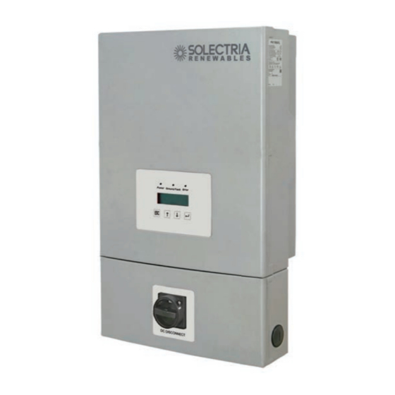
Figure 5: PVI 7600TL efficiency plot Equipment overview (1) Inverter Power Stage (2) LED Indicators (3) LCD (4) Keypad (5) Mounting Bracket (6) Lockable DC Disconnect Figure 6: Exterior view of inverter main (7) Wiring Box Cover components (8) Wiring Box (9) Conduit Plugs... -
Page 14: Lockable Dc Disconnect
A further description of the equipment features: (1) Inverter Power Stage - This is the inverter section of the assembly. This section is sealed at the factory and there are no user-serviceable parts inside. All wiring to install the inverter is done in the wiring compartment. -
Page 15: Inverter Nameplate And Safety Labels
Inverter Nameplate and Safety Labels Figure 8: Nameplate Label location The nameplate label is shown in figure 8. The inverter serial number can be found on the nameplate label. *Models PVI-5200TL, PVI-6600TL & PVI-7600TL are not UL Listed by UL LLC as of the time of print of this manual.“... -
Page 16: Location Of Caution Labels
The main caution label in English is on the left side of the inverter in the middle of the unit and the equivalent label in French is located just above as shown in the illustration. WARNING: MORE THAN ONE LIVE CIRCUIT. -
Page 17: Dimensions Of Pvi 3800Tl Inverter
Figure 10: Dimensions of PVI 3800TL inverters Figure 11: Dimensions of PVI 5200TL, PVI 6600TL and PVI 7600TL inverters... -
Page 18: Wiring Box Connection Options
(1) Fuse Holders (6) AC side Neutral (2) RS485 Termination (7) AC side L2 (3) PV Positive Terminals (8) AC side L1 (4) PV Negative Terminals (9) RS485 communication ports (5) AC side Grounding Terminals Figure 12: Wiring box connection options Required torques for wiring box terminals Terminals in figure 12 Wire size permitted... -
Page 19: Installation
Installation Read all of these instructions, cautions, and warnings for the Solec- WARNING! tria PVI inverter and associated PV array documentation. AVERTISSEMENT! Installation and commissioning must be performed by a licensed WARNING! electrician in accordance with local, state, and National Electrical AVERTISSEMENT! Code ANSI/NFPA 70 requirements. -
Page 20: Visual Inspection
Mounting bracket c. Operation and Installation Manual Visually inspect the Solectria PVI inverter for any physical damage such as a bent heatsink fin and dented chassis. If the inverter appears to be damaged or if the inverter needs to be returned, please contact your local Solectria representative. -
Page 21: Mounting The Inverter
Mounting the inverter Please make sure the inverter is installed vertically, especially if it is installed outdoors. Inverter should be at least >20" 20“ (50.8 cm) from any (50.8 cm) ceiling surface >4" >6" >6" (10 cm) (15.2 cm) (15.2 cm) (15.2 cm) (15.2 cm) Inverter should be mounted... -
Page 22: Installing The Mounting Bracket And Inverter On A Wood Stud Wall
5.91in (150mm) 4.72in (120mm) 9.45in (240mm) Figure 14: Dimensional drawing of mounting plate Mount the mounting plate to the wall with at least 4 screws and anchors (Ø 1/4“). With 4 screws use 4 holes A or 4 holes B (see Figure 14). You can use the mounting plate as a template for marking the positions of the boreholes. -
Page 23: Required Torques For Pvi Inverters
As the inverters are heavy, they should be lifted out of the cardboard container by at least two persons (PVI 3800TL weighs 42 lbs (19 kg) and PVI 5200/6600/7600TL weigh 64 lbs (29 kg)). -
Page 24: Electrical Connections
Electrical connections General safety Read all of the instructions, cautions, and warnings for the Solectria WARNING! PVI inverter and associated PV array documentation. AVERTISSEMENT! Installation and commissioning must be performed by a licensed WARNING! electrician in accordance with local, state, and National Electrical AVERTISSEMENT! Code ANSI/NFPA 70 requirements. -
Page 25: Utility Ac Voltage
Utility AC voltage The Solectria PVI inverters are grid-tied to the public utility. PVI inverters are software configurable via the user display panel for various 208 Vac or 240 Vac 60 Hz service configurations as shown in figures 18-22. The Solectria PVI Inverters should never be connected to a CAUTION! 120 Vac utility service. -
Page 26: V Delta Ac Grid
Figure 19: 240V Delta AC Grid Figure 18: 208V/120V WYE AC Grid Figure 20: 240V/120V Stinger AC Grid Grid Configurations NOT Allowed: Figure 21: 480V Delta AC Grid Figure 22: 480V/277V WYE AC Grid... -
Page 27: Ac Circuit Breaker Requirements
There are a large number of PV module string combinations that will offer optimal performance from either the PVI 3800TL, PVI 5200TL, PVI 6600TL and PVI 7600TL inverters due to its wide MPP DC voltage range (200 V – 500 V). -
Page 28: Inverter Connections
Follow the temperature multiplication factors given in NEC 690.7 table and the PV module manufacturer specified V/Temp coeffici- INFORMATION! ent to ensure PV string voltage is less than < 600 Vdc. Maximum INFORMATIONS! inverter PV input voltage for all possible weather conditions in the location of installation. -
Page 29: Pvi 3800Tl Inverter Electrical Diagram
Figure 23: PVI 3800TL Inverter electrical diagram Figure 24: PVI 5200TL, PVI 6600TL and PVI 7600TL Inverter electrical diagram... -
Page 30: Opening The Wiring Box Cover
POWER FED FROM MORE THAN ONE SOURCE, MORE THAN WARNING! ONE LIVE CIRCUIT. Please note that there are three DC inputs AVERTISSEMENT! that may all carry current. Please see diagram above. 4.8.2 Opening the wiring box cover Ensure no live voltages are present on PV input and AC output WARNING! circuits, and verify that the DC disconnect, AC disconnect, and de- dicated AC branch circuit breaker are in the “OFF”... -
Page 31: Wiring Box Conduit Openings
4.8.3 Wiring box conduit openings Conduit openings are provided for 1 inch and ½ inch conduit fittings. If conduit fitting used is bet- ween 1 inch and ½ inch (2.54 cm and 1.27 cm), an appropriate conduit reducer should be used. 1 in. -
Page 32: Pv Array String Input Connections
0.5 inch 6 inches Figure 28: Conduit installation and wiring routing Conduit fittings need to be water tight with either a NEMA 4, 4X, 6, or 6X rating insulated type is preferred. Once conduit and fittings are installed, route wiring thru conduit and fitting and allow a 6 inch strain relief service loop within the wiring box compartment. -
Page 33: Wiring Box - Pv Input Connections
The PV Array positive or negative leads must not be connected to INFORMATION! ground before the inverter! INFORMATIONS! All screw terminals accept solid or stranded copper 14 – 6 AWG wire only. A 3.5 mm flat blade screw driver is recommended for INFORMATION! tightening screw terminals to a 10.5 in-lbs. -
Page 34: Selecting Pv String Fuse(S)
PV string fuse information and calculating string fuse size The PVI 3800TL, PVI 5200TL, PVI 6600TL, and PVI 7600TL inverters are shipped with 3 X 15 A 600Vdc Littlefuse KLKD 15 string fuses. The provided string fuses may or may not be appropriate for your particular installation. -
Page 35: String Fuse Replacement Procedure
It is worth noting that for this example we calculated the minimum series fuse rating. However, it may be appropriate to use the supplied 15 A fuses insofar as they do not exceed the maximum se- ries fuse rating (provided by the module manufacturer) or the overcurrent protection requirements of your PV source wires. -
Page 36: Inverter Ac Output Wire Connections
Inverter AC output wire connections – Read all of the instructions, cautions, and warnings for the WARNING! Solectria PVI Inverter and associated PV array documentati AVERTISSEMENT! – Installation and commissioning must be performed by a licensed electrician in accordance with local, state, and National Electrical Code ANSI/NFPA 70 requirements. -
Page 37: Conduit Installation And Ac Wiring Routing
Pages 37-38 contain diagrams for each PVI inverter model to help determine the best wire size for your particular installation. Solectria recommends you select a wire size and length to ensure a maximum voltage loss between 1 - 2 %. Please note that the diagrams only offer ap- proximate voltage loss and more precise voltage loss should be calculated by a licensed electri- cian in accordance with local, state, and National Electrical Code ANSI/NFPA 70 requirements. - Page 38 0.4% 0.0% One way distance in feet Figure 33: PVI 3800TL-AC voltage loss with different wire sizes and lengths PVI 7600TL Percentage of voltage loss with 208 V AC and 240 V AC service. The load used in the calculation is the max.
-
Page 39: Wiring Box Ac Assembly - Terminal Labeling
AC-side Terminals PE Terminal (Grid Ground) L1 Terminal N Terminal GET (Grounding Electrode Terminal) L2 Terminal Figure 35: Wiring box AC assembly – terminal labeling Stranded copper wire should be checked so that all strands go into NOTICE! the terminal opening. AVIS! AC disconnect may be required by your local AHJ. -
Page 40: Inverter Rs485 Communication Connections
AVERTISSEMENT! Interface connection RS485 The Solectria PVI inverters offer an RS485 communication interface which can address up to 16 daisy chained inverters. For optimal performance, all unused interface connections must always be terminated by placing the termination jumper in the “on” position. -
Page 41: Commissioning The Pv System
Programmable, 2400/4800/9600/19200/38400, default = 19200 Data Bit Stop Bit Parity Contact Solectria for available 485 cables for daisy-chaining 485 on multimple inverters or con- necting to SolrenView monitoring logger. Commissioning the PV system Read all of these instructions, cautions, and warnings for the WARNING! Solectria PVI inverter and associated PV array documentation. -
Page 42: Status Leds
Verify that the dedicated 2-pole 240 Vac / 208 Vac circuit breaker WARNING! in the building electrical service panel is turned-off. AVERTISSEMENT! With the disconnect in the “OFF” position, verify the PV input NOTICE! polarity once more simply by carefully using a 600 V, DC rated digital volt meter and probing the positive (+) and negative (-) PV AVIS! array connections. -
Page 43: Keys
5.2.3 Keypad Symbol • Exit the current menu • Cancel the setting of a value • Move upwards in a menu • Set a value (increase the value) • Move downwards in a menu • Set a value (decrease the value) •... -
Page 44: Inverter Turn-Off Procedure
Inverter turn-off procedure 1. Turn off the AC disconnect (put in open position). 2. Turn off the dedicated 2-pole 240 Vac / 208 Vac circuit breaker in the building electrical service panel (put in open position). 3. Turn off the DC disconnect (put in open position). Standard initial commissioning 5.5.1 Brief overview of the commissioning steps... - Page 45 Select Continue and press the key. - - - - - - - - - - - - - - - - - - - G r i d S e l e c t i o n G r i d : U S 2 0 8 D C o n t i n u e - - - - - - - - - - - - - - - - - - -...
-
Page 46: Setting Values
Setting values You can set parameters in several menus. The keys are used to change parameter values. key increases the value of the parameter. key decreases the value of the parameter. key can be used to cancel the setting, and the original value is then displayed once more. Pressing the key causes the new parameter value to be adopted. - Page 47 Keys Action Result 1 1 0 D a t e a n d t i m e 6. Use the keys to set the month. F o r m a t D a t e : 1 8 / 7/ 2 0 1 3 T i m e : 1 3 : 1 0 : 2 0 p m 1 1 0 D a t e a n d t i m e...
-
Page 48: Production Information
Production Information All production information is provided for orientation purposes NOTICE! only. The measuring devices and meters provided by the electrici- ty supply company are the authoritative source of information AVIS! for invoicing. Overview The 400 Production info menu contains current data and statistics. The information is write-protec- ted and cannot be edited. -
Page 49: Current Data
Current Data Relevant menu The actual production data is provided in the menu 410 Current data. Access – Access the menu by navigating to Main menu > Production info > Current data. → The 410 Current data menu is displayed. 4 1 0 C u r r e n t d a t a - - - - - - - - - - - - - - - - - - - C u r r e n t o v e r v i e w... -
Page 50: Other Statistics
Sub-menu Contents and example display 41A Date and time Shows the current date and time. Use the 110 Date and time menu to set the values, see “7.2.1 Date and time”. 4 1 A D a t e a n d t i m e D a t e : 1 8 / 0 6 / 2 0 1 3 T i m e :... - Page 51 4 9 0 H i s t o r y D a y : 1 0 . 1 0 . 1 2 D a y : 1 0 . 1 0 . 1 2 D a y : 1 0 . 1 0 . 1 2 Structure Sub-menu Contents...
-
Page 52: Deleting Statistics
Sub-menu Contents 423 Day stat. ISO Statistics for: maximum/minimum insulation resistances 433 Week stat. ISO 443 Month stat. ISO 453 Year stat. ISO 463 Total stat. ISO Pmax Maximum power Imax Maximum current 4 2 3 D a y s t a t . I S O R I S O m a x : - - - - k Ω... -
Page 53: Settings
Select the option Yes and press the key to delete the statistic. R e s e t d a y s t a t . - - - - - - - - - - - - - - - - - - - Y e s →... -
Page 54: Date And Time
7.2.1 Date and time Description Menu 110 Date and time Menu access Main menu > Install settings > Date and time Example display 1 1 0 D a t e a n d t i m e F o r m a t D a t e : 1 8 / 0 6 / 2 0 1 3 T i m e :... -
Page 55: Contrast
NOTICE! You require a new PIN each time you wish to select a new grid. You obtain a PIN from the Solectria Support Team on request. AVIS! You must provide a key in order to receive a PIN. You will find the key in the menu 132 Grid change. -
Page 56: Rs485
The key consists of 11 numbers and letters. The Solectria Support Team will provide you with the four digit PIN. When you have received the PIN, navigate to the menu 132 Grid change and press the key. → The first digit of the PIN flashes. -
Page 57: Grid Feed-In Settings
Configurable parameters Display text Designation Description RS485 ID 1...255 2400 | 4800 | 9600 | 19200 | 38400, the standard Baud rate Baud rate is 19200 Connecting multiple inverters via RS485. NOTICE! ► Select a different ID for each inverter. AVIS! ►... -
Page 58: Shading
7.4.1 Shading Description The “Shading“ option is an extended MPP tracker. When the option is switched on, the MPP tracker performs an additional search at regular intervals. The MPP tracker then searches for the maximum power over a wider voltage range. This option should be switched on if shadows regularly pass slowly over the PV modules in the course of a day. -
Page 59: Standard Menu
Standard menu Description A standard menu can be defined, which is automatically displayed when the display keys are not used for a certain period of time. When the standard menu is displayed, pressing the displays the main menu. The standard menu is set to 411 Current data at the factory. This menu shows the current data and current operating messages. -
Page 60: Diagnosis And Maintenance
Diagnosis and maintenance Operating states 8.1.1 Types of operating states Associated influencing Operating state Grid feed-in factors No factors are present that Normal operation influence the production results. Non-critical factors that can affect the production results Limited operation Different but which are not failures (e.g., self-test). -
Page 61: Display Of The Actual Operating State
Insulation and grounding failures Insulation and grounding failures are logged and displayed when this failure occurs. 8.1.3 Display of the current operating state The actual operating state is indicated via LEDs. A short message is also shown in the fourth line of the 411 Current overview menu. -
Page 62: Event Log
Event journal 8.2.1 Overview Menu 480 Event journal Menu access Main menu > Production info> Event journal Example display 4 8 0 E v e n t j o u r n a l - - - - - - - - - - - - - - - - - - - E x t e r n a l e v e n t s C h a n g e e v e n t s The event journal contains the messages relating to the following events:... -
Page 63: Change Events Menu
8.2.3 Change events menu Description The 482 Change events menu contains a chronological list of all changes to parameters influen- cing the energy production and thus also the revenue. Menu 482 Change events Menu access Main menu > Production info> Event journal > Change events Example display 4 8 2 C h a n g e e v e n t s 1 8 . -
Page 64: Troubleshooting And Correction
Troubleshooting and correction 8.3.1 External events / Insulation and grounding failures The 411 Current overview menu shows one of the following messages: 4 1 1 C u r r e n t o v e r v i e w N o w : D a y : 0 W h... - Page 65 Display message Message description Fault correction Warning ### Internal failure ("Warning" + three-digit number) ► Please contact Solectria Support. Failure ### Internal failure ("Failure" + three-digit number) ► Please contact Solectria Support. L1 Voltage AC overvoltage or undervoltage on phase L.
-
Page 66: Internal Failures
4 1 1 C u r r e n t d a t a D a y : _ W h F a i l u r e 3 5 1 In the case of internal failures, always contact the Solectria Support Team (see address list on the rear cover of this manual). -
Page 67: Other Led And Display Messages
8.3.3 Other LED and display messages Display message Message description Fault correction The PV1 voltage is too low. PV1 Voltage too There is insufficient solar irradiation. ► Check the PV cell voltage shown on the display (menu 416 Current data PV). L1 Power Power reduction activefor L1. -
Page 68: Internal Log
Internal log Description The internal log contains information on the internal failures that have occurred. Menu 620 Internal log Menu access Main menu > Diagnostic&Alarm > Internal log Example display 6 2 0 I n t e r n a l l o g 1 2 . -
Page 69: Removal, Transport, Storage, Disposal
The inverter contains no components that are user serviceable. NOTICE! AVIS! Removal, transport, storage, disposal Danger of death or severe injuries from dangerous voltage DANGER! ► Disconnect the inverter from the AC grid before removing DANGER! the AC conductors. ► Verify absence of AC voltage before removing conductors. Danger of death or severe injuries from dangerous voltage DANGER! Dangerous voltages can be present at the DC connections of the... -
Page 70: Storage
11: “Technical data”. 10.5 Disposal Dispose of the inverter in a technically appropriate manner according to the legal requirements of your country, state and municipality. Technical data INPUT (DC) PVI 3800TL PVI 5200TL PVI 6600TL PVI 7600TL Max. recom- mended 4580 W... - Page 71 OUTPUT (AC) PVI 3800TL PVI 5200TL PVI 6600TL PVI 7600TL Nominal power 3800 W 5200 W 6600 W 7600 W 3300 W @ 208 V / 5200 W @ 208 V / 6600 W @ 208 V / 6600 W @ 208 V / Max.
- Page 72 MECHANICAL PVI 3800TL PVI 5200TL PVI 6600TL PVI 7600TL DESIGN Dimensions 17.72 x 15.75 x 6.89 23.23 x 15.75 x 6.89 23.23 x 15.75 x 6.89 23.23 x 15.75 x 6.89 L x W x D inches (450 x 400 x 175)
-
Page 73: Fcc Compliance Information
11.1 FCC Compliance Information SOLECTRIA RENEWABLES, LLC. string inverters, Model PVI 3800TL, PVI 5200TL, PVI 6600TL and PVI 7600TL. This device complies with Part 15 of the FCC Rules. Operation is subject to the following condi- tions: (1) This device may not cause harmful interference, and (2) This device must accept any interference, including interference that may cause undesired operation. -
Page 74: Appendix
Appendix 12.1 Overview of setting options The following table contains an overview of all settings that can be made in the inverter. Function / Short description Menu Manual chapter Characteristic 200 Options Options “7.4 Options settings” For setting up the extended MPP 210 Shading Shading tracking... -
Page 75: Order Numbers
12.2 Order numbers RS485 cable RS485 connection cable Cable for connecting inverters Please contact Solectria for available options. 12.3 Overview of menu structure 12.3.1 "Go to menu" function NOTICE! You can use the “Go to menu” function to directly navigate to a particular menu. -
Page 76: Installation Settings (100)
12.3.2 Installation settings (100) 100 Installation Explanation 130 Grid selection Display the grid settings, change the grid 140 RS485 Change RS485 settings 110 Date and time Explanation Date: 18/06/2013 Date Time: 15:12:23 Time 111 Format Date and time formats 111 Format Explanation Date: DD/MM/YYYY... -
Page 77: Shading (210)
12.3.3 Shading (210) Mode Explanation Disable Monitoring is deactivated. High High shading, time cycle: 0.5 hours Medium Medium shading, time cycle: 2 hours Low shading, time cycle: 4.5 hours 210 Shading Explanation Mode Disable Disabled / High / Medium / Low 12.3.4 Production information (400) 400 Production info... - Page 78 411 Current overview Explanation Now: 200W Current active power Day: 2000Wh Energy production current day Normal operation Current status messages 412 Current data AC Explanation L1 voltage: ---V Voltage L1 Freq.: --.--Hz Frequency L1 Current: -.--A Phase current L1 P: ---W Active power L1 Q:...
- Page 79 420 Day statistics Explanation 421 Day statistics AC AC = AC side 422 Day statistics DC DC = DC side 423 Day statistics ISO ISO = Insulation 430 Week statistics 440 Month statistics 450 Year statistics 460 Total statistics 470 Feed-in settings 480 Event journal 490 History 421 Day statistics AC...
- Page 80 491 Day Explanation Energy: ---Wh Energy Runtime: -:--h Runtime Revenue: ---USD Revenue L1 Imax: -.--A Maximum current L1 Pmax: ---W Maximum active power L1 Qmax: ---Var Maximum apparent power L1 Qmin: ---Var Minimum apparent power 492 Day 493 Day 494 Day 495 Day 496 Day 497 Day...
-
Page 81: Diagnostics And Alarms (600)
423 Day statistics ISO Explanation R ISO max: ---kΩ Max. insulation resistance R ISO min: ---kΩ Min. insulation resistance 433 Week statistics ISO 443 Month statistics ISO 453 Year statistics ISO 463 Total stat. ISO 470 Feed-in settings Explanation Currency Define the currency USD / kWh: #.##... -
Page 82: Standard Menu (800)
12.3.7 Standard menu (800) 800 Standard menu Explanation Number of the menu that is to be displayed as Menu number: the standard menu. 12.4 Installation example on a 3-phase 208 or 240 VAC electrical system 12.5 Wiring diagrams... -
Page 83: Wiring Diagrams
Glossary Abbreviation for “Alternating Current”. Abbreviation for “Authority Having Jurisdiction” (electrical inspector). Anti-islanding protection This is a unit for grid monitoring with assigned switching elements (anti-islanding protection) and is an automatic isolation point for small power generation systems (to 30 kWp). Basic Insulation Insulation to provide basic protection against electric shock. - Page 84 Isolation Monitor Interrupter Initialization Under initialization is understood the part of the loading process of a program, in which the storage space required for the execution (e.g. variable, code, buffers ...) for the program is reserved and is filled with initial values. Short Circuit Current Local utility company A local utility company is a company which generates electrical energy and distributes it over the...
-
Page 85: Glossary
PV module Part of a PV generator; converts PV energy into electrical energy. RJ45 Abbreviation for standardized eight-pole electrical connector connection. RJ stands for Registered Jack (standardized socket). RS485 (EIA485) Differential voltage interface on which the genuine signal is transmitted on one core and the negated (or negative) signal on the other core. -
Page 86: Certificates
14 Certificates Not all certificates for the Solectria PVI 3800TL, PVI 5200TL, PVI 6600TL and PVI 7600TL were available at the time of print. Please check our web site for the most recent certifica- tes at: http:// www.solren.com/products-and-services/grid-tied-solar-inverters/residential/pvi- 3800-7600TL-solar-inverter for the most recent certificates. - Page 87 1.1.3 Warranty start date: Solectria Renewables warranty begins on the date of shipment to the end user, or no later than 4 months from the date of shipment by Solectria Renewables. 1.1.4 Duration of Solectria Renewables Extended Warranty Period: If a warranty extension has been purchased, the term is defined as an extension beyond the initial Standard Limited Warranty period.For example, if Standard Limited Warranty is 5 years and a 5...
- Page 88 7.6kW and lower: Solectria Renewables warranty covers replacement inverters or parts necessary to repair the product and shipments of parts or replacement inverters to and from the customer via a Solectria Renewables-selected non-expedited surface freight within the contiguous United States and Canada.
- Page 89 The product, if repairs have been made to it other than by Solectria Renewables or its authorized, trained service personnel; The product, if it is used as a component part of a product expressly warranted by another manufacturer; The product, if its original identification (trademark, serial number) markings have been defaced, altered, or removed;...
- Page 90 Please refer to your product user manual for limitations on uses of the product. Specifically, please note that Solectria Renewables’ products are not intended for use in connection with life support systems and Solectria Renewables makes no warranty or representation in connection with any use of the product for such purposes.
- Page 91 A contact telephone number where you can be reached during work hours. A brief description of the problem. Ship the unit prepaid to the address provided by your Solectria Renewables’ customer service representative. Returning a product from outside of the USA or Canada: In addition to the above, you MUST include return freight funds and are fully responsible for all documents, duties, tariffs, and deposits.
- Page 93 Solectria Renewables LLC 360 Merrimack Street Building 9, 2nd floor Lawrence, Massachusetts 01843 Tel: 978.683.9700 Fax: 978.683.9702 Sales/General Info: inverters@solectria.com Customer Support: service@solectria.com Website: www.solectria.com November 22, 2013...
Need help?
Do you have a question about the PVI 3800TL and is the answer not in the manual?
Questions and answers