
Related Manuals for Solectria Renewables PVI 2500


Summary of Contents for Solectria Renewables PVI 2500
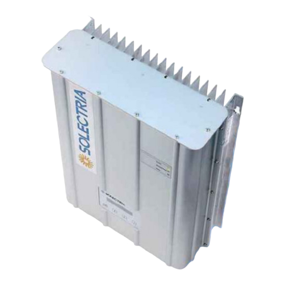
- Page 1 PVI 1800/PVI 2500 INSTALLATION AND OPERATION MANUAL Residential/Commercial Grid-Tied Photovoltaic Inverter © 2008, Solectria Renewables Subject to Change REV A...
-
Page 2: Important Safety Instructions
IMPORTANT SAFETY INSTRUCTIONS This manual contains important instructions that shall be followed during installation and maintenance of the PVI 1800/PVI 2500 Inverter. To reduce the risk of electrical shock, and to ensure the safe installation and operation of the inverter, the following safety symbols are used to indicate dangerous conditions and important safety instructions. - Page 3 ANSI/NFPA 70, NEC. The PVI 1800 and 2500 inverters are listed to UL1741/IEEE1547 (and comply with IEEE 62.41). The PVI 1800/PVI 2500 contains no user serviceable parts. Do not open the inverter case as this will damage the NEMA4, IP65 seal.
-
Page 4: Table Of Contents
PVI 1800/PVI 2500(Rev A) Installation and Operation Manual Table of Contents 1 Introduction ........................2 Installation ........................2.1 Checking for Shipping Damage ................2.2 Inverter Mounting ....................2.3 Electrical Connection and Connection to Electrical Utility Grid, Surge/Lightning Arrestors and Grounding Electrode Conductors ...... -
Page 5: Introduction
The PVI 1800/PVI 2500 is a residential/commercial single phase, grid-tied PV inverter designed to be inter-connected to the electric utility grid. With this manual the PVI 1800/PVI 2500 can be installed and operated safely. This installation guide is used as reference for the commissioning and as a guideline on how to use the inverter most effectively. - Page 6 The housing is designed to NEMA4 and IP65 to be dust-proof and resistant to water spray. The heat sink (and fan on the PVI 2500) are designed in such a way that operation of the inverter is possible at ambient temperatures of -4° F (–20° C) to +131° F (+55° C) at full rated power (at 240VAC or 208VAC).
- Page 7 Disconnecting from the grid is important to protect the electrical and utility line workers who may be working to restore the grid as well as electricians working at a site with PV systems. Power grid faults that will cause the PVI 1800/PVI 2500 to isolate itself from the power grid: AC grid voltage The grid voltage must not go outside the range of +10/-12% of the nominal 240 or 208V AC grid voltage (as per IEEE Std 1547, §...
- Page 8 PVI 1800/PVI 2500(Rev A) Installation and Operation Manual Diagram of the PVI 1800/PVI 2500 Features Fig. 2 PVI 1800/PVI 2500 Features Diagram (1) AC conduit fitting and conductors to building/grid (10 AWG, XHHW-2 wire) PV (2) PV array ground fault interrupt (GFDI) fuse...
-
Page 9: Installation
RMA# must be obtained from Solectria Renewables. 2.2 Inverter Mounting The PVI 1800/PVI 2500 inverter is made up of a sealed NEMA 4 /IP65 corrosion resistant aluminum enclosure containing all electrical and electronic components. - Page 10 PVI 1800/PVI 2500(Rev A) Installation and Operation Manual Notes regarding mounting and placement of the inverter Criteria for device mounting: Because the inverter is in a NEMA4/IP65 sealed enclosure, the inverter can be mounted outdoors. The very longest life for the inverter can be achieved by mounting it in a clean, dry and cool location even given the unit’s robust construction and design for efficient cooling.
- Page 11 PVI 1800/PVI 2500(Rev A) Installation and Operation Manual The ambient temperature must be between –4 F (–20 C) and +131 F (+55 C) for full continuous, full power operation. (The inverter will automatically reduce power or shut down to protect itself if...
- Page 12 PVI 1800/PVI 2500(Rev A) Installation and Operation Manual Fig. 4 PVI 1800/PVI 2500 Dimensional Diagram DOCR-070570-A...
- Page 13 PVI 1800/PVI 2500(Rev A) Installation and Operation Manual Fig. 5 PVI 1800/PVI 2500 Mounting Screw Pattern Mounting Details Using the mounting diagram Fig. 5, for screw positions on, wall. Four #10 or #12 screws can be used. It is recommended to use stainless steel screws, especially if used outdoors. Be sure to verify sheer and pullout strength of anchors or other wall attachments.
-
Page 14: Electrical Connection And Connection To Electrical Utility Grid
PVI 1800/PVI 2500(Rev A) Installation and Operation Manual NOTE: The inverter is set up with pre-wired AC and DC connections to make it very easy and quick to connect to a DC disconnect to the left of the inverter and an AC disconnect to the right. - Page 15 AC and DC (PV) Connections: The PVI 1800 and PVI 2500 inverters are pre-wired with 54” (1.35 meter) wires for both the DC (PV) input and the AC connection to the building/grid (so that a 48” long conduit can be used leaving 6” of conductors available for connection in the disconnect, junction box, etc.).
- Page 16 Installation and Operation Manual Multiple Units: Multiple PVI 1800 or PVI 2500 units can be used at the same location/facility assuming all codes are followed including NEC, local building codes and area utility guidelines. If multiple units are used, each inverter should have its own dedicated circuit breaker, and a PV string must only be wired to one inverter (although multiple PV strings can be used on each inverter up to unit ratings and power levels).
- Page 17 Connection Wiring To Electrical Utility Grid And Grid Impedance: The PVI 1800/PVI 2500 must be connected to the grid with 2 conductors and a ground wire. The grid impedance value at the connection point should be as low as possible to avoid an increase of the AC-voltage to non-permissible values while the inverter feeds to the grid.
- Page 18 NEC690-7 (1.25X PV OCV, for example) it may be adequate to use 250V DC rated disconnects as well. The PVI 1800 and PVI 2500 inverters are not capable of back-feeding currents into the PV array from the AC source including into short circuit(s) or fault(s) in the PV array or string(s). This allows some flexibility regarding PV string configurations including parallel strings with and without string fusing.
-
Page 19: Commissioning The Inverter And Pv System
PVI 1800/PVI 2500(Rev A) Installation and Operation Manual The PV-panel open circuit voltage must be below 400V DC (V < 400V DC) under all conditions as per NEC 690-7 using multiplier for cold weather OCV. Please read the Technical Info section and see PV string sizing table in Appendix C. - Page 20 The inverter operates automatically without the need for user interaction or maintenance. The PVI 1800/PVI 2500 automatically starts feeding AC power into the grid every morning as the sun rises, as soon as sufficient DC voltage and PV power is available. The inverter microcontroller runs through various checks before going online with the grid and feeding power into the grid.
-
Page 21: Power, Ground Fault, Error Led Indicators And Lcd Display
PVI 1800/PVI 2500(Rev A) Installation and Operation Manual 4.1 Power, Ground Fault and Error LED Indicators There are three light-emitting diodes (LEDs) mounted on the front (upper right corner) to show the operating condition of the inverter. Fig. 8: Power, Ground Fault and Error Indicator The green LED "Power"... - Page 22 PVI 1800/PVI 2500(Rev A) Installation and Operation Manual Operating condition Description LED indicator green: standby (night) input voltage < 120 VDC yellow: red: green: initialization unit is being initialized yellow: red: green: waiting, presence of valid grid conditions is yellow:...
-
Page 23: The Lcd Display
4.2 The LCD Display The PVI 1800/PVI 2500 inverter is supplied ready to operate so there are no settings, which have to be made by the user for fully automatic feeding of power into the grid. The device comes standard with a display on which various types of information can be read. -
Page 24: Main Menu
PVI 1800/PVI 2500(Rev A) Installation and Operation Manual Main menu The main menu is sub-divided into 6 menu items and each menu item contains sub-menus: - Menu N (Now) - Menu D (Day) - Menu W (Week) - Menu Y (Year) - Page 25 PVI 1800/PVI 2500(Rev A) Installation and Operation Manual Sub-menu N (Now) This menu item is used to view current values. ENTER 1. Menu-N Indication of the present 1. N > AC-Power power output xxxx W Indication of the present 2. N > AC-Voltage...
- Page 26 PVI 1800/PVI 2500(Rev A) Installation and Operation Manual Sub-menu D (Day) This menu item is used to call up daily values regarding power fed to the grid. ENTER 2. Menu-D Indication of the daily 1. D > Energy energy output...
- Page 27 PVI 1800/PVI 2500(Rev A) Installation and Operation Manual Sub-menu W (Week) This menu item is used to call up average values for the current week. ENTER 3. Menu-W Week Indication of the weekly 1. W > Energy energy output xxxx Wh Indication of the weekly 2.
- Page 28 PVI 1800/PVI 2500(Rev A) Installation and Operation Manual Sub-menu Y (Year) This menu item is used to call up average values for the current year. ENTER 5. Menu-Y Year 1. Y > Energy Indication of the annual energy output xxxx kWh Indication of the annual 2.
- Page 29 PVI 1800/PVI 2500(Rev A) Installation and Operation Manual Sub-menu S (Setup), the last line of the menu. The Setup menu serves to change the default settings of the PVI 1800/PVI 2500. ENTER 7. Menu-S Setup Inverter Setting the brightness 1. S > LCD-Contrast and contrast of the LCD 0 ..
-
Page 30: Troubleshooting
Diagnosis and analysing data Identifying and resolving faults The PVI 1800/PVI 2500 is fitted with a self-diagnostic system, which can recognise a majority of possible faults and show these on the display. This allows the operator to rapidly identify possible problems in the solar inverter or system. -
Page 31: Ground Fault
PVI 1800/PVI 2500(Rev A) Installation and Operation Manual arises on a regular basis Check the grid voltage The inverter switches over to normal power/feed mode as soon The installer/service technician Extreme grid over-voltage as the power grid voltage returns should be informed if this... - Page 32 PVI 1800/PVI 2500(Rev A) Installation and Operation Manual Overview error codes Code Designation Condition Solution The inverter resumes feeding the grid The service technician should be Hardware error, internal when automatic switching on of the informed if this error code has been...
-
Page 33: Warranty
120 months from date of purchase. If Solectria Renewables repairs or replaces a product, its warranty continues for the remaining portion of the original Warranty Period or 90 days from the date of the return shipment to the customer, whichever is greater. - Page 34 These warranties do not apply to and Solectria Renewables will not be responsible for any defect in or damage a) The product if it has been misused, neglected, improperly installed, physically damaged or altered, either internally or externally, or damaged from improper use or use in an unsuitable environment;...
- Page 35 A RESULT OF ANY USE, MISUSE OR ABUSE, OR THE (IN-) CORRECT INSTALLATION, INTEGRATION OR OPERATION OF THE PRODUCT. Solectria Renewables neither assumes nor authorizes any other person to assume for it any other liability in connection with the repair or replacement or the Product.
-
Page 36: Return Material Authorization Policy
2) Include the following: a. The RMA number supplied by Solectria Renewables, LLC clearly marked on the outside of the box b. A return address to which the unit can be shipped. Post office boxes are not acceptable. -
Page 37: Technical Data
PVI 1800/PVI 2500(Rev A) Installation and Operation Manual 7 Technical Data Technical Information and specifications – see PVI 1800/PVI 2500 brochure for various other information and data in addition to the information in this section of the manual. (see Appendix B for info). - Page 38 Output to AC grid connection: The PVI 1800/PVI 2500 is designed to feed power into a standard 60Hz, 240 or 208V AC utility service or 208V AC provided within a facility by a step down transformer (for example, from 480V AC service).
- Page 39 PVI 1800/PVI 2500(Rev A) Installation and Operation Manual Output (AC) specifications for PVI 1800/PVI 2500 Inverter: PVI 1800 PVI 2500 Continuous AC output power 1800 Watts AC 2500 Watts AC Operating voltage range +/- 10% 240/208V AC 240/208V AC Operating frequency range 59.3 to 60.5 Hz...
- Page 40 Fig. 11 AC Output power of PVI 1800/PVI 2500 DC input current versus DC input voltage Input current DC 1800W Input current DC 2500W DC Input Voltage (VDC) Fig. 12 Maximum continuous DC current input for PVI 1800/PVI 2500 DOCR-070570-A...
- Page 41 PVI 1800/PVI 2500(Rev A) Installation and Operation Manual 1200 1500 1800 Power (Watts) Fig. 13a PVI 1800 efficiency plot 1000 1500 2000 2500 Power (Watts) Fig. 13b PVI 2500 efficiency plot DOCR-070570-A...
-
Page 42: Appendices
PVI 1800/PVI 2500(Rev A) Installation and Operation Manual Appendices Appendix A: Terminal assignment RS-485 / RS-232: Not used RXD (RS232) TXD (RS232) GND (RS232/RS485) TERM (RS485) RX_B (RS485) TX_A (RS485) Not used Top view Hint! Both RJ45 connectors have the same pin-out. -
Page 43: Appendix B: Pvi 1800 / 2500 Brochure / Datasheet
Link: http://www.solren.com/downloads/PVI 1800_2500.pdf Appendix C Example string sizing PVI 1800/PVI 2500 (Note that the chart below is only to show how string sizing charts look. Please refer to the website version for complete and updated charts for use in all temperature zones across the country.) Updated string sizing tables are available on the website: www.solren.com... -
Page 44: Appendix D: Contact Information & Authorized Dealers And Installers
PVI 1800/PVI 2500(Rev A) Installation and Operation Manual Appendix D - Contact Information Solectria Renewables LLC 360 Merrimack Street Building 9 Lawrence, Massachusetts, 01843 Tel: 978.683-9700 Fax: 978.683-9702 Email: inverters@solren.com Website: www.solren.com Authorized Dealers and Installers – see website: www.solren.com Specific link: www.solren.com/distributors.html... - Page 45 PVI 1800/PVI 2500(Rev A) Installation and Operation Manual Appendix D – Certification to UL 1741 / IEEE 1547 / IEEE C62.41 DOCR-070570-A...
- Page 46 PVI 1800/PVI 2500(Rev A) Installation and Operation Manual DOCR-070570-A...
Need help?
Do you have a question about the PVI 2500 and is the answer not in the manual?
Questions and answers