Solectria Renewables PVI 10 KW Installation And Operation Manual
Hide thumbs
Also See for PVI 10 KW:
- Installation and operation manual (6 pages) ,
- Installation and operation manual (35 pages) ,
- Installation and operation manual (40 pages)

Subscribe to Our Youtube Channel
Related Manuals for Solectria Renewables PVI 10 KW


Summary of Contents for Solectria Renewables PVI 10 KW
- Page 1 PVI 10KW PVI 13KW PVI 15KW INSTALLATION AND OPERATION MANUAL Revision B ©2012, Solectria Renewables LLC All information subject to change without notice.
-
Page 2: Warranty Information
Installation and Operation Manual (Rev B) PVI 10KW, 13KW, 15KW IMPORTANT REGISTRATION AND WARRANTY INFORMATION For warranty to become active, this inverter must be registered. To activate warranty and register inverter, please visit the link below. www.solectria.com/registration... -
Page 3: Important Safety Instructions
Installation and Operation Manual (Rev B) PVI 10KW, 13KW, 15KW IMPORTANT SAFETY INSTRUCTIONS In this manual “inverter” or “inverters” refers to the inverter models: PVI 10KW, PVI 13KW, and PVI 15KW unless one of the specific models is noted. This manual contains important instructions that shall be followed during installation and maintenance of the inverter. - Page 4 Le PVI ne contient aucune pièce requérant un entretient effectué par l‘utilisateur. Pour toute maintenance, veuillez consulter Solectria Renewables ou un installateur agrée par Solectria Renewables (les coordonnées de Solectria Renewables et des installateurs agrées sont indiquées sur le site web de Solectria Renewables: www.solren.com.
-
Page 5: Table Of Contents
Installation and Operation Manual (Rev B) PVI 10KW, 13KW, 15KW Table of Contents Introduction ............................1 Site Preparation and Inverter Placement ..................3 Criteria for device mounting: ......................3 3.0 Inverter Mounting ........................... 5 Checking for Shipping Damage ..................... 5 Removing Inverter from Pallet and Moving Inverter into Place ........... -
Page 6: Introduction
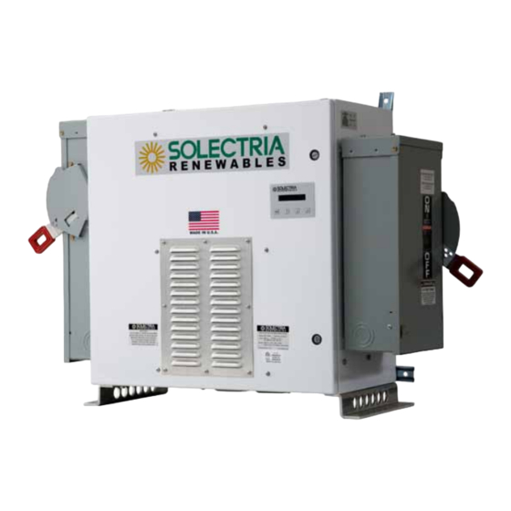
Installation and Operation Manual (Rev B) PVI 10KW, 13KW, 15KW 1.0 Introduction The PVI 10KW, PVI 13KW, and PVI 15KW are commercial, three-phase grid-tied PV inverters designed to be interconnected to the electric utility grid. By following this manual the inverter can be installed and operated safely. - Page 7 Installation and Operation Manual (Rev B) PVI 10KW, 13KW, 15KW Figure 1.2 – The PVI 10-15KW Inverter (Side Facing Disconnect Switches) (Front View) Figure 1.3 – The PVI 10-15KW Inverter (Forward Facing Disconnect Switches) (Front View) DOCR-060011...
-
Page 8: Site Preparation And Inverter Placement
Installation and Operation Manual (Rev B) PVI 10KW, 13KW, 15KW 2.0 Site Preparation and Inverter Placement The inverter is comprised of a rainproof, industrial enclosure containing electrical and electronic components and AC and DC integrated disconnects. NOTE: If the inverter is mounted outside, ensure that the enclosure doors remain closed during the installation process in case of rain or snow. - Page 9 Installation and Operation Manual (Rev B) PVI 10KW, 13KW, 15KW CAUTION: Please follow these guidelines: • Be sure to verify load capacity of floor, roof or wall mounting area. Inverter Model Weight PVI 10KW 357 lbs. PVI 13KW 357 lbs. PVI 15KW 357 lbs.
-
Page 10: Inverter Mounting
Please inspect the inverter thoroughly after it is delivered. If any damage is seen, immediately notify the shipping company to make a claim. If there is any question about potential shipping damage, contact Solectria Renewables. Photos of the damage will be helpful in documenting potential shipping damage. -
Page 11: Inverter Positioning And Mounting
Installation and Operation Manual (Rev B) PVI 10KW, 13KW, 15KW Inverter Positioning and Mounting Correct mounting position for the inverter is vertical with the mounting feet on the floor or back of inverter mounted to a wall. The PVI 10KW / PVI 13KW / PVI 15KW inverter is made up of a NEMA 3R industrial enclosure containing electrical and electronic components including transformer, filter, contactor, fusing, a sealed power &... - Page 12 Installation and Operation Manual (Rev B) PVI 10KW, 13KW, 15KW Figure 3.1 – The PVI 10-15KW Inverter Series Dimension (Front View) Figure 3.2 – The PVI 10-15KW Inverter Series Mounting Dimensions (Bottom View) DOCR-060011...
- Page 13 Installation and Operation Manual (Rev B) PVI 10KW, 13KW, 15KW Figure 3.3 – PVI 10-15KW Inverter Dimensions with Forward Facing Disconnect Switches (Front View) Figure 3.4 –PVI 10-15KW Inverter Dimensions with Forward Facing Disconnect Switches (Bottom View) DOCR-060011...
-
Page 14: Dc And Ac Connections
Installation and Operation Manual (Rev B) PVI 10KW, 13KW, 15KW 4.0 DC and AC Connections WARNING: All electrical installations shall be performed in accordance with all local electrical codes. Only make AC connections directly to the lugs within the AC disconnect switch and DC connections to the lugs within the DC disconnect switch or optional fused combiner. - Page 15 Installation and Operation Manual (Rev B) PVI 10KW, 13KW, 15KW For the DC wiring without an integrated fused PV combiner, two conductors are required (one for the grounded conductor and one for the ungrounded conductor) plus additional conductors for grounds (see section 4.1). 90°C copper conductors must be used. The disconnect switch terminals are listed for 75 C wire;...
-
Page 16: Dc Ground Fault Detection And Interruption
Installation and Operation Manual (Rev B) PVI 10KW, 13KW, 15KW WARNING: The PV grounded connections should not be bonded to the ground system at any point outside of the inverter. This bond is made in the GFDI circuit that is integral to the inverter. - Page 17 Installation and Operation Manual (Rev B) PVI 10KW, 13KW, 15KW disconnect switch terminals are listed for 75 C wire; see NEC 310.10 or Canadian Electrical Code regarding temperature ratings of wire and terminals. Temperature derates, voltage drop and other considerations may dictate that larger than minimum wire sizes be used. Verify that wire size choices meet local codes.
-
Page 18: Ac Ground Fault Detection
Installation and Operation Manual (Rev B) PVI 10KW, 13KW, 15KW entrance. With larger wires, the AC voltages at the inverter will be closer to the voltages at the point of interconnection, allowing for the most reliable inverter operation. The PVI series of inverters require a clockwise phase sequence for proper operation. - Page 19 Installation and Operation Manual (Rev B) PVI 10KW, 13KW, 15KW SolrenView is a state of the art web-based inverter monitoring data logger. The PVI series of inverters are equipped with SolrenView monitoring hardware as part of the display module. To activate the hardware, SolrenView monitoring services must be purchased from Solectria Renewables.
-
Page 20: Commissioning The Inverter
Installation and Operation Manual (Rev B) PVI 10KW, 13KW, 15KW 5.0 Commissioning the Inverter PV System Before commissioning, ensure that the inverter is mounted, all connections are made and the inverter is ready to power up. NOTE: Make sure all tools, parts, etc. are removed from the vicinity of the inverter before turning on. -
Page 21: Turning Off The Inverter
Installation and Operation Manual (Rev B) PVI 10KW, 13KW, 15KW Turning off the Inverter NOTE: IT IS CRITICAL THAT THE SEQUENCE FOR TURNING OFF THE INVERTER BE FOLLOWED EXACTLY. • Use the keypad to temporarily disable the power output. (Set Inverter Power Disable) •... -
Page 22: Lcd Display And Led Indicators
Installation and Operation Manual (Rev B) PVI 10KW, 13KW, 15KW 6.0 LCD Display and LED Indicators The inverter operates automatically without the need for user interaction. The LCD display and LED indicators on the front door of the inverter provide valuable inverter operating information. - Page 23 Installation and Operation Manual (Rev B) PVI 10KW, 13KW, 15KW Measurements Menu This displays the data retrieved from the inverter. Use the buttons to scroll up and down through the list. Pressing will take the screen back to the start menu. AC Energy Cumulative AC Energy (kWh) AC Power...
-
Page 24: Led Indicators
For other LED indications please contact Solectria Renewables Customer Support. 7.0 Troubleshooting and Inverter Messages Although the inverter is designed for many years of power production there may be instances where messages may be displayed on the LCD screen. -
Page 25: Inverter Messages
Installation and Operation Manual (Rev B) PVI 10KW, 13KW, 15KW 7.1 Inverter Messages The inverter is in derating mode. Can Check string sizing, ambient temp, fans operating, be caused by high input power, high vents are clear. Pac: XXXX W temperature, AC line impedance. - Page 26 Installation and Operation Manual (Rev B) PVI 10KW, 13KW, 15KW The inverter had a “UL event” and is Wait for the inverter to restart in the 5 minute wait period VAC Low Reconnecting Grid voltage may not be present Check for grid voltage Pac: XXXX W Waiting for grid The VAC grid connection phasing...
-
Page 27: Product Warranty & Rma Policy
60 months from the date of purchase of the inverter by the end user or 64 months after the delivery date from Solectria Renewables to the distributor or the dealer / installer, whichever is shorter. If a warranty extension has been purchased, the term is defined as an extension beyond 60 months. - Page 28 Limited Warranty. Solectria Renewables will, at its sole option, use new and / or reconditioned parts in performing warranty repair and/or replacements. Solectria Renewables reserves the right to use parts or products of original or improved design in the repair or replacement of the product.
- Page 29 Solectria Renewables product specifications including high input voltage from generators or lightning strikes; c) The product, if repairs have been made to it other than by Solectria Renewables or its authorized, trained service personnel;...
- Page 30 OF THE PRODUCT, REGARDLESS OF WHETHER SUCH INSTALLATION, INTEGRATION OR OPERATION WAS PERFORMED PROPERLY OR IMPROPERLY. Solectria Renewables neither assumes nor authorizes any other person to assume for it any other liability in connection with the repair or replacement of the Product.
-
Page 31: Return Material Authorization Policy
Please refer to your product user manual for limitations on uses of the product. Specifically, please note that Solectria Renewables’ products are not intended for use in connection with life support systems and Solectria Renewables makes no warranty or representation in connection with any use of the product for such purposes. - Page 32 A contact telephone number where you can be reached during work hours. A brief description of the problem. Ship the unit prepaid to the address provided by your Solectria Renewables’ customer service representative. Returning a product from outside of the USA or Canada: In addition to the above, you MUST include return freight funds and are fully responsible for all documents, duties, tariffs, and deposits.
-
Page 33: Technical Data
Installation and Operation Manual (Rev B) PVI 10KW, 13KW, 15KW 9.0 Technical Data Output AC Specifications The inverters are designed to feed power into a standard 60Hz, three-phase AC utility service provided within a facility by a transformer with a rating of not less than the rating of the inverter(s) connected to it. -
Page 34: Other Specifications
Installation and Operation Manual (Rev B) PVI 10KW, 13KW, 15KW Other Specifications DC Ground Fault Protection Per UL 1741 DC String Combiner Range 6/8/10/12/15/20A fuses available, 8 fused inputs DC Disconnect Switch(Integral) Break load rated, NEMA 3R ° ° ° Operational Ambient Temperature to 122°F (-40 to 50... - Page 35 Installation and Operation Manual (Rev B) PVI 10KW, 13KW, 15KW strike voltage (270 VDC) DC Voltage (VDC) Figure 9.1 – AC Output Power of PVI 10-15KW Series Inverters 225VDC 270VDC 380VDC 98.0% 97.0% 96.0% 95.0% 94.0% 93.0% 0.0% 20.0% 40.0% 60.0% 80.0% 100.0%...
-
Page 36: Internal Circuit Diagram
Figure 9.3 – Simplified Internal Circuit Diagram for PVI 10-15KW Series Inverters 10.0 Appendices 10.1 Appendix A – PVI 10-15KW datasheet http://www.solectria.com/?page_id=32 10.2 Appendix B – String Sizing Tool http://www.solectria.com/?page_id=30 10.3 Appendix C – Contact Information Solectria Renewables, LLC 360 Merrimack Street Building 9, 2 floor Lawrence, Massachusetts 01843 Tel: 978.683.9700 Fax: 978.683.9702... -
Page 37: Appendix D - Ul1741 / Ieee 1547 / Csa22.2#107.1 Listing Letter
Installation and Operation Manual (Rev B) PVI 10KW, 13KW, 15KW 10.5 Appendix D – UL1741 / IEEE 1547 / CSA22.2#107.1 Listing Letter DOCR-060011...
Need help?
Do you have a question about the PVI 10 KW and is the answer not in the manual?
Questions and answers