
Related Manuals for Solectria Renewables PVI 14TL


Summary of Contents for Solectria Renewables PVI 14TL
- Page 1 PVI 14TL PVI 20TL INSTALLATION AND OPERATION MANUAL Revision B ©2014, Solectria Renewables LLC YOUR SOLIGENT 800-967-6917 www.soligent.net...
-
Page 2: Warranty Information
Installation and Operation Manual (Rev B) IMPORTANT REGISTRATION AND WARRANTY INFORMATION For warranty to become active, this inverter must be registered. To activate warranty and register inverter, please visit the link below. www.solectria.com/registration... -
Page 3: Important Safety Instructions
Installation and Operation Manual (Rev B) IMPORTANT SAFETY INSTRUCTIONS In this manual “inverter” or “inverters” refers to the inverter models: PVI 14TL and PVI 20TL, unless one of the specific models is noted. This manual contains important instructions that shall be followed during installation and maintenance of the inverter. - Page 4 All electrical installations shall be performed in accordance with the local, American or Canadian electrical codes. The inverter contains no user serviceable parts. Please contact Solectria Renewables or a Solectria Renewables authorized system installer for maintenance. See Appendix C for Solectria Renewables contact information and authorized system installers.
-
Page 5: Table Of Contents
Installation and Operation Manual (Rev B) Table of Contents 1. Introduction .............................. 7 2. Site Preparation and Inverter Placement ....................11 2.1 Criteria for device mounting: ......................11 3. Inverter Mounting ........................... 12 3.1 Checking for Shipping Damage ......................12 3.2 Removing the Inverter from the Crate/Pallet and Moving the Inverter into Place ...... - Page 6 12.4 Temperature Derating Curve ......................56 12.5 Internal Circuit Diagram ........................56 13. Appendices ............................57 Appendix A – PVI 14TL-20TL datasheet ....................57 Appendix B – String Sizing Tool ....................... 57 Appendix C – Contact Information ......................57 Appendix D – Authorized Distributors ....................57...
-
Page 7: Introduction
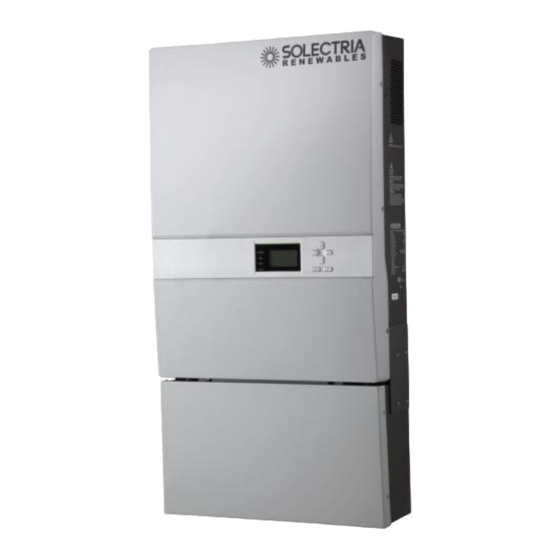
1. Introduction The PVI 14TL and PVI 20TL are commercial, dual MPPT, three-phase grid-tied transformerless PV inverters designed to be interconnected to the electric utility grid. The inverter is listed for use with ungrounded (floating) PV arrays only. By following this manual the inverter can be installed and operated safely. - Page 8 ⑥ AC disconnect Switch Built-in, lockable disconnect switch used to disconnect the AC output from the PV inverter. ⑦ Main housing (does not contain any serviceable parts, opening this section voids Inverters warranty) ⑧ Wiring Box Figure 1.2 – PVI 14TL Inverter Interface...
- Page 9 Installation and Operation Manual (Rev B) PVI 20TL Inverter Enclosure ① Control Keys There are 6 control keys to switch between display menus and to configure the settings on the LCD. ② LCD LCD screen displays all measured values and parameters. ③...
- Page 10 Installation and Operation Manual (Rev B) 8.46in 21.42in 215mm 544mm Figure 1.4 – PVI 14TL & PVI 20TL Inverter Dimensions...
-
Page 11: Site Preparation And Inverter Placement
PV array. CAUTION: Please follow these guidelines: Be sure to verify load capacity of wall or mounting area where the inverter would be mounted. Inverter Model Weight PVI 14TL 141 lbs. PVI 20TL 132 lbs. Table 2.1 – Inverter Weight... -
Page 12: Inverter Mounting
Please inspect the inverter thoroughly after it is delivered. If any damage is seen, immediately notify the shipping company to make a claim. If there is any question about potential shipping damage, contact Solectria Renewables. Photos of the damage will be helpful in documenting potential shipping damage. -
Page 13: Removing The Inverter From The Crate/Pallet And Moving The Inverter Into Place
Installation and Operation Manual (Rev B) 3.2 Removing the Inverter from the Crate/Pallet and Moving the Inverter into Place It is recommended to keep the inverter secured in the crate/pallet and move it as close as possible to the final location prior to removing the inverter from the crate/pallet. To remove the crate from pallet, unscrew the #2 Phillips screws from bottom of the crate while holding it on pallet. - Page 14 Installation and Operation Manual (Rev B) Do not install the inverter forward tilted, upside down or laying on its back (figure 3.2). Figure 3.2 Mounting of inverter – Not Allowed The minimum distances that must be met are shown in Figure 3.3 ...
- Page 15 Installation and Operation Manual (Rev B) Figure 3.3 Clearance Requirements Remove the side covers between the wiring box and the inverter section to get access to the handles in order to lift the inverter safely. At least two people are required to lift the inverter. Return side covers when mounting is complete.
- Page 16 Installation and Operation Manual (Rev B) Remove the two side covers prior to inverter installation as shown in Figure 3.5. Figure 3.5 Inverter Side Panels Install the inverter on the wall bracket and make sure that the top and bottom hooks of the inverter are engaged with the bracket as shown in Figure 3.6.
-
Page 17: Grounding Connections
Figure 4.1 DC input & equipment ground PVI 14TL and PVI 20TL inverters have a ground bar with four terminals used to terminate the equipment ground (Torque 25 in-lb) and one stud that fits M5 nut to terminate the AC ground (Torque for M5 nut is 10 in-lb). -
Page 18: Dc Connections From The Pv Array
Installation and Operation Manual (Rev B) 5. DC Connections from the PV Array WARNING: All wiring connections at the inverter must be performed with the building AC source circuit panel/breaker off and the PV module strings disconnected. AC and DC disconnect switches at the inverter must also remain of during termination. - Page 19 Installation and Operation Manual (Rev B) Figure 5.2 Diagram of Wire Connections For Use With Dual MPPT Zone The two MPPT zones can be combined by using the following configuration as shown in Figure 5.3. Jumper wire between J1 & J3 for positive terminals, jumper second wire between J2 & J4 for negative terminals.
- Page 20 Installation and Operation Manual (Rev B) 90°C copper conductors must be used for wiring. The inverter terminals are listed for 75 C wire; see NEC 310.10 or the Canadian Electrical Code regarding temperature ratings of wire and terminals. Temperature derating factors, voltage drop and other considerations may dictate that larger than minimum wire sizes be used.
- Page 21 Installation and Operation Manual (Rev B) inputs/ Configuration Type Proper Wiring Wire MPPT Zones PV1+ IN1+ IN1- PV1- 2 Inputs Inverter -2 MPPT IN2+ PV2+ Zones PV2- IN2- PV1+ IN1+ IN1- PV1- 2 Inputs Inverter 1 MPPT IN2+ PV2+ Zone PV2- IN2- PV1+...
-
Page 22: Ac Connections At The Inverter
Installation and Operation Manual (Rev B) 6. AC Connections at the Inverter For the 3-phase AC wiring, for both PVI 14TL and PVI 20TL, five conductors are recommended, one per phase along with a neutral and an AC equipment ground as per local requirements. 90°C rated copper conductors must be used. -
Page 23: Ac Interconnections To Grid
Installation and Operation Manual (Rev B) 6.1 AC Interconnections to Grid Description Configuration Inverter Compatibility 4 Wire WYE (3 phase + Compatible with 14TL Neutral +GND) Compatible with 20TL 3 Wire WYE (3 phase + Neutral jumper wire connected to GND at the Compatible with 14TL inverter) Compatible with 20TL... -
Page 24: Solrenview External Monitoring
Installation and Operation Manual (Rev B) 7. SolrenView External Monitoring PVI 14TL and 20TL inverters include an option for a SolrenView gateway integrated with the inverters wiring box. This device can be used for the purpose of monitoring and data logging. -
Page 25: Solrenview Logger Installation (If Not Pre-Ordered From The Factory)
Installation and Operation Manual (Rev B) 7.1 SolrenView Logger Installation (If not pre-ordered from the factory) WARNING: SolrenView gateway installation must be made by qualified personnel only. To reduce the risk of electric shock, you should never attempt to open the inverter, DC, or AC enclosure doors, or perform any service or troubleshooting without prior training. - Page 26 Installation and Operation Manual (Rev B) 2. Connect the SolrenView Monitoring Harness to the bottom of the SolrenView Gateway by plugging the six pin Molex connection into the bottom of the Gateway. The connector is keyed, so it cannot be installed incorrectly. Connectors are as follows: 3.
-
Page 27: One Gateway (Several Inverters)
Installation and Operation Manual (Rev B) 7.2 One Gateway (Several Inverters) For multiple inverters at one location it is possible to use one gateway with several inverters. Connect inverter’s RS 485 together using standard RJ 45 Ethernet patch cords and plugging these into RJ 45 jacks at each inverter on right side of wiring board. - Page 28 Installation and Operation Manual (Rev B) 7.4 Button Descriptions The SolrenView HMI is controlled by four buttons. These buttons are operated by momentarily pushing the center of the button. The buttons perform the following functions: To move up a level from the current menu. To cancel changing a data value.
-
Page 29: Establishing Ethernet Connectivity
Installation and Operation Manual (Rev B) 7.5 Accessing the Menu From the Main Display press the ENTER button to access the menu. Figure 7.6 Main Menu The Main Menu allows the user to configure and monitor the inverter. The selected menu option is shown with an arrow on the left. Please note that the display only shows two menu options at a time and will scroll to show the other options. -
Page 30: Setting Up Tcp/Ip Networking
Installation and Operation Manual (Rev B) 7.7 Setting up TCP/IP Networking Connection to the Internet and to the SolrenView web-based monitoring service requires a functioning TCP/IP protocol. This protocol runs over twisted pair Ethernet wiring and requires certain connections to properly operate. By default the SolrenView gateway should automatically configure TCP/IP address from a network router by using the DHCP protocol. -
Page 31: Manually Configuring Network Settings
Installation and Operation Manual (Rev B) 4. If the network is not working on the Ethernet protocol level, such as if the twisted pair Ethernet cable is not plugged in, the following will be displayed: Manually Configuring Network Settings To manually configure network settings: 1. -
Page 32: Automatically Configuring Network Settings
Installation and Operation Manual (Rev B) 8. Press the DOWN button to access the Gateway setting. Change in the same manner that the Static IP was modified. 9. Press the DOWN button to access the Netmask setting. Change in the same manner that the Static IP was modified. Automatically Configuring Network Settings When shipped from the factory, the SolrenView gateway uses DHCP to configure the TCP/IP settings. - Page 33 Installation and Operation Manual (Rev B) the octet. Press the ESCAPE button to cancel entry at any point. When the fourth octet is entered the entry will be saved. 7. Press the DOWN button to show the Gateway IP setting. 8.
-
Page 34: Enabling Solrenview Web-Based Monitoring
Installation and Operation Manual (Rev B) 7.8 Enabling SolrenView Web-based Monitoring Before SolrenView web-based monitoring can function the inverter must be networked to the Internet, see sections 6.12 through 6.15 for more details. As explained in section 6, data logging is one of the main functions of the SolrenView gateway. This option is turned on with the SRV Mode setting. -
Page 35: Rebooting The Solrenview Gateway
Installation and Operation Manual (Rev B) To view the date and time: 1. First select Config on the Main Menu then press ENTER. 2. Select the Date/Time option on the Config Menu then press ENTER. 3. The current date will be displayed. Note: The date is only editable if SRV Mode is off. -
Page 36: Hmi Menu Structure
Installation and Operation Manual (Rev B) To reset the SolrenView gateway: 1. First select Config on the Main Menu then press ENTER. 2. Select the Reset All option from the menu then press ENTER. 3. A message warning that the SolrenView gateway is about to be set to factory defaults will be shown. -
Page 37: Commissioning The Inverter Pv System
Installation and Operation Manual (Rev B) 8. Commissioning the Inverter PV System Before commissioning, ensure that the inverter is mounted, all connections are made and the inverter is ready to power up. NOTE: Make sure all tools, parts, etc. are removed from the vicinity of the inverter before turning on. -
Page 38: Lcd And Led Indicators
Installation and Operation Manual (Rev B) 9. LCD and LED Indicators The inverter operates automatically without the need for user interaction. The LCD display and LED indicators on the front of the inverter provide valuable operating information. 9.1 LCD Figure 9.1 – LCD Description Definition of function Escape key... -
Page 39: Screen Descriptions
Installation and Operation Manual (Rev B) 9.2 Screen Descriptions Main Screen (Default) Press appropriate keys to move from the main/default screen into the start menu. Start Menu Measurements Alarm History Settings Power/PF Measurements Menu This menu displays the data stored in the inverter memory. Use the buttons to scroll up and down through the list. - Page 40 Installation and Operation Manual (Rev B) NoError 2 Alarm EepromErr Protect0010 … Figure 9.3 Present fault information History Menu This menu displays inverter data history, some of which may be modified with the keypad. Use buttons to scroll up and down through the list. Pressing will take the screen back to the start menu.
- Page 41 Installation and Operation Manual (Rev B) NoError 1.St2010.12.15 20:50 SPI CommError 2.Ed2010.12.15 20:59 IntProtect1 … Enter day offset RunT - -h 1 ErrHist Energy - -KW 2 Recent Data ←2→ ß—12/15 Pmax - -KWh 3 History 3 Version →4 Etot Mach Ver Serial Number Etot (KWh)...
-
Page 42: Settings Menu
Installation and Operation Manual (Rev B) Settings Menu The inverter parameters can be adjusted by using commands in the settings menu as shown in the figure 9.5 below: → ON 1 Power ON/OFF → 1 中文 2 Language 2 English 3 Sounds 4 Setting →4 SysTime... -
Page 43: Led Indicators
Installation and Operation Manual (Rev B) Power /PF “Active Power” and “PowerFactor” parameters can be set up through the LCD keys as well as remotely. Note: Only adjustable with permission of the local utility 9.3 LED Indicators The LED indicators on the front of the inverters enclosure are used as indicators of the inverters operational status. -
Page 44: Troubleshooting And Inverter Messages
Installation and Operation Manual (Rev B) 10. Troubleshooting and Inverter Messages Although the inverter is designed for many years of power production there may be instances where error messages may are displayed on the LCD screen. This table can be used to help identify the error and resolve it. - Page 45 Installation and Operation Manual (Rev B) 1- Observe for 5 minutes and see whether the alarm is cleared automatically 1- Fan is blocked 2- Switch off the inverters internal disconnects One of the three external Alarm 4-ExtFanErr fans is not 2- Fan service life has 3- Check the fan blades operating...
- Page 46 Installation and Operation Manual (Rev B) 1- Observe for 10 minutes and see whether the 1- Grid voltage is abnormal alarm is cleared automatically 2- No AC voltage at the 2- Verify Grid Voltage is Grid voltage inverter within range Protection 2- GridV.OutLim exceeds the...
- Page 47 Installation and Operation Manual (Rev B) 1- Verify DC voltage DC inputs polarity is correct on all 1- PV positive pole and inputs connected with Protection 5- PV1 (2) Reverse negative pole are incorrect connected in reverse 2- If error does not clear, polarities contact Solectria Customer Service...
-
Page 48: Product Warranty And Rma Policy
Solectria Renewables Warranty Coverage: Solectria Renewables Limited Warranties are provided by Solectria Renewables, LLC. ("Solectria Renewables") and cover defects in workmanship and materials. Solectria Renewables’ price for the products is based on inclusion of these limited warranty provisions and disclaimers. In the event of a conflict between the terms of this Limited Warranty and any terms and conditions proposed by purchasers of Solectria Renewables’... - Page 49 Installation and Operation Manual (Rev B) Warranty start date: Solectria Renewables warranty begins on the date of shipment to the end user, or no later than 4 months from the date of shipment by Solectria Renewables. Duration of Solectria Renewables Extended Warranty Period: If a warranty extension has been purchased, the term is defined as an extension beyond the initial Standard Warranty period 5 years (60 months).
- Page 50 Within the Continental United States and Canada: Solectria Renewables warranty on three – phase inverters 10kW and higher (excluding TL products) covers parts, travel and labor necessary to repair the product and shipment of parts to and from the customer via a Solectria Renewables- selected non-expedited surface freight.
- Page 51 Solectria Renewables product specifications including high input voltage from generators or lightning strikes; c) The product, if repairs have been made to it other than by Solectria Renewables or its authorized, trained service personnel;...
- Page 52 REGARDLESS OF WHETHER SUCH INSTALLATION, INTEGRATION OR OPERATION WAS PERFORMED PROPERLY OR IMPROPERLY. Solectria Renewables neither assumes nor authorizes any other person to assume for it any other liability in connection with the repair or replacement of the Product. Installation and Operation Manual...
-
Page 53: Return Material Authorization Policy
2) Include the following: a. The RMA number supplied by Solectria Renewables clearly marked on the outside of the box. b. A return address to which the unit can be shipped. Post office boxes are not acceptable. - Page 54 A contact telephone number where you can be reached during work hours. d. A brief description of the problem. Ship the unit prepaid to the address provided by your Solectria Renewables’ customer service representative. Returning a product from outside of the USA or Canada: In addition to the above, you MUST include return freight funds and are fully responsible for all documents, duties, tariffs, and deposits.
-
Page 55: Technical Data
The inverter is designed to work with the range of AC voltages for a three-phase service defined by IEEE 1547-2003 and ANSI C84.1. PVI 14TL PVI 20TL Unit... -
Page 56: Input Dc (Pv) Specifications
Table 12.4 – DC Input Specifications 12.4 Temperature Derating Curve Power Level Ambient Temperature 12.5 Internal Circuit Diagram The basic power flow within the PVI 14TL-20TL series of inverters is below. Note that the GFDI circuit is not depicted. DC_Switch AC_Switch Filter PV1+... -
Page 57: Appendices
Installation and Operation Manual (Rev B) 13. Appendices Appendix A – PVI 14TL-20TL datasheet http://www.solren.com/datasheets/PVI_14-28TL_Datasheet.pdf Appendix B – String Sizing Tool http://www.solren.com/stringSizing.html Appendix C – Contact Information Solectria Renewables LLC 360 Merrimack Street Building 9, 2 floor Lawrence, Massachusetts 01843 Tel: 978.683.9700... - Page 58 Installation and Operation Manual (Rev B)
Need help?
Do you have a question about the PVI 14TL and is the answer not in the manual?
Questions and answers