Spektrum DX7 User Manual
7-channel, 20-model memory full range dsm2 system
Hide thumbs
Also See for DX7:
- Instruction manual (56 pages) ,
- Assembly manual (2 pages) ,
- Manual (115 pages)
Table of Contents
Advertisement
Quick Links
Advertisement
Table of Contents

Related Manuals for Spektrum DX7


Summary of Contents for Spektrum DX7
- Page 1 ® ® 7-Channel, 20-Model Memory Full Range DSM2 ™ System...
-
Page 2: Welcome To The World Of Spektrum Dsm2 Full Range Technology
Welcome to the World of Spektrum DSM2 Full Range Technology Spektrum’s DX7 is the first-ever full range 2.4Ghz Spread Spectrum Radio system for R/C aircraft. With Spektrum’s DSM2 ™ technology, now even large gas- and glow-powered aircraft can take advantage of Spektrum technology. -
Page 3: Dsm2 Dualink Technology
AR6000 Parkflyer Compatible You’ll be glad to know that the DX7 is compatible with the AR6000 mini park flyer receiver, however, when using the AR6000 receiver, aircraft type is limited to parkflyers and mini and micro helicopters only. Simply bind the DX7 transmitter to the AR6000 and you are ready to fly. -
Page 4: Model Match
The DX7 features Model Match technology that prevents the operation of a model if the wrong model memory is selected. During binding, the receiver actually learns and remembers the specific model memory (1 of 20) that the transmitter is currently programmed to. -
Page 5: Table Of Contents
Table of Contents Welcome to the World of Spektrum DSM2 Full Range Technology ............2 DSM2 DuaLink Technology ........................3 AR6000 Parkflyer Compatible .........................3 Model Match ............................4 Using This Manual ..........................4 Alternate Languages ..........................4 Battery Charging ...........................10 Transmitter/Receiver ........................10 Transmitter Polarity ........................10 Charger ............................10... - Page 6 V-Tail Type Servo Connections .....................41 Function Mode ..........................42 To Enter Function Mode ......................42 Function Mode Flowchart ........................43 Function List Modes ........................44 To Enter the Function List Mode ...................44 To Exit the Function List Mode .....................44 SPEKTRUM DX7 • TABLE OF CONTENTS...
- Page 7 System Setup Mode ..........................66 To Enter the System Setup Mode ..................66 To Exit the System Setup Mode ....................66 Model Select/Copy ........................67 To Enter the Model Select Function ..................67 To Enter the Copy Function ....................67 SPEKTRUM DX7 • TABLE OF CONTENTS...
- Page 8 To Access the Travel Adjust Function ..................84 Swashplate Mixing ........................85 Accessing the Swashplate Mix Function ................85 Throttle Hold ..........................86 To Access the Throttle Hold Function ...................86 To Access the Throttle Hold Switch Function ................86 SPEKTRUM DX7 • TABLE OF CONTENTS...
- Page 9 Three Year Warranty Period .........................103 Limited Warranty ..........................103 Damage Limits ............................103 Safety Precautions ..........................103 Questions, Assistance, and Repairs ....................104 Inspection or Repairs ..........................104 Warranty Inspection and Repairs ......................104 Non-Warranty Repairs .........................104 Aircraft Programming Guide .......................106 Helicopter Programming Guide......................107 SPEKTRUM DX7 • TABLE OF CONTENTS...
-
Page 10: Battery Charging
The pilot lamps should always be ON during the charging operation. If they’re not, check to make sure that both the transmitter and receiver are switched OFF. Do not use this charger for equipment other than Spektrum. The charging plug polarity may not be the same and equipment damage can result. During the charging operation, the charger’s temperature is slightly elevated. -
Page 11: Control Stick Tension Adjustment
IS KEYED SO THAT IT CAN ONLY BE PLUGGED IN ONE DIRECTION. DO NOT FORCE. Note: Use care when installing the screws securing the back of the transmitter. They are threading into plastic and can be stripped if over-tightened. SPEKTRUM DX7 • INTRODUCTION... -
Page 12: Adjusting The Control Stick Tension
AILERON TENSION SCREW SCREW Control Stick Length Adjustment The DX7 allows you to adjust the control stick’s length. Use the 2mm Allen wrench (supplied with SETSCREW your DX7 transmitter) to unlock the setscrew. Turn the wrench counterclockwise to loosen the screw. -
Page 13: Screen Contrast
Advanced Digital Trims The DX7 employs digital trim levers on aileron, elevator, throttle, and rudder. (Hover pitch and hover throttle for helicopters). The ADT (Advanced Digital Trim) feature is designed to automatically store the selected trim values for each model. When a different model is selected, the previously stored trim positions for that model are automatically recalled. -
Page 14: Receiver And Servo Installation
6” extension. By locating these receivers in slightly different locations in the aircraft, each receiver is exposed to its own RF environment, greatly improving path diversity (the ability for the receiver to see the signal in all conditions). SPEKTRUM DX7 • INTRODUCTION... -
Page 15: Receiver Installation
Receiver Installation Install the main receiver using the same method you would use to install a conventional receiver in your aircraft. Typically, wrap the main receiver in protective foam and fasten it in place using rubber bands or Velcro straps. Alternately, in electric models or helicopters, it’s acceptable to use thick double-sided foam tape to fasten the main receiver in place. - Page 16 Receiver Installation (continued) In helicopters, there is generally enough room on the servo tray to achieve the necessary separation. If necessary a mount can be fashioned using clear plastic to mount the external receiver.
-
Page 17: Servo Installation
Before each flying session, and especially with a new model, it is important to perform a range check. The DX7 incorporates a range testing system which, when the bind button on the back of the transmitter is pressed and held, reduces the output power, allowing a range check. -
Page 18: Binding
Binding The AR7000 receiver must be bound to the transmitter before it will operate. Binding is the process of teaching the receiver the specific code of the transmitter so it will connect to that specific transmitter. Once bound, the receiver will only connect to the transmitter when the previously bound model memory is selected. If another model memory is selected, the receiver will not connect. - Page 19 6. After you’ve programmed your model, it’s important to rebind the system so the true low throttle and neutral control surface positions are programmed. Note: The AR7000 features DSM2 ™ technology and is only compatible with DSM2 transmitters. The AR7000 will not operate with the DX6 or Spektrum ® surface systems. SPEKTRUM DX7 • INTRODUCTION...
-
Page 20: Airplane Quick Start
SERVO REVERSINg. (Page 21) HELI is highlighted, press the INCREASE or DECREASE key once and ACRO should be highlighted. Press the CLEAR key to accept the model type change. SPEKTRUM DX7 • AIRCRAFT QUICK START gUIDE... -
Page 21: Servo Reversing
Press the UP or DowN key until REVERSINg SW appears on screen. Press the SELECT key to select the desired channel, then press the INCREASE or DECREASE key to select reverse or normal servo direction. SPEKTRUM DX7 • AIRCRAFT QUICK START gUIDE... -
Page 22: Travel Adjust
Mixing, etc, see the appropriate pages listed in the table of contents. Note: If your airplane’s ailerons are controlled independently by two servos, see “Wing Type Selection” on Page 39 for specifics on programming flaperons. SPEKTRUM DX7 • AIRCRAFT QUICK START gUIDE... -
Page 23: Helicopter Quick Start
SERVO REVERSINg. (Page 24) ACRO is highlighted, press the INCREASE or DECREASE key once and heli should be highlighted. Press the CLEAR key to accept the model type change. SPEKTRUM DX7 • HELICOPTER QUICK START gUIDE... -
Page 24: Servo Reversing
Press the SELECT key to select the desired channel, then press the INCREASE or DECREASE key while holding the stick or switch in the desired direction that you wish to adjust the servo travel. SPEKTRUM DX7 • HELICOPTER QUICK START gUIDE... -
Page 25: Pitch Curve
Adjusting the Normal Pitch Curve The DX7 offers four independent pitch curves, each with up to five adjustable points. This function allocates a separate pitch curve setting during normal, stunt 1, stunt 2 and hold modes. Once the pitch curves are adjusted, each can be activated in flight using the three-position flight mode and throttle hold switches. -
Page 26: Throttle Curve
Note: For more information about setting up Throttle Curves see Page 87. This completes the basic Quick Start setup for your helicopter. For additional features like Dual and Expo Rates, Mixing, etc, see the appropriate pages listed in the table of contents. SPEKTRUM DX7 • HELICOPTER QUICK START gUIDE... -
Page 27: Aircraft Programming Guide
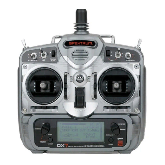
Flap Mix AUX 2 Switch Elevator Dual Rate Aileron Throttle Trim Dual Rate Elevator Trim Throttle/ Aileron/Elevator Rudder Stick Stick Aileron Trim Rudder Trim Increase/Decrease Button Up/Down Scroll Button Clear Key Select Key LCD Display SPEKTRUM DX7 • AIRCRAFT PROgRAMMINg gUIDE... -
Page 28: General Information
• The SELECT key is used to select the channel or feature that you wish to program. • The INCREASE or DECREASE keys are used to change the values of the selected programming feature. The DX7 features two programming modes: System Mode and Function Mode. SPEKTRUM DX7 • AIRCRAFT PROgRAMMINg gUIDE... -
Page 29: System Mode Functions
Use the UP and DowN keys to Scroll through the available function. Press DowN and SELECT to enter a selected function. In this mode, servos are not activated. By pressing the DowN and SELECT keys twice simultaneously, you can return to the main screen. SPEKTRUM DX7 • AIRCRAFT PROgRAMMINg gUIDE... -
Page 30: System Setup Mode Flowchart
• The system will display the last screen that was used in system set up mode. You are now in System Mode. To Exit the System Setup Mode • Press the DowN and SELECT keys simultaneously. The main screen will be displayed. • Turn the transmitter off. SPEKTRUM DX7 • AIRCRAFT PROgRAMMINg gUIDE... -
Page 31: Model Select/Copy Function
Model Select/Copy Function The DX7 features a memory function that stores the programmed data for up to 20 models. Any combination of up to 20 airplanes and/or helicopters can be stored in memory. A model name feature with up to eight characters allows each model to be easily identified. -
Page 32: To Enter The Copy Function
Press the CLEAR key to copy the model to the selected model memory. Note: Be aware that the model you copy to will have its memory replaced with the new model’s memory, and the programming information for the model to be copied to will be erased. SPEKTRUM DX7 • AIRCRAFT PROgRAMMINg gUIDE... -
Page 33: Model Name
Press the SELECT key to move the cursor to the desired character’s position. Press the INCREASE or DECREASE key to select the desired character. Model Match The DX7 features patented Model Match ™ technology that prevents operating a model using the wrong memory. -
Page 34: Type Select Function
Type Select Function The DX7 features two programming types: Airplane and Helicopter. The DX7 can memorize data for up to 20 models individually and the model type will automatically be stored with each model memory. Press to enter INCREASE and DECREASE key... -
Page 35: Model Reset And Integrated Timer Reset
When DATA RESET is selected, pressing the CLEAR key will reset the date to the factory default setting for that INTEg-T model, or if is selected, the integrated timer will be reset to 0:00:00. SPEKTRUM DX7 • AIRCRAFT PROgRAMMINg gUIDE... -
Page 36: Trainer
(aileron, elevator, rudder and throttle) are transferred to the slave transmitter when the trainer switch is pressed. SLAVE/P-LINK: In the Slave mode, the DX7 is used as a slave radio in conjunction with a Spektrum ® radio that is used as the master that is in P-LINK mode;... -
Page 37: Throttle Recovery
Throttle Recovery The DX7 has a unique throttle trim recovery feature. Throttle Recovery stores the last known throttle trim position before the trim is moved to the full down (closed) position. That stored position is then recalled by moving the throttle trim up (open) one notch. This makes shutting off the engine and restarting it with the correct trim position easy. -
Page 38: Input Select
Note: When operating the transmitter in a trainer mode (Normal or P-Link Master) the Trainer- Flap Rocker is not available to control the flaps. Note: The individual AUX2/spoiler operation is inhibited when AUX2/spoiler is coupled for automatic landing attitude. SPEKTRUM DX7 • AIRCRAFT PROgRAMMINg gUIDE... -
Page 39: Wing Type
Wing Type The DX7 offers three different wing types to choose from: Normal, Flaperon and Delta (also called elevon mixing). In addition, V-Tail mixing is available from the Wing Type screen. Normal When the Flaperon and Delta wing function are off, Normal wing type is selected. Use this wing type with common aircraft that utilize only one servo for both ailerons. -
Page 40: To Select A Wing Type
It is also possible to set aileron differential. Reverse switches are applicable for each servo. Neutral adjustments of each servo are made by the Sub Trim Function. SPEKTRUM DX7 • AIRCRAFT PROgRAMMINg gUIDE... -
Page 41: Flaperon Wing Type Servo Connections
ELEV Servo Port (Left Aileron) (Right Aileron) V-Tail Type Servo Connections • RUDD servo port (right V-tail) • ELEV servo port (left V-tail) V-Tail Type Connection ELEV Servo Port RUDD Servo Port (Left V-Tail) (Right V-Tail) SPEKTRUM DX7 • AIRCRAFT PROgRAMMINg gUIDE... -
Page 42: Function Mode
• Use the INCREASE and DECREASE keys to change the values or positions of the selected channel. • Use the CLEAR key is used to return the selected value to the factory default settings. SPEKTRUM DX7 • AIRCRAFT PROgRAMMINg gUIDE... -
Page 43: Function Mode Flowchart
Elevator-to-Flap Mix Differential FLAPERON ◊RATE:≥D (Page 51) (Page 55) NORM SW:FLAP0 [AILE->RUDD MIX] [FLAP SYS.] NORM FLAP ELEV Aileron-to-Rudder Mix Flap System ◊RATE: NORM ◊UP100% (Page 52) (Page 53) SW: MIX DN100% LAND AUTO SPEKTRUM DX7 • AIRCRAFT PROgRAMMINg gUIDE... -
Page 44: Function List Modes
• Press DowN and SELECT to enter a selected function. To Exit the Function List Mode • Press the DowN and SELECT keys simultaneously twice. The system will return to the main screen or turn off the transmitter. SPEKTRUM DX7 • AIRCRAFT PROgRAMMINg gUIDE... -
Page 45: Dual Rate And Switch Select
Press the UP or DowN key until D/R SWITCH SEL appears on the screen. Press the INCREASE or DECREASE keys to select the desired switch(es) you wish to operate the D/R and Expo function. SPEKTRUM DX7 • AIRCRAFT PROgRAMMINg gUIDE... -
Page 46: Function Mode Functions
(COM AILE, COM ELEV, COM RUDD, FLAP0 or FLAP2). The choices for this are found on the D/R SWITCH SEL screen in the System Setup Mode for Airplanes. (See Page 45) SPEKTRUM DX7 • AIRCRAFT PROgRAMMINg gUIDE... -
Page 47: To Adjust The Exponential
Move the selected channel’s dual rate switch to the desired position, 0 or 1. Press the SELECT key until is highlighted. Adjust the Expo rate values for the selected switch position using the INCREASE or DECREASE keys. SPEKTRUM DX7 • AIRCRAFT PROgRAMMINg gUIDE... -
Page 48: Reverse Switch
Press the INCREASE or DECREASE keys to reverse the servo direction for that selected channel. The channels available are: • THRO: Throttle • AILE: Aileron • ELEV: Elevator • RUDD: Rudder • GEAR: Retractable Landing Gear • FLAP: Flap • AUX2: Auxiliary 2 SPEKTRUM DX7 • AIRCRAFT PROgRAMMINg gUIDE... -
Page 49: Sub-Trim
In Function Mode, use the UP or DowN key to select the SUB TRIM screen. Press the SELECT key to access the desired channel. Press the INCREASE or DECREASE keys to adjust the sub-trim position for that selected channel. SPEKTRUM DX7 • AIRCRAFT PROgRAMMINg gUIDE... -
Page 50: Travel Adjust
Press the SELECT key to access the desired channel. Move the selected channel’s stick or switch in the desired direction that you wish to adjust. Press the INCREASE or DECREASE keys to adjust the end-point position for that selected channel’s direction. SPEKTRUM DX7 • AIRCRAFT PROgRAMMINg gUIDE... -
Page 51: Elevator-To-Flap Mix Function
INCREASE or DECREASE button to adjust the desired mix value. To Select the Switch to Operate the Flap Mix Press the SELECT key to highlight SW. Press the INCREASE or DECREASE key to select the FLAP0 switch position. SPEKTRUM DX7 • AIRCRAFT PROgRAMMINg gUIDE... -
Page 52: Aileron-To-Rudder Mixing
Note: To reverse mix directions, a negative mix value is accessible. To Assign a Switch With highlighted, press the INCREASE or DECREASE keys to select the desired switch used to turn on/off the mix (Flap 0 or Mix). SPEKTRUM DX7 • AIRCRAFT PROgRAMMINg gUIDE... -
Page 53: Flap System
Press the UP or DowN keys to set the value for flap and elevator travel. The UP key adds up flap/elevator and the DowN key adds down flap/elevator. The input is adjustable from 125% for flap and -200% for elevator. SPEKTRUM DX7 • AIRCRAFT PROgRAMMINg gUIDE... -
Page 54: Automatic Landing
To change this value, press the INCREASE or DECREASE key to adjust the value (0% = low stick while 100% = full stick). To clear the auto land point, press CLEAR and the display will return to INH. SPEKTRUM DX7 • AIRCRAFT PROgRAMMINg gUIDE... -
Page 55: Differential Aileron Mixing
If differential is working in reverse, the aileron servos are plugged into the wrong (opposite) channels. The right aileron should be plugged into the aileron channel, while the left aileron should be plugged into the flap channel. SPEKTRUM DX7 • AIRCRAFT PROgRAMMINg gUIDE... -
Page 56: Programmable Mixing 1-6
Programmable Mixing 1–6 The DX7 offers six (6) programmable mixes that allow stick or switch inputs to control the output of two or more servos. This function allows mixing any one channel to any other channel, or the ability to mix a channel to itself. -
Page 57: Assigning Channels
Note: If a switch is assigned to the mix, that switch must be turned on to allow mixing values to be changed. Moving the stick or switch in the opposite direction will allow the mix value to be adjusted in the opposite direction. SPEKTRUM DX7 • AIRCRAFT PROgRAMMINg gUIDE... -
Page 58: Assigning An Offset
Use the INCREASE or DECREASE keys to select the desired switch to turn on/off the mix. • ON: Mixing Always On • MIX: Mixing Switch Toward Self • Flap 0: Flap Switch in Flap 0 Position • Flap 2: Flap Switch in Flap 2 Position • Gear: Gear Switch SPEKTRUM DX7 • AIRCRAFT PROgRAMMINg gUIDE... -
Page 59: Timer
Timer The DX7 features an onscreen timer with three programming options: INH: Inhibit- In this mode the timer is turned off. Down-T: Down Timer- The countdown timer allows a preset time in ten-second intervals up to 59 minutes and 50 seconds to be programmed, and when that time expires, a beeper will sound for 10 seconds. - Page 60 In System Mode use the UP or DowN key to select the TIMER screen. Press the SELECT key to select STOP-W, DOWN-T or INH. With DOWN-T selected press the INCREASE or DECREASE key to change the preprogrammed time. SPEKTRUM DX7 • AIRCRAFT PROgRAMMINg gUIDE...
-
Page 61: Servo Monitor
The servo monitor screen serves as a useful tool when programming your radio. It displays servo positions and is useful in checking different programming functions. Press to enter SERVO MONITOR THRO AILE ELEV RUDD GEAR FLAP AUX2 Press to enter Function Mode SPEKTRUM DX7 • AIRCRAFT PROgRAMMINg gUIDE... - Page 62 SPEKTRUM DX7 • AIRCRAFT PROgRAMMINg gUIDE...
-
Page 63: Helicopter Programming Guide
Carrying Handle Gear Switch Switch Elevator Dual Rate Aileron Throttle Trim Dual Rate Elevator Trim Throttle/ Aileron/Elevator Rudder Stick Stick Aileron Trim Rudder Trim Increase/Decrease Button Up/Down Scroll Button Clear Key Select Key LCD Display SPEKTRUM DX7 • HELICOPTER PROgRAMMINg gUIDE... -
Page 64: General Information
• The INCREASE or DECREASE keys are used to change the values of the selected programming feature. The DX7 features two programming modes: System Setup Mode and Function Mode, which are described in the next sections. SPEKTRUM DX7 • HELICOPTER PROgRAMMINg gUIDE... -
Page 65: Warning Screen For Throttle Hold/Stunt Mode
Warning Screen for Throttle Hold/Stunt Mode When the DX7 is operated in the helicopter mode, there is a warning system that is employed to avoid hot starts (accidental high throttle startups) when the power switch is initially turned ON. If the flight mode switch or throttle hold is on, an alarm will sound and a warning message will be displayed on the LCD. -
Page 66: System Setup Mode
• The system will display the last system setup screen that was used. To Exit the System Setup Mode • Press the DowN and SELECT keys simultaneously. • The main menu will be displayed • Or turn the transmitter off to exit the System Setup Mode. SPEKTRUM DX7 • HELICOPTER PROgRAMMINg gUIDE... -
Page 67: Model Select/Copy
Model Select/Copy The DX7 features a memory function that stores the programmed data for up to 20 models. Any combination of up to 20 airplanes and/or helicopters can be stored in memory. A model name feature with up to eight characters allows each model to be easily identified. -
Page 68: Model Name
Press the SELECT Key to move the cursor to the desired character’s position. Press the INCREASE or DECREASE key to select the desired character. Model Match The DX7 features patented Model Match ™ technology that prevents operating a model using the wrong memory. -
Page 69: Type Select Function
Type Select Function The DX7 features two programming types: Airplane and Helicopter. The DX7 can memorize data for up to 20 models individually. Press to enter INCREASE and DECREASE key TYPE SELECT [TYPE SELECT] MODEL 1 ◊HELI ACRO Hold while turning on transmitter To Enter the Type Select Mode Press the DowN and SELECT keys simultaneously, then turn on the transmitter. -
Page 70: Model Reset/Integrated Timer
• Press the UP key until the MODEL RESET function appears on screen. • Press the SELECT key until INTEg-T is highlighted. • Pressing the CLEAR key will reset the INTEg-T to factory zero. SPEKTRUM DX7 • HELICOPTER PROgRAMMINg gUIDE... -
Page 71: Trainer
(aileron, elevator, rudder and throttle) are transferred to the slave transmitter when the trainer switch is pressed. SLAVE/P-LINK: In the Slave mode, the DX7 is used as a slave radio in conjunction with a Spektrum ® radio that is used as the master that is in P-LINK mode;... -
Page 72: Throttle Recovery
Throttle Recovery The DX7 has a unique throttle trim recovery feature. Throttle Recovery stores the last know throttle trim position before the trim is moved to the full down (closed) position. That stored position is then recalled by moving the throttle trim up (open) one notch. This makes shutting off the engine and restarting it with the correct trim position easy. -
Page 73: Input Select
The gyro mode is selected if you want to use the Gyro Sensing (see page 91) for more detail. Selecting GYRO under AUX2 assigns the gyro sensing program to operate use the AUX2 channel. In this case the gyro gain must be plugged into the AUX2 (Channel 7) channel. SPEKTRUM DX7 • HELICOPTER PROgRAMMINg gUIDE... -
Page 74: To Select The Function For The Gear Channel
Gear is selected if the gyro gain or retractable gear position is to be selected using the gear switch. gYRO: Gyro is selected under gear if you wish to have the Gyro Sensing (Page 91) operate using the gear channel. AUX2: The Auxiliary 2 switch is used to activate the gear channel. SPEKTRUM DX7 • HELICOPTER PROgRAMMINg gUIDE... -
Page 75: Swash Type
Swash Type The Swashplate Mixing function enables the DX7 system to operate the following swashplate types: The Swashplates are: • 1 Servo: Non-CCPM, standard mixing type helicopter • 2 Servo/180° CCPM • 3 Servo/120° CCPM (most popular) • 3 Servo/90° CCPM... -
Page 76: Function Mode Flowchart
[PITCH CURVE] ST-1 ST-1 Throttle Curve ST-1 Pitch Curve ST-1 ≥Point-3 ≥Point-3 (Page 87) (Page 89) [THRO CURVE] [PITCH CURVE] NORM ST-2 Throttle Curve ST-2 Pitch Curve Normal ≥Point-3 ≥Point-3 (Page 87) (Page 89) SPEKTRUM DX7 • HELICOPTER PROgRAMMINg gUIDE... -
Page 77: To Enter The Function Mode
• The system is now in Function Mode and will display the last screen that was used in Function Mode. To Exit the Function Mode • Press the DowN and SELECT keys simultaneously. The system will return to the main screen. SPEKTRUM DX7 • HELICOPTER PROgRAMMINg gUIDE... -
Page 78: List Modes
CLEAR key UP and DOWN key INCREASE and DECREASE key [FUNCTION LIST] º PI CURV ST2 º PROG.MIX3 º TIMER º REVO. MIX ◊MONITOR º GYRO SENS º PROG.MIX1 º PROG.MIX2 SELECT key CLEAR key SPEKTRUM DX7 • HELICOPTER PROgRAMMINg gUIDE... -
Page 79: Function Mode Functions
The Dual Rate and Expo functions for aileron, elevator and rudder can be combined on the flight mode auto dual rate/expo conveniently allowing high or low rates to be selected via the flight mode switch. See Page 81 for more details. SPEKTRUM DX7 • HELICOPTER PROgRAMMINg gUIDE... -
Page 80: To Adjust The Exponential
Move the selected channel’s dual rate switch to the desired position, 0 or 1. Press the SELECT key until is highlighted. Adjust the Expo rate values for the selected switch position using the INCREASE or DECREASE keys. SPEKTRUM DX7 • HELICOPTER PROgRAMMINg gUIDE... -
Page 81: Auto Dual Rate Exp
When selected, press the INCREASE or DECREASE key to select DUAL RATE, P-1, or INHIBIT. Note: The actual dual rate values are set in the Dual Rate and Expo screen. See Page 79. SPEKTRUM DX7 • HELICOPTER PROgRAMMINg gUIDE... -
Page 82: Reverse Switch
Press the INCREASE or DECREASE keys to reverse the servo direction for that selected channel. • THRO: Throttle • AILE: Aileron • ELEV: Elevator • RUDD: Rudder • GEAR: Gyro Gain • PIT: Pitch (AUX1) Gyro Gain SPEKTRUM DX7 • HELICOPTER PROgRAMMINg gUIDE... -
Page 83: Sub Trim
In Function Mode, use the UP or DowN key to select the SUB TRIM screen. Press the SELECT key to access the desired channel. Press the INCREASE or DECREASE keys to adjust the sub-trim position for that selected channel. SPEKTRUM DX7 • HELICOPTER PROgRAMMINg gUIDE... -
Page 84: Travel Adjust
Press the SELECT key to access the desired channel. Move the selected channel’s Stick or switch in the desired direction that you wish to adjust. Press the INCREASE or DECREASE keys to adjust the sub-trim position for that selected channel’s direction. SPEKTRUM DX7 • HELICOPTER PROgRAMMINg gUIDE... -
Page 85: Swashplate Mixing
Press the SELECT key to access the desired function (AILERON, ELEVATOR, PITCH or EXPO). Press the INCREASE or DECREASE key to change the selected swashplate mix value. Note: Selecting a negative value will reverse the direction of the function. SPEKTRUM DX7 • HELICOPTER PROgRAMMINg gUIDE... -
Page 86: Throttle Hold
When activated, press the INCREASE or DECREASE key to change the throttle hold value. To Access the Throttle Hold Switch Function Press the SELECT key to highlight switch. Press the INCREASE or DECREASE key to select the desired switch. SPEKTRUM DX7 • HELICOPTER PROgRAMMINg gUIDE... -
Page 87: Throttle Curve
Throttle Curve The DX7 offers three (3) separate throttle curves with five (5) adjustable points per curve. This function allows you to adust the throttle curve to optimize engine rpm at a particular pitch setting. Once the throttle curves are established, each can be activated in flight using the 3-position flight mode switch. -
Page 88: Throttle Trim Setting
Stunt 1 or Stunt 2. Exponential Throttle Curve Function With the DX7 system, individual throttle curves are selectable to be either straight (linear) or curved (exponential). To select an exponential curve, press the select key until EXP OFF appears on the throttle curve screen. -
Page 89: Pitch Curve
A thorough understanding of the throttle curve section will make pitch curve adjustment easier to understand. The DX7 offers four (4) independent pitch curves: Normal, Stunt 1, Stunt 2 and Hold. Each pitch curve contains five (5) adjustable points — L, 1, 2, 3, and H. -
Page 90: Revolution Mixing (Only Used With Non-Heading Hold Gyros)
Because torque reaction varies with different power settings, it is necessary to vary the tail rotor pitch at the same time. The DX7 offers two (2) separate revolution mixing programs with independent up and down mixing for each—one for flight mode position N, and the other for Stunt 1 and Stunt 2 positions. -
Page 91: Gyro Sensing
Gyro Sensing The DX7 offers two different types of Gyro Sensitivity Adjustments — manual or automatic. This feature gives the user the choice of selecting gyro sensitivity manually through the rudder dual rate switch or automatically through the flight mode switch. -
Page 92: Programmable Mixing 1-3
Programmable Mixing 1–3 In helicopter mode the DX7 offers three (3) programmable mixes that allow stick or switch inputs to control the output of two or more servos. This function allows mixing any one channel to any other channel or the ability to mix a channel to itself. -
Page 93: Assigning Mixing Values
Note: If a switch is assigned to the mix, that switch must be turned on to allow mixing values to be changed. Moving the stick or switch in the opposite direction will allow the mix value to be adjusted in the opposite direction. SPEKTRUM DX7 • HELICOPTER PROgRAMMINg gUIDE... -
Page 94: Assigning An Offset
Move the master channel’s stick to the desired offset position and press the CLEAR key to store that offset value. The stored offset value will appear onscreen. To change the offset value, simply move the master channel’s stick to the desired position and press the CLEAR button. SPEKTRUM DX7 • HELICOPTER PROgRAMMINg gUIDE... -
Page 95: Timer
Timer The DX7 features an onscreen timer with three programming options: INH: Inhibit- In this mode the timer is turned off. DOWN-T: Down Timer- The countdown timer allows a preset time in ten-second intervals up to 59 minutes and 50 seconds to be programmed and when that time expires a beeper will sound for 10 seconds. -
Page 96: To Access The Timer Function
In System Mode use the UP or DowN key to select the TIMER screen. Press the SELECT key to select STOP-W, DOWN-T or INH. With DOWN-T selected press the INCREASE or DECREASE key to change the preprogrammed time. SPEKTRUM DX7 • HELICOPTER PROgRAMMINg gUIDE... -
Page 97: Servo Monitor
The servo monitor screen serves as a useful tool when programming your radio. It displays servo movement and direction when different programming functions, sticks and/or switches are moved. Press to enter SERVO MONITOR THRO AILE ELEV RUDD GEAR FLAP AUX2 Press to enter Function Mode SPEKTRUM DX7 • HELICOPTER PROgRAMMINg gUIDE... - Page 98 SPEKTRUM DX7 • HELICOPTER PROgRAMMINg gUIDE...
-
Page 99: General Information
For more information about where you can drop off your waste equipment for recycling, please contact your local city office, your household waste disposal service or where you purchased the product. USA Canada Belgium Denmark France Finland Germany Italy Netherlands Spain Sweden SPEKTRUM DX7 • gENERAL INFORMATION... -
Page 100: Servo Precautions
• Do not take chances. If at any time during flight you observe any erratic or abnormal operation, land immediately and do not resume flight until the cause of the problem has been ascertained and corrected. Safety can never be taken lightly. SPEKTRUM DX7 • gENERAL INFORMATION... -
Page 101: Federal Aviation Administration
Do not hesitate to ask for assistance in complying with these guidelines at the airport traffic control tower or air route traffic control center nearest the site of your proposed operation. Information Provided By Director, Air Traffic Service Federal Aviation Administration, Washington, D.C. SPEKTRUM DX7 • gENERAL INFORMATION... -
Page 102: Daily Flight Checks
6. Check that all trim levers are in the proper location. 7. All servo pigtails and switch harness plugs should be secured in the receiver. Make sure that the switch harness moves freely in both directions. SPEKTRUM DX7 • gENERAL INFORMATION... -
Page 103: Three Year Warranty Period
The Product manual contains instructions for safety, operation and maintenance. It is essential to read and follow all the instructions and warnings in the manual, prior to assembly, setup or use, in order to operate correctly and avoid damage or injury. SPEKTRUM DX7 • WARRANTY... -
Page 104: Questions, Assistance, And Repairs
All other Products requiring warranty inspection or repair should be shipped to the following address: Horizon Product Support 4105 Fieldstone Road Champaign, Illinois 61822 Please call 877-504-0233 with any questions or concerns regarding this product or warranty. SPEKTRUM DX7 • WARRANTY... - Page 105 SPEKTRUM DX7 • gENERAL INFORMATION...
-
Page 106: Aircraft Programming Guide
– MIX 2 – MIX 3 PROGRAM – MIX 4 – MIX 5 – MIX 6 AILERON FLAPERON WING ELEVATOR ELEVON TYPE SWITCH V-TAIL RUDDER SELECT FLAP 2 ELEV FLAP 0 FLAP SYSTEM FLAP SPEKTRUM DX7 • AIRCRAFT PROgRAMMINg gUIDE... -
Page 107: Helicopter Programming Guide
REV R•N REV R•N REV R•N FL-M CHANNEL +POS –POS OFFSET – MIX 1 PROGRAM – MIX 2 – MIX 3 AILE ELEV RUDD NORMAL DOWN REVO MIX DUAL RATE • STUNT DOWN EXPO SPEKTRUM DX7 • HELICOPTER PROgRAMMINg gUIDE... - Page 108 ® ® © 2006 Horizon Hobby, Inc. 4105 Fieldstone Road Champaign, Illinois 61822 (877) 504-0233 www.horizonhobby.com www.spektrumrc.com #9171...
Need help?
Do you have a question about the DX7 and is the answer not in the manual?
Questions and answers
wich does the DX7 use
The Spektrum DX7 uses DSM2™ (Digital Spread Spectrum Modulation) technology with DuaLink™, which operates on the 2.4GHz band. This technology provides full-range capability and is resistant to internal and external radio interference.
This answer is automatically generated
how do you clar memory on spektrum dx7
The Spektrum DX7 does not have a total system reset option. However, you can clear memory by zeroing out each model memory location separately or by overwriting it with new data.
This answer is automatically generated