Spektrum DX7 Manual
7-channel, 20-model memory full range
Hide thumbs
Also See for DX7:
- User manual (108 pages) ,
- Instruction manual (56 pages) ,
- Assembly manual (2 pages)
Table of Contents
Advertisement
Spektrum DX7 7-Channel, 20-Model Memory Full Range DSM2™ System ohjekirja
Sivu 2
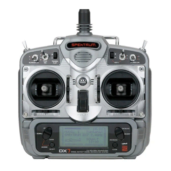
Spektrum's DX7 is the first-ever full range 2.4Ghz Spread Spectrum Radio system for R/C aircraft. With
Spektrum's DSM2
technology, now even large gas- and glow-powered aircraft can take advantage of
™
Spektrum
technology. No longer will you have to wait for a frequency pin or be concerned that someone may
®
inadvertently turn on to your same frequency. With Spektrum DSM2 technology, when you're ready to fly any
aircraft—from parkflyer to giant-scale—simply turn on the system, and go flying!
Spektrum DX7 on ensimmäinen täyden alueen 2,4 GHz Spektrumin radio-ohjauslaite R/C ilma-aluksille.
Nyt myös kaikki isot polttomoottorikäyttöiset ilma-alukset voivat saada täyden hyödyn Spektrumin
teknologiasta. Enää ei tarvitse odottaa taajuuden vapautumista, tai varmistusta sille, että joku toinen
olisi tulossa samalla taajuudella.
Spektrumin DSM2 teknologialla voit nyt heti kun olet valmiina – pienestä sisälentolaitteesta suureen
jumbokokoiseen laitteeseen asti – kytke vain virrat päälle ja aloita lennättäminen.
Advertisement
Table of Contents

Related Manuals for Spektrum DX7


Summary of Contents for Spektrum DX7
- Page 1 Spektrum DX7 7-Channel, 20-Model Memory Full Range DSM2™ System ohjekirja Sivu 2 Spektrum’s DX7 is the first-ever full range 2.4Ghz Spread Spectrum Radio system for R/C aircraft. With Spektrum’s DSM2 technology, now even large gas- and glow-powered aircraft can take advantage of ™...
-
Page 2: Dsm2 Dualink Technology
™ Included with your DX7 is an AR7000 7-channel receiver. The AR7000 combines an internal and external receiver, offering superior path diversity. The system simultaneously transmits on two frequencies, creating dual RF paths. -
Page 3: Model Match
AR6000 Parkflyer Compatible You’ll be glad to know that the DX7 is compatible with the AR6000 mini park flyer receiver, however, when using the AR6000 receiver, aircraft type is limited to parkflyers and mini and micro helicopters only. Simply bind the DX7 transmitter to the AR6000 and you are ready to fly. -
Page 4: Table Of Contents
Sivu 5 SPEKTRUM DX7 • TABLE OF CONTENTS SPEKTRUM DX7 Sisällysluettelo Alkuperäisen ohjeen sivu-numero Welcome to the World of Spektrum DSM2 Full Range Technology ..........2 Tervetuloa Spektrum DSM2 Full Range Technologian maailmaan DSM2 DuaLink Technology ......................3 DSM2 Dualink Teknologia AR6000 Parkflyer Compatible ......................3 AR6000 mini-vastaanottimen yhteensopivuus Model Match ............................4... - Page 5 DX7 lähettimen kantoalueen testauksen ohje Range Testing the DX7 ......................17 DX7 kantoalueen testaus Binding ............................18 Bindaus (yhteenkytkeminen) SmartSafe Fail Safe ......................18 SmartSafe virheenkorjaus Airplane Quick Start ........................20 Lennokin pikaohje Model Type Selection ........................20 Mallin tyypin valinta Selecting Airplane Mode .......................20 Lennokin mallin valinta Servo Reversing ........................21...
- Page 6 Järjestelmän säätötilan vuokaavio To Enter the System Setup Mode ..................30 Järjestelmän säätötilaan meno To Exit the System Setup Mode ..................30 Järjestelmän säätötilasta poistuminen Model Select/Copy Function ....................31 Mallin valinta/kopiointi -tila To Enter the Model Select Function ................31 Mallin valintatilaan meno Model Match ..........................31 Mallin tunnistus How Model Match Works ....................31...
- Page 7 Toiminto tila To Enter Function Mode ....................42 Toiminto tilaan meno Function Mode Flowchart .......................43 Toiminto tilan vuokaavio Function List Modes ......................44 Toiminto listan tilat To Enter the Function List Mode ..................44 Toimintolistan tilaan meno To Exit the Function List Mode ..................44 Toimintolistan tilasta poistuminen Dual Rate and Switch Select ....................…..45 Servojen liikkeiden puolittajakytkimien valinta...
- Page 8 Kanavan valinta Assigning Mixing Values ....................57 Miksausarvojen valinta Assigning an Offset ......................58 Offsetin valinta Assigning a Switch ......................58 Kytkimen valinta Timer ............................59 Ajastin Servo Monitor ..........................61 Servo monitori Helicopter Programming Guide...................63 Helikopterin ohjelmointiopas Transmitter Control Identification and Location................63 Lähettimen säätimien tunnistaminen ja sijainti General Information .........................64 Yleistä...
- Page 9 Sisääntulon valinta To Select the Function for the AUX2 Channel ..............73 Toiminnan valinta AUX2 kanavaan To Select the Function for the Gear Channel ..............74 Toiminnan valinta Gear (Laskuteline) kanavaan Swash Type ..........................75 Kallistuslevyn ohjausmenetelmä Accessing the Swashplate Types ..................75 Kallistuslevyn ohjausmenetelmään meno Function Mode Flowchart .......................76 Toimintatilan vuokaavio To Enter the Function Mode ....................77...
- Page 10 Stunt 1 ja Stunt 2 Pitch Curve ..........................89 Lapakulmakäyrä To Access the Pitch Curve Function ................89 Lapakulmakäyrään meno Hovering Pitch Rocker .....................89 Leijutuksen lapakulma kiihdytys Revolution Mixing (only used with non-heading hold gyros) ..........90 Väännön miksaus (käytössä vain kun ei käytetä gyroa) Setting Up Revolution Mixing ..................90 Väännön miksauksen asetus To Access Revolution Mixing ..................90...
-
Page 11: Battery Charging
“color coded” wire leads, as they may not apply in this instance. You must make sure that the center pin of your Spektrum transmitter is always connected to the negative voltage of your charger for correct polarity hookup. -
Page 12: Charger
The pilot lamps should always be ON during the charging operation. If they’re not, check to make sure that both the transmitter and receiver are switched OFF. Do not use this charger for equipment other than Spektrum. The charging plug polarity may not be the same and equipment damage can result. During the charging operation, the charger’s temperature is slightly elevated. -
Page 13: Adjusting The Control Stick Tension
CAUTION: THE BATTERY CONNECTOR IS KEYED SO THAT IT CAN ONLY BE PLUGGED IN ONE DIRECTION. DO NOT FORCE. HUOM. AKUN LIITIN ON KOODATTU NIIN, ETTÄ SE MENEE VAIN OIKEIN PÄIN. ÄLÄ KÄYTÄ LIIKAA VOIMAA KUN LAITAT LIITTIMEN KIINNI. Note: Use care when installing the screws securing the back of the transmitter. They are threading into plastic and can be stripped if over-tightened. -
Page 14: Control Stick Length Adjustment
Control Stick Length Adjustment The DX7 allows you to adjust the control stick’s length. Use the 2mm Allen wrench (supplied with your DX7 transmitter) to unlock the setscrew. Turn the wrench counterclockwise to loosen the screw. Then, turn the stick clockwise to shorten or counterclockwise to lengthen. -
Page 15: Näytön Kontrasti
Advanced Digital Trims The DX7 employs digital trim levers on aileron, elevator, throttle, and rudder. (Hover pitch and hover throttle for helicopters). The ADT (Advanced Digital Trim) feature is designed to automatically store the selected trim values for each model. When a different model is selected, the previously stored trim positions for that model are automatically recalled. -
Page 16: Receiver And Servo Installation
Sivuperäsin-trimmi Siiveke/kallistus-trimmi Sivu 14 Receiver and Servo Installation The AR7000 incorporates dual receivers, offering the security of dual path RF redundancy. An internal receiver is located on the main PC board, while a second external receiver is attached to the main board with a 6”... -
Page 17: Vastaanottimen Asennus
Install the main receiver using the same method you would use to install a conventional receiver in your aircraft. Typically, wrap the main receiver in protective foam and fasten it in place using rubber bands or Velcro straps. Alternately, in electric models or helicopters, it’s acceptable to use thick double-sided foam tape to fasten the main receiver in place. -
Page 18: Servo Installation
Sivu 17 Servo Installation In gas- and glow-powered aircraft where vibration is present, the servos should be mounted using the supplied rubber grommets and bushings. Do not overtighten the mounting screws. The diagram will assist you in properly mounting the grommets and bushings. In electric and non-powered aircraft, there are many acceptable methods for mounting the servo, including servo tape and even glue. -
Page 19: Receiver Ar6100/6100E User Guide
The AR6100/AR6100e features DSM2™ technology and is compatible with all Spektrum™ and JR® aircraft transmitters that support DSM2 technology, like the 12X, X9303, DX7, DX6i, DX5e and Module Systems. Note: The AR6100/AR6100e receivers are not compatible with the DX6 parkflyer radio system. - Page 20 Amplified Y-harnesses were developed several years ago to boost the signal for some older PCM systems and should not be used with Spektrum equipment. Note that when converting an existing model to Spektrum be certain that all amplified Y-harnesses and/or servo extensions are replaced with conventional non-amplified versions.
- Page 21 To bind an aircraft with an electronic speed controller that powers the receiver through the throttle channel (ESC/BEC), insert the bind plug into the BATT/BIND port in the receiver and the throttle lead into the throttle (THRO) port. Huom. Kytkeäksesi lentolaite, jossa on elektroninen nopeuden säädin, ja joka antaa virran kaasukanavan kautta (ESC/BEC), laita kytkentäplugi vastaanottimen BATT/BIND porttiin, ja kaasujohto kaasuporttiin (THRO).
- Page 22 5. Poista bindausplugi vastaanottimen BATT/BIND –portista, ennenkuin kytket lähettimeen virran, ja laita ko. blugi sellaiseen paikkaan, josta löydät sen taas seuraavalla kerralla. 6. After you’ve set up your model, it’s important to rebind the system so the true low throttle and neutral control surface positions are set.
- Page 23 • Kun systeemi on kytkeytynyt, ja jos esiintyy signaalin häviäminen, SmartSafe ajaa kaasuservon ainoastaan ennalta asetettuun failsafe asentoon (alhaiselle kaasulle), mikä on asetettu bindauksen yhteydessä. • All other channels hold their last commanded position. When the signal is regained, the system immediately (less than 4ms) regains control.
-
Page 24: How To Range Test The Dx7
How to Range Test the DX7 Before each flying session, and especially with a new model, it is important to perform a range check. The DX7 incorporates a range testing which, when the bind button on the back of the transmitter is pressed and held, reduces the output power, allowing a range check. -
Page 25: Range Testing The Dx7
This causes reduced power output from the transmitter. 3. You should have total control of the model with the button depressed at 30 paces (90 feet). 4. If control issues exist, call the Spektrum Service Center at 1-877-504-0233 for further assistance. Toimintasädetesti DX7 lähettimellä... - Page 26 Estää tahattoman sähkömoottorin ryntäämisen startissa Estää mahdolliset servojen yliohjaamiset startissa Asettaa matalammat käyntikierrokset moottoriin RF-signaalin mahdollisessa häipymistilanteessa Määrittää viimeisen ohjauskäskyn mukaisen ohjaustason säädön, jos RF lähetys keskeytyy Huom. Virheenkorjaus asetukset tallennetaan niissä ohjaustikkujen ja kytkimien asennoissa, mitkä lähettimessä ovat bindauksen aikana. 1.
- Page 27 4. Press and hold the bind button on the back of the transmitter while turning on the power switch. The bind button should flash and within a few seconds the system should connect. The LED’s on the receivers should go solid indicating the system has connected. 4.
- Page 28 Note: The AR7000 features DSM2 technology and is only compatible with DSM2 transmitters. ™ The AR7000 will not operate with the DX6 or Spektrum surface systems. ® 6. Sen jälkeen, kun olet ohjelmoinut lentolaitteesi, on tärkeää suorittaa bindaus uudelleen, jotta tyhjäkäyntikierrokset ja ohjainten neutraaliasennot tallentuvat oikein.
-
Page 29: Airplane Quick Start
7. Heti kun merkkivalo vastarista lopettaa vilkuttamisen ja sammuu, vapautetaan lähettimen Bind nappi. 8. Odetataan koskematta lähettimeen kunnes vastaanottimen merkkivalo syttyy palamaan. 9. Irroitetaan Bind-plugi vastarista ja sammutetaan sen jälkeen virrat siitä 10. Sammutetaan virta lähettimestä 11. Valmista tuli. Nyt voidaan testata että SmartSafe toimii. SmartSafen testaus: 1. -
Page 30: Model Type Selection
Model Type Selection Lentolaitteen tyypin valinta Press to enter TYPE SELECT Use to select desired mode Paina mennäksesi TYYPIN VALINTAAN Käytä valitaksesi haluttu tila Hold while turning on the transmitter Press to accept model type change Pidä pohjassa kun kytket lähettimeen virran Mallin tyypin vaihdon hyväksyntä... -
Page 31: To Access Servo Reversing
Paina mennäksesi Paina valitaksesi Toiminta tilaan haluttu kanava To Access Servo Reversing Turn the power on, press the DOWN and SELECT keys simultaneously to enter the function mode. Press the UP or DOWN key until REVERSING SW appears on screen. Press the SELECT key to select the desired channel, then press the INCREASE or DECREASE key to select reverse or normal servo direction. -
Page 32: Helicopter Quick Start
Samalla kun pidät tikkua tai kytkintä halutussa suunnassa, paina INCREASE tai DECREASE nappia säätääksesi servon liikesuunnan haluttuun suuntaan. Tämä saattaa loppuun perus Quick Start asetuksen lennokille. Lisäasetukset, kuten Puolitukset ja Exponentiaalit, Miksaukset, jne, katso muokkaussivuja, jotka on listattu sisällysluettelossa. Huom. Jos lennokkisi siivekkeet on ohjattu kahdella erillisellä servolla, katso ”Siipityypin valinta” sivulta 39 erityisille ohjelmoitaville flaperoneille. -
Page 33: Travel Adjust
Adjusting the Normal Pitch Curve The DX7 offers four independent pitch curves, each with up to five adjustable points. This function allocates a separate pitch curve setting during normal, stunt 1, stunt 2 and hold modes. Once the pitch curves are adjusted, each can be activated in flight using the three-position flight mode and throttle hold switches. -
Page 34: To Access The Pitch Curve Function
Press to enter Press to select Press to return Function Mode desired points value to default Paina päästäksesi Paina valitaksesi Paina palauttaaksesi Toiminta tilaan haluttu piste oletusarvo To Access the Pitch Curve Function Mennäksesi lapakulmakäyrän säätöön Turn the power on and press the DOWN and SELECT keys simultaneously to enter the function mode. Press the UP or DOWN key until PITCH CURVE NORM appears on screen. -
Page 35: To Access The Throttle Curve Function
Press to enter Press to change THROTTLE CURVE values Paina mennäksesi Paina muuttaaksesi kaasukäyrään arvoja Paina päästäksesi Paina valitaksesi Paina palauttaaksesi Toiminta tilaan haluttu piste oletusarvo To Access the Throttle Curve Function Mennäksesi kaasukäyrän säätöön Turn the power on and press the DOWN and SELECT keys simultaneously to enter the function mode. Press the UP or DOWN key until THROTTLE CURVE NORM appears on screen. -
Page 36: General Information
Lennokki Ohjelmointi opas Lähettimen ohjainten tunnistus ja sijainti – Lennokki tila 2 Kaasun vaimennus Kaasun vaimennus (Throttle ALT) toiminto tekee kaasutikun aktiiviseksi ainoastaan kun se on puolivälin alapuolella. Tämä sallii tarkan tyhjäkäynnin säädön ilman, että sillä on vaikutusta keski- tai täydelle kaasulle. Sivu 28 General Information Yleistietoa... -
Page 37: Key Input And Display Functions
Valinta kytkintä käytetään kun valitaan kanava tai piirre, mitä halutaan ohjelmoida • Lisäys tai Vähennys kytkintä käytetään, kun vaihdetaan valitun ohjelmoinnin piirrettä DX7 lähettimessä on kaksi ohjelmointi tilaa: Järjestelmän säätö tila ja Toiminta tila, jotka on kuvailtu seuraavissa osioissa. Sivu 29... -
Page 38: To Enter The System List Mode
Hold while turning on transmitter Pidä painettuna kun kytket lähettimen päälle To Enter the System List Mode With the transmitter off, press and hold the DOWN and SELECT keys simultaneously while turning the power switch on to enter the System Mode. While in the System Mode, press the UP and SELECT keys simultaneously to access the “List”... -
Page 39: To Enter The System Setup Mode
Type Select (Page 34) Wing Type (Page 39) Tyypin valinta (sivu34) Siipityypin valinta (sivu 29) Model Reset (Page 35) Input Select (Page 38) Mallin nollaus (sivu 35) Sisään menon valinta (sivu 38) Trainer (Page 36) Throttle Recovery (Page 37) Koulutus (sivu 36) Kaasun palautus (sivu 37) Hold while turning on transmitter to enter System Mode Pidä... -
Page 40: Model Select/Copy Function
Model Select/Copy The DX7 features a memory function that stores the programmed data for up to 20 models. Any combination of up to 20 airplanes and/or helicopters can be stored in memory. A model name feature with up to eight characters allows each model to be easily identified. -
Page 41: How Model Match Works
Model Match / Mallin tunnistus DX7 sisältää patentoidun Model Match technologian, joka estää ohjaamasta mallia käyttäen väärää ™ muistipaikkaa. Tämä ominaisuus vai estää servojen rattaiden vioittumisen, linkistöjen rikkoutumisen, ja jopa mallin vaurioittumisen jos yritetään oproida tai lennättää mallia käyttäen väärää muistipaikkaa. -
Page 42: Model Name
System Setup Mode. • Press the UP or DOWN key until MODEL SELECT appears on screen. • Press the SELECT button to enter the COPY screen. • Press the INCREASE or DECREASE keys to select to model that you wish to copy the model to. •... -
Page 43: Type Select Function
Paina INCREASE tai DECREASE kytkintä valitaksesi haluttu merkki. Sivu 34 Type Select Function The DX7 features two programming types: Airplane and Helicopter. The DX7 can memorize data for up to 20 models individually. Tyypin valinta toiminta DX7 sisältää kaksi ohjelmointi tyyppiä: Lennokki ja Helikopteri. DX7 voi hallita dataa jopa 20 eri malliin yksilöllisesti. -
Page 44: To Select A Model Type
INTEG-T on valittuna, integroitu ajastin nollataan tilaan 0:00:00. Sivu 36 Trainer The DX7 offers a programmable Trainer function that allows the transmitter to operate in three different Trainer modes. Either the left or right rocker can be programmed as the trainer switch. Normal:... -
Page 45: Opetus
Slave /P-Link: In the Slave mode, the DX7 is used as a slave radio in conjunction with a Spektrum radio that is used as the ® master that is in P-LINK mode; there is no need to match the slave’s programming to the master transmitter’s programming in this mode. -
Page 46: Throttle Recovery
Sivu 37 The DX7 has a unique throttle trim recovery feature. The throttle Recovery function, when activated, stores the current throttle trim position. Then when the throttle trim is lowered to shut off the engine, moving the trim up one click will return the throttle to it’s previously stored position. -
Page 47: To Activate Throttle Recovery
Hold while turning on transmitter Pidä painettuina kun kytket virran lähettimeen To Activate the Throttle Recovery Press the DOWN and SELECT keys simultaneously, then turn on the transmitter. Press the UP key until THRO RECOVERY appears on screen. Press the INCREASE or DECREASE key to turn on/off the Throttle Recovery function. Aktivoidaksesi Kaasun Palautus Paina DOWN ja SELECT kytkimiä... -
Page 48: Wing Type
Wing Type Siipi tyyppi The DX7 offers three different wing types to choose from: Normal, Flaperon and Delta (also called elevon mixing). In addition, V-Tail mixing is available from the Wing Type screen. DX7 tarjoaa kolme erilaista siipi tyyppiä valittavaksi: Normaali, Flaperon ja Delta (tunnetaan myös nimellä... -
Page 49: Flaperon Siipityypin Valinta
Flaperon siipi tyypin valinta Flaperonit vaativat oman servonsa kullekin siivekkeelle, ja mahdollistavat siivekkeiden käytön laippoina tai spoilereina. Delta Wing Type Selection Delta wing arrangements combine the function of ailerons with the function of the elevator to allow precise control of both roll and pitch. Delta siivi tyypin valinta Delta siipi koostuu siivekkeiden toiminnasta yhdessä... -
Page 50: To Select A Wing Type
Delta Active / Delta aktiivisena To Select a Wing Type Press the INCREASE or DECREASE key until the desired wing type is highlighted on screen: NORMAL, FLAPERON, DELTA WING. Note: When Flaperon or Delta Wing type is selected, the travel adjustment is used to adjust the individual servo throw, while the combined aileron travel is adjusted with the aileron dual rate. -
Page 51: Delta Wing Type Servo Connections
Delta Wing Type Servo Connections • ELEV servo port (right aileron) • AILE servo port (left aileron) Delta siipi tyypin servo liitännät • ELEV servo portti (oikea siiveke) • AILE servo portti (vasen siiveke) Delta Wing Type Connection Delta siipi tyypin liitännät V-Tail Type Servo Connections •... -
Page 52: Function Mode
Sivu 42 Function Mode Toiminta tila UP and DOWN key INCREASE and DECREASE key Ylös ja Alas kytkin Lisäys ja Vähennys kytkin SELECT key CLEAR key Valinta kytkin Nollaus kytkin To Enter Function Mode • From Main Screen Display press the DOWN and SELECT keys simultaneously to enter the Function Mode. -
Page 53: Toiminto Tilan Vuokaavio
Toiminta tila vuokaavio Jokaiseen toimintoon liittyvät tiedot on esitetty seuraavilla sivuilla. Toiminnot esiintyvät näytöllä samassa järjestyksessä kuin miten ne on esitetty oheisessa vuokaaviossa.: Dual Rate & Exponential (Page 46) Puolittajat ja Exponentiaalit (Sivu 46) Reverse Switch (Page 48) Servo Monitor (Page 61) Kääntökytkimet (Sivu 48) Servo Monitori (Sivu 61) Sub Trim (Page 49) -
Page 54: Function List Modes
Sivu 44 Function List Modes The list mode screens display all the functions onscreen allowing the access of any function without having to scroll through each screen. Note that there are two list modes: a System Setup List Mode that displays all the system setup functions, and a Function List Mode that displays all the system setup functions. -
Page 55: To Exit The Function List Mode
Mennäksesi toiminta lista tilaan • Kytke lähettimeen virta. • Päänäytössä, paina UP ja SELECT kytkimiä samanaikaisesti. • Laite on nyt Toiminta lista tilassa ja näyttää käytössä olevien toimintojen listan. • Paina UP tai DOWN kytkimiä rullataksesi käytössä oleva toimintoja läpi. •... -
Page 56: Function Mode Functions
Press the INCREASE or DECREASE keys to select the desired switch(es) you wish to operate the D/R and Expo function. Aktivoidaksesi Puolittajan ja Kytkimen valinta Paina ja pidä painettuna DOWN ja SELECT kytkimet samanaikaisesti mennäksesi järjestelmä tilaan. Paina UP tai DOWN kytkintä kunnes D/R SWITCH ilmestyy näytölle. Paina INCREASE tai DECREASE kytkintä... -
Page 57: To Adjust The Dual And Expo Rates
Press to enter Press to select Press to return value Function Mode desired channel to default setting Paina mennäksesi Paina valitaksesi Paina palauttaaksesi TOIMINTA tilaan haluttu kanava tehdas asetukset To Adjust the Dual and Expo Rates Press the DOWN and SELECT keys simultaneously to access the Function Mode. In Function Mode, use the UP or DOWN keys to select the D/R &... -
Page 58: To Adjust The Exponential
control response around neutral. Puolittajat ja Eksponentiaalit (jatkuu) Eksponentiaalitoiminto sallii kahden eksponentiaalikäyrän ohjelmoinnin ja valinnan kytkimellä. Eksponentiaali onmahdollinen siivekkeiden, korkeusparäsimen ja sivuperäsimen kanaville. Eksponentiaali arvon muutos ei vaikuta maksimi ohjauksen arvoihin, mutta tarjoaa lisää tarkkuutta ohjaukseen. Eksponentiaalia käytetään normaalisti lisäämään ohjauksen tarkkuutta tikun nollakohdan lähellä, mutta kuitenkin säilyttäen täydet ohjaukset ääriasennoissa. -
Page 59: Reverse Switch
Sivu 48 Reverse Switch The Reverse Switch function allows electronic means of reversing the servo’s throw. Servo reversing is available for all seven channels. Suunnanvaihtokytkin Suunnanvaihtokytkin toiminta mahdollistaa elektronisin keinoin servon liikesuunnan muuttamisen. Servojen liikesuunnan kääntö on mahdollista kaikille seitsemälle servolle. Press to enter REVERSE Press to select REV. -
Page 60: Sub-Trim
Servon nollakohta Sercon nollakohta toiminto sallii elektronisesti jokaisen servon nollakohdan säätämisen. Nollakohdan säätö voidaan tehdä yksilöllisesti jokaiselle seitsemälle servolle alueella + tai – 125 % (+ tai – 30 astetta servon liikkeessä). Varoitus: Älä käytä liiallista nollakohdan säätöarvoa, koska on mahdollista yliohjata servon maksimi liikealuetta. -
Page 61: Travel Adjust
Liikealueen säätö Liikealueen säätötoiminto sallii määrittää kaikkien seitsemän kanavan servon liikealueen päätepisteet yksilöllisesti. Channel available for programming are: Kanavat, joissa säädöt voidaan tehdä: • THRO: Throttle / Kaasu • AILE: Aileron / Siivekkeet • ELEV: Elevator / Korkeusperäsin • RUDD: Rudder / Sivuperäsin •... -
Page 62: To Access The Elevator-To-Flap Mixing
Korkeusperäsimen Laipoille miksaus toiminto Kun Korkeusperäsin Laipoille miksausjärjestelmä on aktiivinen ja laippojen arvo on sisäänmenossa, laippoja ohjataan aina kun korkeusperäsimen ohjaustikkua liikutetaan. Todellinen laippojen liike on riippumattomasti säädettävissä vastaaman korkeusperäsimen ylä ja ala asentoja. Yleisesti käytetty sovellus on korkeusperäsin ylös / laipat alas ja päinvastoin. Kun käytetään tällä tavoin, lennokki muuttaa suuntaa paljon nopeammin kuin normaalisti. -
Page 63: To Access The Aileron-To-Rudder Mix Function
The Aileron-to-Rudder Mixing function is designed so that when input to the aileron stick is given, the rudder servo will also move, eliminating the need to coordinate these controls manually. This mixing program can be turned ON/OFF by a switch. The switches that can be selected are shown below, with their abbreviations as they appear on the screen and the corresponding switch positions. -
Page 64: Flap System
Päästäksesi Siivekkeiden Peräsimelle mixaus toimintoon Paina DOWN ja SELECT kytkimiä samanaikaisesti päästäksesi Toiminto tilaan. Toiminto tilassa, käytä UP tai DOWN kytkintä valitaksesi AILE-RUDD MIX näyttö. Paina SELECT kytkintä valitaksesi RATE (määrä) tai SW (kytkin). Säätääksesi Mixaus arvo RATE valittuna, paina INCREASE tai DECREASE kytkintä valitaksesi haluamasi mixaus arvo. Huom. -
Page 65: Automatic Landing
Note: The flap system can only be accessed when System is selected in the Input Select screen under flaps. See page 41 for more details. Press the Up or DOWN keys to set the value for flap and elevator travel. The UP key adds up flap/elevator and the DOWN key adds down flap/elevator. -
Page 66: Differential Aileron Mixing
100% = full stick). To clear the auto land point, press CLEAR and the display will return to INH. Aktivoidaksesi Automaattisen Laskeutumis järjestelmän Laippa näytöllä, paina SELECT kytkintä kunnes AUTO on osoitettuna. Paina joko INCREASE tai DECREASE kytkintä aktivoidaksesi Automaattisen Laskeutumis järjestelmän. Muuttaaksesi tätä... - Page 67 Programmable Mixing 1–6 The DX7 offers six (6) programmable mixes that allow stick or switch inputs to control the output of two or more servos. This function allows mixing any one channel to any other channel, or the ability to mix a channel to itself.
-
Page 68: Programmable Mixing 1-6
Function Mode MASTER or SLAVE CHANNEL value to default Paina mennäksesi Paina valitakseesi Paina palauttaaksesi Toiminto tilaan MASTER tai SLAVE kanavalle arvo tehdasasetuksille Sivu 57 Programmable Mixing 1–6 (continued) Assigning Channels Press the DOWN and SELECT keys simultaneously to access the Function Mode. In Function Mode, use the UP or DOWN keys to select the desired PROG. -
Page 69: Assigning An Offset
Käytä ohjaustikkua tai kytkintä, joka on nimetty master kanavalle, liikuta tikkua tai kytkintä siihen suuntaan, jossa haluat säätää mixaus arvoa. Paina INCREASE tai DECREASE kytkintä säätääksesi mixaus arvoa. Arvot ovat säädettävissä välillä – 125 % … +125 %. Huom. Jos kytkin on osoitettu mixaukselle, tuon kytkimen täytyy olla käännettynä päälle salliakseen mixaus arvojen muutoksen. -
Page 70: Timer
Gear Switch / Laskuteline kytkin Sivu 59 Timer Ajastin The DX7 features an onscreen timer with three programming options: DX7 ominaisuuksiin kuuluu näytössä oleva ajastin, jossa on kolme ohjelmoitavaa ominaisuutta: INH: Inhibit- In this mode the timer is turned off. -
Page 71: Servo Monitor
Press to enter Press the SELECT key to access Press the CLEAR key to reset the Function Mode INH, DOWN-T or STOP-W DOWN-T to 10:00 minutes Paina mennäksesi Paina SELECT kytkintä valitaksesi Paina CLEAR kytkintä nollataksesi Toiminta tilaan INH, DOWN-T taiSTOP-W DOWN-T arvoon 10:00 min Sivu 60 Timer (continued) -
Page 72: Servo Monitori
Servo monitori Servo monitori näyttö toimii hyödyllisenä työkaluna, kun ohjelmoit radiotasi. Se näyttää servojen asennon ja on tarpeellinen kun tarkastellaan erilaisia ohjelmointi toimintoja. Press to enter SERVO MONITO Paina mennäksesi SERVO MONITORIIN Press to enter Function Mode Paina mennäksesi Toiminto tilaan Sivu 63 Helicopter Programming guide Transmitter Control Identification and Location... -
Page 73: General Information
Sivu 64 General Information Yleistietoa UP and DOWN key INCREASE and DECREASE key Ylös ja Alas kytkin Lisäys ja Vähennys kytkin... -
Page 74: Key Input And Display Functions
Warning Screen for Throttle Hold/Stunt Mode When the DX7 is operated in the helicopter mode, there is a warning system that is employed to avoid hot starts (accidental high throttle startups) when the power switch is initially turned ON. If the flight mode switch or throttle hold is on, an alarm will sound and a warning message will be displayed on the LCD. -
Page 75: Gyro Connections
Gyro Connections Note: The Gyro Gain channel can be selected to operate on Channel 5 (Gear) or Channel 7 (AUX2). See input Select on Page 73 for detail on selecting the gain channel. Gyron kytkeminen Huom: Gyron vahvistus kanava voidaan valita toimimaan kanavalla 5 (Laskutelineet) tai kanavalla 7 (AUX2). -
Page 76: To Exit The System Setup Mode
Model Select/Copy The DX7 features a memory function that stores the programmed data for up to 20 models. Any combination of up to 20 airplanes and/or helicopters can be stored in memory. A model name feature with up to eight characters allows each model to be easily identified. -
Page 77: To Enter The Model Select Function
Hold while turning on transmitter Pidä painettuna kun kytket lähettimen päälle To Enter the Model Select Function Press the DOWN and SELECT keys simultaneously and turn the power switch ON to access the System Setup Mode. Press the UP or DOWN key until the MODEL SELECT screen appears. -
Page 78: Model Name
Paina SELECT kytkintä liikuttaaksesi kursori halutun merkin kohdalle. Paina INCREASE tai DECREASE kytkintä valitaksesi haluttu merkki. Model Match The DX7 features patented Model Match technology that prevents operating a model using the wrong memory. ™ This feature can prevent stripped servo gears, broken linkages and even a crash due to trying to operate/ fly a... -
Page 79: How Model Match Works
Sivu 69 Type Select Function The DX7 features two programming types: Airplane and Helicopter. The DX7 can memorize data for up to 20 models individually. Tyypin valinta toiminta DX7 sisältää kaksi ohjelmointi tyyppiä: Lennokki ja Helikopteri. DX7 voi hallita dataa jopa 20 eri malliin yksilöllisesti. -
Page 80: To Enter The Type Select Mode
To Enter the Type Select Mode Press the DOWN and SELECT keys simultaneously, then turn on the transmitter. Press the UP key until the TYPE SELECT function appears on screen. Päästäksesi Tyypin valinta tilaan Paina DOWN ja SELECT kytkimiä samanaikaisesti, ja kytke virta lähettimeen. Paina UP kytkintä... -
Page 81: To Reset A Model
Painamalla CLEAR kytkintä saadaan ajanottaja nollattua tehdasasetuksille Sivu 71 Trainer The DX7 offers a programmable Trainer function that allows the transmitter to operate in three different Trainer modes. The left or right rocker can be programmed as the trainer switch. Normal:... -
Page 82: To Enter The Trainer Mode
Slave /P-Link: In the Slave mode, the DX7 is used as a slave radio in conjunction with a Spektrum radio that is used as the ® master that is in P-LINK mode; there is no need to match the slave’s programming to the master transmitter’s programming in this mode. -
Page 83: Throttle Recovery
Throttle Recovery The DX7 has a unique throttle trim recovery feature. The throttle Recovery function, when activated, stores the current throttle trim position. Then when the throttle trim is lowered to shut off the engine, moving the trim up one click will return the throttle to it’s previously stored position. -
Page 84: To Activate The Throttle Recovery Function
Hold while turning on transmitter Pidä painettuina kun kytket virran lähettimeen To Activate the Throttle Recovery Function Press the DOWN and SELECT keys simultaneously, then turn on the transmitter. Press the UP key until THRO RECOVERY appears on screen. Press the INCREASE or DECREASE key to turn on/off the Throttle Recovery function. Aktivoidaksesi Kaasun Palautus Toiminnon Paina DOWN ja SELECT kytkimiä... -
Page 85: To Select The Function For The Gear Channel
INH: Inhibit is selected if the gyro function will not be used on the Aux 2 channel. F.MODE: In this mode, the AUX2 channel is controlled by the flight mode switch and three positions are available. Sub trim and travel adjust is used to set the center and end points for each switch position. AUX2: The Auxiliary 2 switch controls the AUX2 Channel. -
Page 86: Swash Type
AUX2: AUX2 kytkintä käytetään aktivoimaan GEAR kanava. Sivu 75 Swash Type The Swashplate Mixing function enables the DX7 system to operate the following swashplate types: The Swashplates are: • 1 Servo: Non-CCPM, standard mixing type helicopter • 2 Servo/180° CCPM •... -
Page 87: Accessing The Swashplate Types
Press to enter SWASH TYPE Press to select Swashplate Type Paina mennäksesi kallistuslevyn ohjaustyyppiin Paina valitaksesi kallistulevyn ohjaustyyppi Hold while turning on transmitter Pidä painettuina kun kytket virran lähettimeen Accessing the Swashplate Types While pressing the Down and Select keys, turn the transmitter on to enter the System Mode. Press either the Up or Down key until SWASH TYPE is displayed in the LCD. - Page 88 Auto Dual Rate Expo Servo Monitor (Page 81) (Page 102) Autom. Puolittaja Expo Servo Monitori (Sivu 81) (Sivu 102) Reverse (Page 82) Timer (Page 95) Suunnankääntö (Sivu 82) Ajastin (Sivu 95) Sub Trim Programmable Mix (Page 83) (1 though 3) (Page 92) Nollakohdat Ohjelmoitava Mikseri (Sivu 83)
- Page 89 Throttle Hold Pitch Curve Hold (only available when (Page 86) HOLD is activated) (Page 89) Kaasun pudotus Lapakulman pudotus (Vain kun (Sivu 86) HOLD on aktivoitu (Sivu 89) Throttle Curve Normal Pitch ST-2 (Page 87) (Page 89) Normaali kaasukäyrä Lapakäytä Stunt 2 (Sivu 87) (Sivu 89) Throttle Curve ST-1...
-
Page 90: To Enter The Function Mode
Press to enter main screen Paina mennäksesi päänäytölle To Enter the Function Mode • Turn the transmitter on. • From the main screen press the DOWN and SELECT keys simultaneously. • The system is now in Function Mode and will display the last screen that was used in Function Mode. To Exit the Function Mode •... -
Page 91: Function Mode Functions
UP and DOWN key INCREASE and DECREASE key YLÖS ja ALAS kytkimet LISÄYS ja VÄHENNYS kytkimet SELECT key CLEAR key VALINTA kytkin NOLLAUS kytkin UP and DOWN key INCREASE and DECREASE key YLÖS ja ALAS kytkimet LISÄYS ja VÄHENNYS kytkimet SELECT key CLEAR key VALINTA kytkin... -
Page 92: To Adjust The Dual Rate
Eksponentiaaliarvot ovat säädettävissä –100 % +100 % välillä. Tehdasasetukset kytkimen asennoille 0 ja 1 ovat 100 %. Kummallakin kytkimen asennolla voidaan valita matala tai korkea käyrän arvo laittamalla kytkin haluttuun asentoon ja säätämällä siten sen arvoa. Press to enter DUAL RATE and EXPONENTIAL Press to adjust value Paina mennäksesi PUOLITTAJAAN ja EKSPONENTIAALIIN... -
Page 93: To Adjust The Exponential
Sivu 80 Puolittajat ja Eksponentiaalit (jatkuu) Eksponentiaalitoiminto sallii kahden eksponentiaalikäyrän ohjelmoinnin ja valinnan kytkimellä. Eksponentiaali onmahdollinen siivekkeiden, korkeusparäsimen ja sivuperäsimen kanaville. Eksponentiaali arvon muutos ei vaikuta maksimi ohjauksen arvoihin, mutta tarjoaa lisää tarkkuutta ohjaukseen. Eksponentiaalia käytetään normaalisti lisäämään ohjauksen tarkkuutta tikun nollakohdan lähellä, mutta kuitenkin säilyttäen täydet ohjaukset ääriasennoissa. -
Page 94: Auto Dual Rate Exp
Sivu 81 Auto Dual Rate EXP The Auto Dual Rate and Expo function allows Expo and Dual Rate values (aileron, elevator and rudder) to be automatically selected in each flight mode (Normal, ST1, ST2, and Hold.) When an auto dual rate flight mode is inhibited, the dual rate is defaulted to the correlating switch and dual rate switch positions. -
Page 95: Accessing The Reverse Switch Function
Press to enter REVERSE Press to select REV. or NORM Paina mennäksesi KÄÄNTÖÖN Paina valitaksesi KÄÄNNETTY tai NORMAALI Press to enter Press to select Function Mode desired channel Paina mennäksesi Paina valitaksesi Toiminta Tilaan haluttu kanava Accessing the Reverse Switch Function Press the SELECT key to access the desired channel. -
Page 96: Sub Trim
Press to enter SUB TRIM Press to adjust sub-trim position Paina mennäksesi Nollakohdan säätöön Paina säätääksesi nollakohta Press to enter Press to select Function Mode desired channel Paina mennäksesi Paina valitaksesi Toimintatilaan haluttu kanava To Access the Sub-Trim Function Press the DOWN and SELECT keys simultaneously to access the Function Mode. In Function Mode, use the UP or DOWN key to select the SUB TRIM screen. -
Page 97: To Access The Travel Adjust Function
Press to enter Press to select Press to return Function Mode desired channel value to default Paina mennäksesi Paina valitaksesi Paina valitaksesi Toimintatilaan haluttu kanava oletusarvo To Access the Travel Adjust Function Press the SELECT key to access the desired channel. Move the selected channel’s Stick or switch in the desired direction that you wish to adjust. -
Page 98: Accessing The Swashplate Mix Function
Press to enter Press to reset Function Mode value to default Paina mennäksesi Paina nollataksesi TOIMINTATILAAN arvo tehdasasetuksille Accessing the Swashplate Mix Function Press the DOWN and SELECT keys simultaneously to access the Function Mode. In function mode, press the UP or DOWN key to select the SWASH MIX screen. -
Page 99: To Access The Throttle Hold Function
Throttle Curve The DX7 offers three (3) separate throttle curves with five (5) adjustable points per curve. This function allows you to adust the throttle curve to optimize engine rpm at a particular pitch setting. Once the throttle curves are established, each can be activated in flight using the 3-position flight mode switch. -
Page 100: Throttle Curve
N, tai Normaali asentoa tulisi käyttää moottorin käynnistyksessä ja leijutuksessa. Asentoja 1 ja 2, tai Stunt 1 ja Stunt 2 tulisi käyttää taitolentoliikkeissä ja taivaslennossa. Huom. Kaasun trimmi ja leijutuksen kaasun asento ovat käytettävissä vain kun lentotilakytkin on Normaali asennossa. Siten Stunt 1 ja Stunt 2 asennoissa näillä kahdella toiminnalla ei ole vaikutusta. Jokainen kaasukäyrän viidestä... -
Page 101: Leijutuksen Kaasukäyrän Tehostaja
A thorough understanding of the throttle curve section will make pitch curve adjustment easier to understand. The DX7 offers four (4) independent pitch curves: Normal, Stunt 1, Stunt 2 and Hold. Each pitch curve contains five (5) adjustable points — L, 1, 2, 3, and H. -
Page 102: To Access The Pitch Curve Function
Because torque reaction varies with different power settings, it is necessary to vary the tail rotor pitch at the same time. The DX7 offers two (2) separate revolution mixing programs with independent up and down mixing for each—one for flight mode position N, and the other for Stunt 1 and Stunt 2 positions. -
Page 103: Setting Up Revolution Mixing
Koska pääroottorin aiheuttama perän vääntö on erilainen eri teho asetuksilla, on tärkeää muuttaa perärööttorin lapakulmia samaan aikaan. DX7 tarjoaa kaksi (2) erillistä pyörimisnopeudenmiksaus ohjelmaa itsenäisellä ylös ja alas miksauksella. Toinen lentotilassa N (Normaali) ja toinen Stunt 1 ja Stunt 2 tiloissa. -
Page 104: Gyro Sensing
Sivu 91 Gyro Sensing The DX7 offers two different types of Gyro Sensitivity Adjustments — manual or automatic. This feature gives the user the choice of selecting gyro sensitivity manually through the rudder dual rate switch or automatically through the flight mode switch. -
Page 105: Manuaalinen Gyron Herkkyyden Säätö
Programmable Mixing 1–3 In helicopter mode the DX7 offers three (3) programmable mixes that allow stick or switch inputs to control the output of two or more servos. This function allows mixing any one channel to any other channel or the ability to mix a channel to itself. -
Page 106: Assigning Channels
MIKSAUKSEN OHJELMOINTIIN tai SLAVE kanava Press to enter Press to highlight Press to return Function Mode MASTER/SLAVE CHANNEL value to default Paina mennäksesi Paina osoittaaksesi Paina palauttaaksesi Toiminta tilaan MASTER/SLAVE kanava arvo oletukseksi Assigning Channels Press the DOWN and SELECT keys simultaneously to access the Function Mode. In Function Mode, use the UP or DOWN keys to select the desired PROG. -
Page 107: Assigning An Offset
In Function Mode, use the UP or DOWN keys to select the desired PROG. MIX screen (1–3). Press the SELECT key to highlight RATE. Using the stick or switch that is assigned to the master channel, move that stick or switch in the desired direction that you wish to adjust the mix value. - Page 108 Sivu 95 Timer / Ajastin The DX7 features an onscreen timer with three programming options: DX7 lähettimessä on kahdella eri ohjelmalla varustettu ajastin + poissa käytöstä -tila: INH: Inhibit- In this mode the timer is turned off. Estotila – Tässä tilassa ajastin on pois päältä...
-
Page 109: Timer
Press the INCREASE or DECREASE key to start or stop the timer Paina INCREASE tai DECREASE kytkintä käynnistääksesi tai pysäyttääksesi laskimen Press the CLEAR key to reset the timer Paina CLEAR kytkintä nollataksesi laskin To Access the Timer Function Press the DOWN and SELECT keys simultaneously to access the system mode. In System Mode use the UP or DOWN key to select the TIMER screen. -
Page 110: General Information
General Information Yleistä tietoa FCC Information This device complies with part 15 of the FCC rules. Operation is subject to the following two conditions: (1) This device may not cause harmful interference, and (2) this device must accept any interference received, including interference that may cause undesired operation. -
Page 111: General Notes
• Käytä mukana tulleita kumityynyjä ja messinkiholkkeja kun kiinnität servoja koneeseen. Älä kiristä servon kiinnitysruuveja liiaksi, tai tai kumityynyjen vaimennusvaikutus saattaa eliminoitua. • Varmista, että servon ohjausvarsi tai ohjauslevy on asennettu tarpeeksi hyvin servoon kiinni. Käytä vain niitä ruuveja, jotka tulevat servojen mukana, muiden valmistajien ruuvit saattavat olla väärän kokoisia. -
Page 112: Federal Aviation Administration
• Älä ota turhia riskejä. Jos huomaat lennon aikana jonkin virheellisen tai epänormaalin toiminnon, tee välittömästi lasku, äläkä jatka lentoa, ennen kuin olet olet tutkinut ja korjannut ongelman aiheuttajan. Turvallisuutta ei koskaan kannata riskeerata. Federal Aviation Administration Suomessa Ilmailulaitos Purpose This advisory outlines safety standards for operations of model aircraft. -
Page 113: Daily Flight Checks
• Toimi aina vähintään kolmen mailin ( viiden km) etäisyydellä lentokentän reunasta, ellet ole saanut lupaa kyseisen lentoaseman päälliköltä toimia lähempänä. • Älä epäröi kysyä neuvoa läheiseltä lentopaikalta, tai paikalliselta ilmailuviranomaiselta. Daily Flight Checks 1. Check the battery voltage on both the transmitter and the receiver battery packs. Do not fly below 9.0V on the transmitter or below 4.7V on the receiver. -
Page 114: Damage Limits
It is essential to read and follow all the instructions and warnings in the manual, prior to assembly, setup or use, in order to operate correctly and avoid damage or injury. SPEKTRUM DX7 • WARRANTY Questions, Assistance, and Repairs Your local hobby store and/or place of purchase cannot provide warranty support or repair. - Page 115 Non-Warranty Repairs Should your repair not be covered by warranty the repair will be completed and payment will be required without notification or estimate of the expense unless the expense exceeds 50% of the retail purchase cost. By submitting the item for repair you are agreeing to payment of the repair without notification.
Need help?
Do you have a question about the DX7 and is the answer not in the manual?
Questions and answers
how do you change a dx7 from heli mode to airplane mode?
To change the Spektrum DX7 from heli mode to airplane mode:
1. Press and hold the DOWN and SELECT keys simultaneously while turning on the transmitter to enter System Setup mode.
2. Press the UP or DOWN button until TYPE SELECT appears on the screen.
3. If HELI is highlighted, press the INCREASE or DECREASE key once until ACRO (airplane mode) is highlighted.
4. Press the CLEAR key to accept the model type change.
This answer is automatically generated