Spektrum DX6i Manual
6-channel 10-model memory full range dsm2 2.4ghz radio system for airplanes and helicopters
Hide thumbs
Also See for DX6i:
- User manual (71 pages) ,
- Programming manual (4 pages) ,
- Assembly manual (2 pages)

Related Manuals for Spektrum DX6i


Summary of Contents for Spektrum DX6i
- Page 1 Leaders in Spread Spectrum Technology 6-Channel 10-Model Memory ™ Full Range DSM2 2.4GHz Radio System for Airplanes and Helicopters...
-
Page 2: Table Of Contents
Spektrum’s DX6i 6-channel DSM2 Full Range Airplane and Helicopter System ......6 DSM2 DuaLink Technology ....................... 7 ModelMatch ..........................7 Receiver Compatibility ....................... 8 Using This Manual ........................9 Alternate Languages ........................9 Installing the Transmitter Batteries ................... 10 Installing the Batteries ..................... 10 Charging Batteries ........................ -
Page 3: Table Of Contents
D/R COMBI Switch Assignment ................46 Timer........................48 Range Check ......................50 Range Checking a Model ......................51 How to Range Test the DX6i ..................51 Range Testing the DX6i ................... 51 Power Setting ......................52 Contrast ........................53 Copy/Reset ......................55 Adjust List ....................... - Page 4 Timer........................95 Setup List Screen ....................96 Range Check ......................97 Range Checking a Model ......................98 How to Range Test the DX6i ..................98 Range Testing the DX6i ................... 98 Power Setting ......................99 Contrast ........................ 100 Copy/Reset ......................102 COPY/RESET Screen ....................
- Page 5 General Information ....................... 132 One-Year Warranty Period ..................... 135 Limited Warranty ........................135 Damage Limits ........................136 Safety Precautions ......................... 136 Questions, Assistance, and Repairs ..................136 Inspection or Repairs ......................136 Warranty Inspection and Repairs ................... 137 Non-Warranty Repairs ......................137 Programming Notes: ......................
- Page 6 Spektrum’s DX6i 6-channel radio system offers advanced programming features normally only available in ™ sophisticated radio systems. The DX6i incorporates 2.4GHz DSM2 technology, offering full “beyond the limits of sight” range ideal for all types and sizes of electric, gas, and glow-powered aircraft. No longer will you have to wait for a frequency pin or be concerned that someone may inadvertently turn on to your same frequency.
-
Page 7: Modelmatch
Included with your DX6i is an AR6200 6-channel receiver. The AR6200 combines an internal and external receiver, offering superior path diversity. The DX6i transmitter simultaneously transmits on two frequencies, creating dual RF paths. - Page 8 You’ll be glad to know the DX6i is compatible with all current Spektrum and JR brands of DSM aircraft receivers. However when using the DX6i with one of the Spektrum parkflyer receivers, like the AR6000, AR6100, AR6100E, AR6300, etc., it’s imperative that these receivers be limited to flying parkflyer-type aircraft and mini and micro...
- Page 9 For your convenience, this manual is arranged with separate sections for airplane and helicopter software functions. Airplane Programming is located on pages 29 through 76; Helicopter Programming is located on pages 77 through 131. Programming functions are discussed in the same order that they appear on the radio. An explanation of the use and purpose of each feature is provided, followed by an illustration of its LCD display.
- Page 10 DX6i systems that are included in some Ready-To-Fly aircraft (like the E-flite Blade 400) require 4 AA batteries while DX6i systems purchased separately include rechargeable NiMH batteries and an overnight charger. For transmitters that require 4 AA batteries: Remove the battery door and install 4 AA batteries, noting the polarity of each corresponds with the diagram in the battery holder.
- Page 11 This can be done using a voltmeter. Also, unlike conventional radio systems that use 8 cells to power the transmitter, the DX6i uses 4 cells. This is due to the electronics being more efficient.
- Page 12 Begin by removing the batteries from the transmitter. Next, remove the six (6) transmitter back cover screws. Remove the transmitter back, being careful not to cause damage to any components. Adjust each stick tension screw for the desired tension (counterclockwise to loosen stick tension, clockwise to tighten stick tension).
-
Page 13: Advanced Digital Trims
The DX6i allows you to adjust the control stick’s length. Use the 2mm Allen wrench to loosen the setscrew. Turn the wrench counterclockwise to loosen the screw. Then, turn the stick clockwise to shorten or counterclockwise to lengthen. After the control stick length has been adjusted to suit your flying style, tighten the 2mm setscrew. - Page 14 The AR6200 incorporates dual receivers, offering the security of dual path RF redundancy. An internal receiver is located on the main PC board, while a second remote receiver is attached to the main board with a 6-inch extension. By locating these receivers in slightly different locations in the aircraft, each receiver is exposed to its own RF environment, greatly improving path diversity (the ability for the receiver to see the signal in all conditions).
- Page 15 Install the main receiver using the same method you would use to install a conventional receiver in your aircraft. Typically, wrap the main receiver in protective foam and fasten it in place using rubber bands or Velcro straps. Alternately, in electric models or helicopters, it’s acceptable to use thick double-sided foam tape to fasten the main receiver in place.
- Page 16 In gas- and glow-powered aircraft where vibration is present, the servos should be mounted using the supplied rubber grommets and bushings. Do not over-tighten the mounting screws. The diagram will assist you in properly mounting the grommets and bushings. In electric and non-powered aircraft, there are many acceptable methods for mounting the servo, including servo tape and even glue.
- Page 17 Before each flying session, and especially with a new model, it is important to perform a range check. The DX6i incorporates a range testing system which, when placed in the RANGE CHECK program and the trainer switch is activated and held, reduces the output power, allowing a range check.
-
Page 18: Binding
The AR6200 receiver must be bound to the transmitter before it will operate. Binding is the process of teaching the receiver the specific code of the transmitter so it will connect to that specific transmitter. Once bound, the receiver will only connect to the transmitter when the previously bound model memory is selected. If another model ™... - Page 19 3. Establish the desired fail-safe stick positions: normally low throttle and flight controls neutral. 4. Pull and hold the trainer switch on the top of the transmitter while turning on the power switch. Within a few seconds the system should connect. The LEDs on the receivers should go solid, indicating the system has connected.
-
Page 20: Smartsafe
The AR6200 features the SmartSafe™ fail-safe system. SMARTSAFE: : Fail-safe positions are stored via the stick and switch positions on the transmitter during binding. Smartsafe is ideal for most types of electric aircraft and is also recommended for most types of gas- and glow- powered airplanes and helicopters. - Page 21 (if used), power bus (if used). While Spektrum’s receivers’ minimum operational voltage is 3.5 volts, it is highly recommended the system be tested per the guidelines below to a minimum acceptable voltage of 4.8 volts during ground testing. This will provide head room to compensate for battery discharging or if the actual flight loads are greater than the...
- Page 22 Your DSM2 equipped 2.4GHz system is intuitive to operate, functioning nearly identically to 72MHz systems. Following are a few common questions from customers: 1. Q: Which do I turn on first, the transmitter or the receiver? A: It doesn’t matter, if the receiver is turned on first-the throttle channel doesn’t put out a pulse position at this time, preventing the arming of electronic speed controllers, or in the case of an engine powered aircraft, the throttle servo remains in its current position.
- Page 23 4. Q: Sometimes my receiver loses its bind and won’t connect, requiring rebinding. What happens if the bind is lost in flight? A: The receiver will never lose its bind unless it’s instructed to. It’s important to understand that during the binding process the receiver not only learns the GUID (code) of the transmitter but the transmitter learns and stores the type of receiver that it’s bound to.
- Page 24 The following covers a basic 4-channel airplane with a single rate. For more details on programming for the aircraft mode, see the Aircraft section of this manual. Press the ROLLER and hold while turning on the transmitter. When SETUP LIST appears on screen, release the roller.
- Page 25 Press the ROLLER and hold while turning on the transmitter. When SETUP LIST appears on screen release the roller. You can also turn the transmitter on and press the scroll wheel. Scroll down to the setup list and press the scroll wheel to get to this screen.
- Page 26 Press the roller to access the reversing function. Reduce photo to 13.5% REVERSE List THRO-N AILE-N ELEV-N RUDD-N GEAR-N FLAP-N Rotate the roller to highlight the desired channel then press the roller to select that channel. With the desired channel selected rotate the roller to select N- normal or R reverse. When the reverse direction is correct, press the roller to deselect the channel.
- Page 27 With the transmitter already powered on and in the main screen, press and release the ROLLER to enter the ADJUST LIST. Reduce photo to 13.5% ADJUST LIST Main MODEL SELECT Rotate the ROLLER to the right until TRAVEL ADJ is highlighted on screen. Reduce photo to 13.5% ADJUST LIST Main...
- Page 28 Press the roller to access the TRAVEL ADJ function. Reduce photo to 13.5% TRAVEL ADJ List THRO+100% AILE+100% ELEV+100% RUDD+100% GEAR+100% FLAP+100% Rotate the roller to highlight the desired channel. Move the corresponding channel’s stick or switch in the desired direction and hold the stick you wish to change the travel adjust and note the arrow direction then press the roller to select that channel and direction.
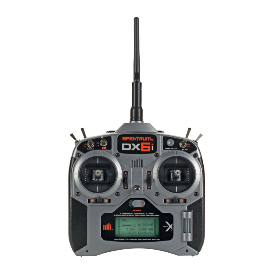
- Page 29 Antenna Handle Mix/Throttle Hold Trainer/Bind Flap/Gyro Throttle Cut Gear/Flight Mode Rudder Dual Rate Elevator Dual Rate Aileron Dual Rate Throttle/Rudder Stick Aileron/Elevator Stick Rudder Trim Elevator Trim Aileron Trim Throttle Trim Roller On/Off Switch The Throttle ALT function makes the throttle stick trim active only when the throttle stick is at less than half throttle. This allows accurate idle adjustments without affecting the mid to high throttle position.
- Page 30 When the battery voltage drop below 4.3 volts an alarm will sound and the screen will flash. The DX6i offers a Trainer function that allows the transmitter to operate as a master or slave. The trainer switch is located on the back left of the transmitter. (The trainer switch is located on the back right on Mode 1 transmitters.) MASTER The transmitter can be used as a master but the slave transmitter must have the same programming (i.e.
- Page 31 The SETUP list contains the programming functions that are normally only used during the initial setup of the model. (i.e. model type, servo reverse, model name). MODEL TYPE THRO CUT List RANGE CHECK List List POSITION - ACT CHECK ACRO HELI Throttle Cut (Page 41) Range Check (Page 50)
- Page 32 Press the ROLLER and hold while turning on the transmitter. When SETUP LIST appears on screen, release the roller. Reduce photo to 13.5% SETUP LIST Main MODEL TYPE Alternatively the setup list can be accessed from the main screen by pressing the roller to access the ADJUST LIST then scrolling through the ADJUST LIST by rolling the roller to highlight SETUP LIST;...
- Page 33 The DX6i features two programming types: Airplane and Helicopter. The DX6i can memorize data for up to 10 models individually and the model type will automatically be stored with each model memory. Press the ROLLER and hold while turning on the transmitter. When SETUP LIST appears on screen release the roller.
- Page 34 Rotate the roller to highlight the desired model type ACRO (airplane) or HELI helicopter then press the roller to program that model type in model memory. Note that when changing model type all programming from the previous model will be erased and the new model will be reset to factory default settings. Reduce photo to 13.5% MODEL TYPE List...
- Page 35 The Model Name function is used to input and assign the model’s name to a specific memory, allowing easy identification of each model’s program. Each model’s name is displayed on the main screen when that model is selected. Up to eight characters that include numbers and letters are available. Press the ROLLER and hold while turning on the transmitter.
- Page 36 Rotate the roller to highlight the block below the MODEL # shown on the screen then press the roller. Reduce photo to 13.5% MODEL NAME List MODEL MUSTANG Rotate the roller to select the desired position that you wish to assign a letter or number then press the roller to access the numbers or letter characters.
- Page 37 The servo monitor screen serves as a useful tool when programming your radio. It displays servo movement and direction when different programming functions, sticks and/or switches are moved. Press the ROLLER and hold while turning on the transmitter to enter the SETUP LIST. When SETUP LIST appears on screen release the roller.
- Page 38 Press the roller to access the Servo monitor screen. Reduce photo to 13.5% MONITOR List Press and hold the roller for more than 3 seconds then release the roller and the system will return to the main screen. Rotate the roller to highlight LIST in the upper right corner then pressing the roller will return the system to the SETUP LIST screen.
-
Page 39: Servo Reversing
The Reverse Switch function allows electronic means of reversing the servo’s throw. Servo reversing is available for all six channels. Press the ROLLER and hold while turning on the transmitter. When SETUP LIST appears on screen release the roller. Alternatively the setup list can be accessed from the main screen by pressing the roller to access the ADJUST LIST then scrolling through the ADJUST LIST by rolling the roller to highlight SETUP LIST then press the roller. - Page 40 Rotate the roller to highlight the desired channel then press the roller to select that channel. Reduce photo to 13.5% REVERSE List THRO-N AILE-N ELEV-N RUDD-N GEAR-N FLAP-N With the desired channel selected rotate the roller to select (N=Normal, R=Reverse). When the reverse direction is selected press the roller to deselect the channel.
- Page 41 The DX6i offers a Throttle Cut function. When the Throttle Cut button is pressed, the throttle moves to the low throttle, low trim position, allowing the safe and convenient shut down of the engine. Press the ROLLER and hold while turning on the transmitter. When SETUP LIST appears on screen release the roller.
- Page 42 Rotate the roller to highlight INH then press the roller to highlight INH. Now rotate the roller to ACT or INH the Throttle Cut function. Reduce photo to 13.5% THRO CUT List POSITION - ACT Press and hold the roller for more than 3 seconds then release the roller and the system will return to the main screen.
- Page 43 The DX6i offers three different wing types to choose from: Normal, Dual aileron and Elevon (also called Delta mixing). In addition, V-Tail mixing is available from this screen. When the DUALAILE and ELEVON wing function are INH, Normal wing type is selected. Use this wing type with common aircraft that utilize only one servo for both ailerons.
- Page 44 Rotate the roller to highlight WINGTAILMIX then press the roller to access the Wing tail mix function. Reduce photo to 13.5% SETUP LIST Main THRO CUT WINGTAILMIX D/R COMBI Rotate the roller to highlight the desired wing or tail type then press the roller to highlight the desired function. Rotate the roller to inhibit (INH) or activate (ACT) the function.
- Page 45 Dual Aileron Wing Type Connection AUX1 Servo Port AILE Servo Port (Left Aileron) (Right Aileron) V-Tail Type Connection ELEV Servo Port RUDD Servo Port (Left V-Tail) (Right V-Tail) Elevon Wing Type Connection AILE Servo Port ELEV Servo Port (Left Aileron) (Right Aileron) Press and hold the roller for more than 3 seconds then release the roller and the system will return to the main screen.
- Page 46 The Dual Rate Combi switch assignment function allows the aileron, elevator and rudder dual rate and exponential functions to be assigned to one of four common switches such that the dual rates/expos for all three channels can be accessed using a single switch. To access the dual rate combi function rotate the roller to highlight D/R COMBI then press the roller to access the Dual Rate Combi function.
- Page 47 Rotate the roller to highlight IHN then press the roller. Now rotate the roller to select AILE, ELEV, RUDD or GEAR. Reduce photo to 13.5% D/R COMBI List D/R SW: Press and hold the roller for more than 3 seconds then release the roller and the system will return to the main screen.
-
Page 48: Trainer
The DX6i features an on screen timer with two programming options: Down Timer - The countdown timer allows a preset time in ten-second intervals up to 59 minutes and 50 seconds to be programmed, and when that time expires, a beeper will sound five (5) beeps every five (5) seconds. -
Page 49: Setup List
Reduce photo to 13.5% SETUP LIST Main D/R COMBI TIMER RANGE CHECK Rotate the roller to highlight TIMER then press the roller to access the Timer function. Reduce photo to 13.5% TIMER List MDL6 MUSTANG DOWN TIMER-06:00 SWITCH---TRAINER Rotate the roller to highlight the desired timer function that you wish to change. UP/ Down- selects the up or down timer function TIME- in minutes or seconds Switch Options- Trainer or Throttle Cut... - Page 50 RANGE CHECK: When activated the Range Check screen allows for a range check by using the trainer switch to reduce the output power. Press the ROLLER and hold while turning on the transmitter. When SETUP LIST appears on screen release the roller.
- Page 51 Rotate the roller to highlight RANGE and press the roller to access the range function. Reduce photo to 13.5% RANGE CHECK List CHECK 1. With the model on and resting on the ground, stand 30 paces (approx. 90 feet) away from the model. 2.
- Page 52 The power setting screen is used to place the transmitter in one of two power settings. A-EU 328 is appropriate for most European countries conforming to EU 300-328, while B-US 247 should be selected for use in the United States and countries outsde the EU. Press the ROLLER and hold while turning on the transmitter.
- Page 53 The contrast function allows the adjustment of the screen contrast. Press the ROLLER and hold while turning on the transmitter. When SETUP LIST appears on screen release the roller. Alternatively the setup list can be accessed from the main screen by pressing the roller to access the ADJUST LIST, then scrolling through the ADJUST LIST by rolling the roller to highlight SETUP LIST, then pressing the roller.
- Page 54 CONTRAST: Allows the adjustment of the screen contrast from 0 to100%. Reduce photo to 13.5% CONTRAST List Rotate the roller to adjust the screen contrast from 0 to 100%. Press and hold the roller for more than 3 seconds then release the roller and the system will return to the main screen.
- Page 55 The COPY function allows the current model memory that is being used to be transferred to any of the other 9 available model memories. This is useful when experimenting with different model setups. The Model Reset function allows the model memory of the current model to be reset to the factory default setting. Press the ROLLER and hold while turning on the transmitter.
- Page 56 Rotate the roller to highlight COPY then press the roller to enter the COPY function. Rotate the roller to COPY and select the model memory that you wish to copy by pressing and rotating the roller. Reduce photo to 13.5% COPY/RESET List MODEL 6 MUSTANG...
- Page 57 Rotate the roller to highlight COPY/RESET then press the roller to access the COPY/RESET function. Reduce photo to 13.5% COPY/RESET List MODEL 6 MUSTANG COPY RESET Rotate the roller to highlight RESET then press the roller to enter the RESET function. Rotate the roller to YES, next to SURE, and then press the roller to reset the model to factory default settings.
- Page 58 The adjust list contains programming features that are commonly used to adjust flight characteristics. These functions included dual rate and expo, travel adjust, mixes, etc. The adjust list is accessible from the main screen by simply pressing the roller or is available through the SETUP LIST. MIX 1 MODEL SELECT List...
- Page 59 With the transmitter already powered on and the main screen displayed, press and release the ROLLER to enter the ADJUST LIST. Reduce photo to 13.5% ADJUST LIST Main MODEL SELECT Press and hold the roller for more than 3 seconds then release the roller and the system will return to the main screen.
-
Page 60: Model Name
The DX6i features a memory function that stores the programmed data for up to 10 models. Any combination of up to 10 airplanes and/or helicopters can be stored in memory. A model name feature with up to eight characters allows each model to be easily identified. (See page 35) With the transmitter already powered on and the main screen displayed, press and release the ROLLER to enter the ADJUST LIST. - Page 61 Turning the transmitter off then back on will also return to the main screen. The DX6i features patented ModelMatch™ technology that prevents operating a model using the wrong memory. This feature can prevent stripped servo gears, broken linkages and even a crash due to trying to operate/ fly a model using the wrong memory.
- Page 62 The Dual Rate and Exponential function allows two control rates to be programmed and selected with a switch. Dual rates and Expos are available on the aileron, elevator and rudder channels. Changing the dual rate value not only affects the maximum control authority but also affects the overall sensitivity of control. A higher rate yields a higher overall sensitivity.
- Page 63 Rotate the ROLLER to the right until D/R&EXPO is highlighted on screen. Reduce photo to 13.5% ADJUST LIST Main MODEL SELECT D/R&EXPO TRAVEL ADJ Press the roller to access the Dual Rate and Expo function. Reduce photo to 13.5% D/R&EXPO List AILE 1 100% INH%...
- Page 64 The Travel Adjust function allows the precise end-point adjustments of all six channels in each direction independently. The travel adjust range is from 0–125%. Channels available for programming are: With the transmitter already powered on and the main screen displayed, press and release the ROLLER to enter the ADJUST LIST.
- Page 65 Press the roller to access the TRAVEL ADJ function. Reduce photo to 13.5% TRAVEL ADJ List THRO+100% AILE+100% ELEV+100% RUDD+100% GEAR+100% FLAP+100% Move the respective stick or switch in the desired direction that you wish to change the travel adjust. Rotate the roller to highlight the desired channel’s value that you wish to adjust.
- Page 66 The Sub-Trim function allows you to electronically adjust the centering of each servo. Sub trim is individually adjustable for all six channels, with a range of + or - 100% (+ or - 30 degrees servo travel). Caution: Do not use excessive sub-trim values as it is possible to overdrive the servo’s maximum travel.
- Page 67 Press the roller to access the SUB TRIM function. Reduce photo to 13.5% SUB TRIM List THRO AILE ELEV RUDD GEAR FLAP Rotate the roller to highlight the desired channel’s value that you wish to adjust. Press the roller to access the sub trim value. Rotate the roller to adjust the sub trim value.
- Page 68 FLAP The Flap System allows the flap and elevator positions to be programmed for landing and takeoff. This is accomplished by selecting values for the elevator and flaps to be activated when the Flap/ Gyro is engaged. Two flap and elevator positions are available. Normal and Land. To access the FLAPS function Press the ROLLER and hold while turning on the transmitter.
- Page 69 Rotate the roller to highlight FLAPS and press the roller to access the FLAPS function. Reduce photo to 13.5% FLAPS List FLAP ELEV NORM+ LAND Rotate the roller to highlight the desired flap or elevator value that you wish to adjust then press the roller to access the selected value.
- Page 70 The DX6i offers two programmable mixes that allow stick or switch inputs to control the output of two or more servos. This function allows mixing any one channel to any other channel, or the ability to mix a channel to itself.
- Page 71 Press the roller to access the MIX 1 function. Reduce photo to 13.5% MIX 1 List THRO≥ THRO ACT RATE D 0% U SW ON TRIM INH Rotate the roller to highlight the master (left) channel in the screen. Reduce photo to 13.5% MIX 1 List THRO≥...
- Page 72 Rotate the roller to select the desired master channel. Press the roller to deselect the master channel then rotate the roller to select the slave channel. Press the roller to access the slave channel selection. Rotate the roller to select the desired slave channel. Rotate the roller to highlight the desired rate and direction.
- Page 73 The Mixes can be turned off and on using one of the following switches: Always on GEAR- Gear switch forward FLAP- Flap switch down AIL D/R- Aileron Dual Rate switch up ELE D/R- Elevator Dual Fate switch up MIX- Mix switch forward Rotate the roller to highlight SW.
- Page 74 Both mixes offer a trim feature that, when activated, cause the master channel’s trim to also affect the slave channel. Rotate the roller to highlight TRIM. Reduce photo to 13.5% MIX 1 List THRO≥ THRO ACT RATE D 0% U SW AIL D/R TRIM ACT Press the roller to access the trim function.
- Page 75 : Only available when Flaperon or Elevon is activated (see Wing Tail Mix Page 43). The Differential Aileron function allows precise electronic adjustments of the up vs. down aileron travel of both ailerons. Aileron differential is used to reduce unwanted yaw characteristics during roll inputs. In order to access the Differential Function, flaperon or elevon wing mixing must be selected and two servos must be used to operate the ailerons.
- Page 76 Press the roller to access the DIFFERENTIAL function. Reduce photo to 13.5% DIFFERENTIAL List DUALAILE RATE Rotate the roller to highlight the Differential value. Press the roller to access the Differential value. Rotate the roller to adjust the Differential value. After the desired value is programmed press the roller to deselect the value.
-
Page 77: Throttle Cut
Antenna Handle Mix/Throttle Hold Trainer/Bind Flap/Gyro Throttle Cut Gear/Flight Mode Rudder Dual Rate Elevator Dual Rate Aileron Dual Rate Throttle/Rudder Stick Aileron/Elevator Stick Rudder Trim Elevator Trim Aileron Trim Throttle Trim Roller On/Off Switch... - Page 78 When the battery voltage drops below 4.3 volts an alarm will sound and the voltage bar will flash. When the DX6i is operated in the helicopter mode, there is a warning system that is employed to avoid hot starts (accidental high throttle startups) when the power switch is initially turned ON. If the flight mode switch or throttle hold is on, an alarm will sound and a warning message will be displayed on the LCD.
-
Page 79: Timer
The SETUP list contains the programming functions that are normally only used during the initial setup of the model (i.e. model type, servo reverse, model name). SETUP LIST includes programming functions that are normally used during setup. System programming functions for helicopters include: MODEL TYPE SWASH TYPE... - Page 80 Press the ROLLER and hold while turning on the transmitter. When SETUP LIST appears on screen, release the roller. Reduce photo to 13.5% SETUP LIST Main MODEL TYPE Alternatively the setup list can be accessed from the main screen by pressing the roller to access the ADJUST LIST then scrolling through the ADJUST LIST by rolling the roller to highlight SETUP LIST, then press the roller and the SETUP LIST will appear.
- Page 81 The DX6i features two programming types: Airplane and Helicopter. The DX6i can memorize data for up to 10 models individually and the model type will automatically be stored with each model memory. Press the ROLLER and hold while turning on the transmitter. When SETUP LIST appears on screen, release the roller.
- Page 82 Rotate the roller to highlight the desired model type ACRO (airplane) or HELI helicopter then press the roller to program that model type in model memory. Note that when changing model type all programming from the previous model will be erased and the new model will be reset to factory default settings. Reduce photo to 13.5% MODEL TYPE List...
- Page 83 The Model Name function is used to input and assign the model’s name to a specific memory, allowing easy identification of each model’s program. Each model’s name is displayed on the main screen when that model is selected. Up to eight characters that include numbers and letters are available. Press the ROLLER and hold while turning on the transmitter.
- Page 84 Rotate the roller to highlight the block below the MODEL # shown on the screen then press the roller. Reduce photo to 13.5% MODEL NAME List MODEL BLADE 400 Rotate the roller to select the desired position that you wish to assign a letter or number to then press the roller to access the numbers or letter characters.
- Page 85 The servo monitor screen serves as a useful tool when programming your radio. It displays servo movement and direction when different programming functions, sticks and/or switches are moved. Press the ROLLER and hold while turning on the transmitter to enter the SETUP LIST. When SETUP LIST appears on screen release the roller.
- Page 86 Press the roller to access the Servo monitor screen. Reduce photo to 13.5% MONITOR List Press and hold the roller for more than 3 seconds then release the roller and the system will return to the main screen. Rotate the roller to highlight LIST in the upper right corner then pressing the roller will return the system to the SETUP LIST screen.
- Page 87 The Reverse Switch function provides an electronic means of reversing the servo throw. Servo reversing is available for all six channels. Press the ROLLER and hold while turning on the transmitter. When SETUP LIST appears on screen release the roller. Alternatively the setup list can be accessed from the main screen by pressing the roller to access the ADJUST LIST, then scrolling through the ADJUST LIST by rolling the roller to highlight SETUP LIST, then pressing the roller.
- Page 88 Rotate the roller to highlight the desired channel then press the roller to select that channel. Reduce photo to 13.5% REVERSE List THRO-N AILE-N ELEV-N RUDD-N GYRO-N PITC-N With the desired channel selected rotate the roller to select (N=Normal, R+Reverse). When the reverse direction is selected press the roller to deselect the channel.
- Page 89 The DX6i offers 2 swashplate types: One Servo: 90 degrees (standard mechanical mix) Three Servo: CCPM 120 degrees Select the swashplate type to match your helicopter. Press the ROLLER and hold while turning on the transmitter. When SETUP LIST appears on screen release the roller.
- Page 90 Rotate the roller to select 1 servo 90 degrees or CCPM 120 degrees swashplate mixing. Reduce photo to 13.5% SWASH TYPE List 1SERVO90° After the desired swashplate type is programmed press the roller to deselect the value. Press and hold the roller for more than 3 seconds then release the roller and the system will return to the main screen.
- Page 91 The DX6i offers a Throttle Cut function. When the Throttle Cut button is pressed, the throttle moves to a preprogrammed position (low throttle, low trim) allowing the safe and convenient shut down of the engine. Press the ROLLER and hold while turning on the transmitter. When SETUP LIST appears on screen release the roller.
- Page 92 Rotate the roller to highlight INH then press the roller to access INH. Now rotate the roller to ACT or INH the Throttle Cut function. Reduce photo to 13.5% THRO CUT List POSITION - ACT Press and hold the roller for more than 3 seconds then release the roller and the system will return to the main screen.
- Page 93 The Dual Rate Combi switch assignment function allows the aileron, elevator and rudder dual rate and exponential functions to be assigned to one of four common switches such that the dual rates/expos for all three channels can be accessed using a single switch. To access the Dual Rate Combi function rotate the roller to highlight D/R COMBI then press the roller to access the Dual Rate Combi function.
- Page 94 Rotate the roller to highlight IHN then press the roller. Now rotate the roller to select AILE, ELEV, RUDD or FM FLIGHT MODE. Reduce photo to 13.5% D/R COMBI List D/R SW: Press and hold the roller for more than 3 seconds then release the roller and the system will return to the main screen.
- Page 95 The DX6i features an on screen timer with two programming options: Down Timer - The countdown timer allows a preset time in ten-second intervals up to 59 minutes and 50 seconds to be programmed, and when that time expires, a beeper will sound five (5) beeps every five (5) seconds.
- Page 96 Alternatively the setup list can be accessed from the main screen by pressing the roller to access the ADJUST LIST then scrolling through the ADJUST LIST by rolling the roller to highlight SETUP LIST then press the roller. Reduce photo to 13.5% TIMER List MDL1 BLADE400...
-
Page 97: Power Setting
RANGE CHECK: When activated the range check screen allows for a range check by using the trainer switch to reduce the output power. Press the ROLLER and hold while turning on the transmitter. When SETUP LIST appears on screen release the roller. Alternatively the setup list can be accessed from the main screen by pressing the roller to access the ADJUST LIST, then scrolling through the ADJUST LIST by rolling the roller to highlight SETUP LIST then pressing the roller. - Page 98 Rotate the roller to highlight RANGE and press the roller to access the range function. Reduce photo to 13.5% RANGE CHECK List CHECK 1. With the model on and resting on the ground, stand 30 paces (approx. 90 feet) away from the model. 2.
-
Page 99: Contrast
The power setting screen is used to place the transmitter in one of two power settings. A-EU 328 is appropriate for most European countries conforming to EU 300-328, while B-US 247 should be selected for use in the United States and outside the EU. Press the ROLLER and hold while turning on the transmitter. -
Page 100: Copy/Reset
The contrast function allows the adjustment of the screen contrast. Rotate the roller to highlight CONTRAST then press the roller to access the contrast function. Alternatively the setup list can be accessed from the main screen by pressing the roller to access the ADJUST LIST, then scrolling through the ADJUST LIST by rolling the roller to highlight SETUP LIST, then pressing the roller. - Page 101 CONTRAST: Allows the adjustment of the screen contrast from 0 to100%. Reduce photo to 13.5% CONTRAST List Rotate the roller to adjust the screen contrast from 0 to 100%. Press and hold the roller for more than 3 seconds then release the roller and the system will return to the main screen.
-
Page 102: Adjust List
The COPY function allows the current model memory that is being used to be transferred to any of the other 9 available model memories. This is useful when experimenting with different model setups. The Model Reset function allows the model memory of the current model to be reset to the factory default setting. Press the ROLLER and hold while turning on the transmitter. - Page 103 Rotate the roller to highlight COPY then press the roller to enter the COPY function. Reduce photo to 13.5% COPY/RESET List MODEL 1 BLADE400 COPY RESET Rotate the roller to COPY and select the model memory that you wish to copy by pressing the roller then rotating the roller.
- Page 104 Rotate the roller to highlight COPY/RESET then press the roller to access the COPY/RESET function. Reduce photo to 13.5% COPY/RESET List MODEL 1 BLADE400 COPY RESET Rotate the roller to highlight RESET then press the roller to enter the RESET function. Reduce photo to 13.5% RESET List...
-
Page 105: Model Select
The adjust list contains programming features that are commonly used to adjust flight characteristics. These functions included Dual Rate and Expo, Travel Adjust, Pitch and Throttle Curves, Mixes, etc. The Adjust List is accessible from the main screen by simply pressing the roller or is available through the SETUP LIST. MODEL SELECT PITC CUR List... - Page 106 With the transmitter already powered on and the main screen displayed, press and release the ROLLER to enter the ADJUST LIST. Reduce photo to 13.5% ADJUST LIST Main MODEL SELECT Press and hold the roller for more than 3 seconds then release the roller and the system will return to the main screen.
- Page 107 The DX6i features a memory function that stores the programmed data for up to 10 models. Any combination of up to 10 airplanes and/or helicopters can be stored in memory. A model name feature with up to eight characters allows each model to be easily identified. (See Page 83) With the transmitter already powered on and the main screen displayed, press and release the ROLLER to enter the ADJUST LIST.
- Page 108 Turning the transmitter off then back on will also return to the main screen. ™ The DX6i features patented ModelMatch technology that prevents operating a model using the wrong memory. This feature can prevent stripped servo gears, broken linkages and even a crash due to trying to operate/ fly a model using the wrong memory.
-
Page 109: Dual Rate And Exponential
The Dual Rate and Exponential function allows two control rates to be programmed and selected with a switch. Dual rates and Expos are available on the aileron, elevator and rudder channels. Changing the dual rate value not only affects the maximum control authority but also affects the overall sensitivity of control. A higher rate yields a higher overall sensitivity. - Page 110 Rotate the ROLLER to the right until D/R&COMBI is highlighted on screen. Reduce photo to 13.5% ADJUST LIST Main MODEL SELECT D/R&EXPO TRAVEL ADJ Press the roller to access the Dual Rate and Expo function. Reduce photo to 13.5% D/R&EXPO List AILE 1 100% INH%...
-
Page 111: Travel Adjust
The Travel Adjust function allows the precise end-point adjustments of all six channels in each direction independently. The travel adjust range is from 0–125%. Channels available for programming are: With the transmitter already powered on and the main screen displayed, press and release the ROLLER to enter the ADJUST LIST. - Page 112 Press the roller to access the TRAVEL ADJ function. Reduce photo to 13.5% TRAVEL ADJ List THRO+100% AILE+100% ELEV+100% RUDD+100% GYRO+100% PITC+100% Move the respective stick or switch in the desired direction that you wish to change the travel adjust. Rotate the roller to highlight the desired channel’s value that you wish to adjust.
-
Page 113: Sub-Trim
The Sub-Trim function allows you to electronically adjust the centering of each servo. Sub trim is individually adjustable for all seven channels, with a range of + or - 100% (+ or - 30 degrees servo travel). Caution: Do not use excessive sub-trim values as it is possible to overdrive the servo’s maximum travel. - Page 114 Press the roller to access the SUB TRIM function. Reduce photo to 13.5% SUB TRIM List THRO AILE ELEV RUDD GYRO PITC Rotate the roller to highlight the desired channel’s value that you wish to adjust. Press the roller to access the sub trim value. Rotate the roller to adjust the sub trim value.
- Page 115 The gyro function offers two selectable gyro gain values that can be selected via the flight mode switch or the gyro switch. When active the Gyro’s gain channel is plugged into the gear channel/(channel 5). With the transmitter already powered on and the main screen displayed, press and release the ROLLER to enter the ADJUST LIST.
- Page 116 Press the roller to access the GYRO screen. Reduce photo to 13.5% GYRO List Rotating the roller Highlight INH then press the roller. Rotate the roller to ACT then press the roller to activate the GYRO function. Reduce photo to 13.5% GYRO List RATE...
- Page 117 If F.MODE is selected the option of choosing either rate that is assigned to NORM or STUNT modes is available. By assigning 0 or 1 to NORM or STUNT, the gain value is automatically selected whenever the Normal or Stunt flight mode is selected.
- Page 118 The DX6i offers two (2) separate throttle curves with five (5) adjustable points per curve. This function allows you to adjust the throttle curve to optimize engine rpm at a particular pitch setting. Once the throttle curves are established, each can be activated in flight using the 2-position flight mode switch. The flight mode switch offers two (2) selectable curves: 0=Normal, 1=Stunt.
- Page 119 Press the roller to access the Throttle Curve function. Reduce photo to 13.5% THRO CUR List NORM + POS 3 STUNT HOLD 50.0% Rotate the roller to highlight the desired throttle curve that you wish to adjust. NORM- Normal STUNT- Stunt mode HOLD- Hold...
- Page 120 Rotate the roller to adjust the throttle value at the select stick position. After the desired value is programmed press the roller to deselect the value. : In Throttle Hold the throttle curve is a flat line representing a hold condition. The Hold position can be adjusted using the values as above.
- Page 121 The DX6i offers three (3) independent pitch curves: Normal, Stunt 1, Hold. Each pitch curve contains five (5) adjustable points — L, 1, 2, 3 and H.
- Page 122 Press the roller to access the Pitch Curve function. Reduce photo to 13.5% PITC CUR List NORM + POS 3 STUNT HOLD 50.0% Rotate the roller to highlight the desired pitch curve that you wish to adjust. NORM- Normal STUNT- Stunt mode HOLD- Hold Press the roller to access the selected pitch curve.
- Page 123 The Swashplate Mix screen adjusts the amount and direction of travel for the aileron, elevator and pitch functions. For example, if more aileron travel is desired, increasing the aileron swashplate mix value will increase the overall travel of the servos necessary to achieve greater aileron throw. Defaults are set to +60%. : Negative swashplate values are available which will reverse the direction of that function.
- Page 124 Press the roller to access the Swashplate Mix function. Reduce photo to 13.5% SWASH MIX List AILE ELEV PITCH Rotate the roller to highlight the desired channel that you wish to adjust. AILE- Aileron ELEV- Elevator PITC- Pitch Press the roller to access the selected channel’s value. Rotate the roller to select adjust the selected value.
- Page 125 The DX6i offers two programmable mixes that allow stick or switch inputs to control the output of two or more servos. This function allows mixing any one channel to any other channel, or the ability to mix a channel to itself.
- Page 126 Press the roller to access the MIX 1 function. Reduce photo to 13.5% MIX 1 List THRO≥ THRO ACT RATE D 0% U SW ON TRIM INH Rotate the roller to highlight the master (left) channel in the screen. Reduce photo to 13.5% MIX 1 List THRO≥...
- Page 127 Press the roller to deselect the master channel then rotate the roller to select the slave channel. Press the roller to access the slave channel selection. Rotate the roller to select the desired slave channel. Rotate the roller to highlight the desired rate and direction. Reduce photo to 13.5% MIX 1 List...
- Page 128 The Mixes can be turned off and on using one of the following switches. Always on F MODE- F switch forward GYRO- Gyro switch down AIL D/R- Aileron dual rate switch up ELE D/R- Elevator dual rate switch up MIX- Mix switch forward Rotate the roller to highlight SW.
- Page 129 Both mixes offer a trim feature that, when activated, cause the master channel’s trim to affect the slave channel. Rotate the roller to highlight TRIM. Reduce photo to 13.5% MIX 1 List THRO≥ THRO ACT RATE D 0% U SW AIL D/R TRIM ACT Press the roller to access the trim function.
- Page 130 Because torque reaction varies with different power settings, it is necessary to vary the tail rotor pitch at the same time. The DX6i offers two (2) separate revolution mixing programs with independent up and down mixing for each—one for flight mode position 0, and the other for Stunt mode. The U, or Up, mixing adjusts the tail rotor compensation for the mid to high throttle/stick setting, and the D, or Down, mixing adjusts the tail rotor compensation for the mid to low throttle/stick setting.
- Page 131 Reduce photo to 13.5% REVO MIX List NORM+ STUNT 0% UP 0% DN Rotate the roller to highlight the desired value that you wish to adjust. Press the roller to access the selected value. Rotate the roller to select adjust the selected value. After the desired value is programmed press the roller to deselect the value.
-
Page 132: Fcc Information
FCC Information This device complies with part 15 of the FCC rules. Operation is subject to the following two conditions: (1) This device may not cause harmful interference, and (2) this device must accept any interference received, including interference that may cause undesired operation. Caution: Changes or modifications not expressly approved by the party responsible for compliance could void the user’s authority to operate the equipment. -
Page 133: General Notes
General Notes Radio controlled models are a great source of pleasure. Unfortunately, they can also pose a potential hazard if not operated and maintained properly. It is imperative to install your radio control system correctly. Additionally, your level of piloting competency must be high enough to ensure that you are able to control your aircraft under all conditions. - Page 134 Federal Aviation Administration Purpose This advisory outlines safety standards for operations of model aircraft. We encourage voluntary compliance with these standards. Background Attention has been drawn to the increase in model aircraft operation. There is a need for added caution when operating free flight and radio controlled craft in order to avoid creating a noise nuisance or a potential hazard to full-scale aircraft and persons and/or property on the surface.
-
Page 135: Range Check
Daily Flight Checks 1. Check the battery voltage on both the transmitter and the receiver battery packs. Do not fly below 4.3V on the transmitter or below 4.7V on the receiver. To do so can crash your aircraft. : When you check these batteries, ensure that you have the polarities correct on your expanded scale voltmeter. - Page 136 HORIZON SHALL NOT BE LIABLE FOR SPECIAL, INDIRECT OR CONSEQUENTIAL DAMAGES, LOSS OF PROFITS OR PRODUCTION OR COMMERCIAL LOSS IN ANY WAY CONNECTED WITH THE PRODUCT, WHETHER SUCH CLAIM IS BASED IN CONTRACT, WARRANTY, NEGLIGENCE, OR STRICT LIABILITY. Further, in no event shall the liability of Horizon exceed the individual price of the Product on which liability is asserted. As Horizon has no control over use, setup, final assembly, modification or misuse, no liability shall be assumed nor accepted for any resulting damage or injury.
-
Page 137: Inspection Or Repairs
verifying the proof-of- purchase date. Provided warranty conditions have been met, your Product will be repaired or replaced free of charge. Repair or replacement decisions are at the sole discretion of Horizon Hobby. Should your repair not be covered by warranty the repair will be completed and payment will be required without notification or estimate of the expense unless the expense exceeds 50% of the retail purchase cost. - Page 140 Champaign, Illinois 61822 (877) 504-0233 www.horizonhobby.com www.spektrumrc.com © 2007 DSM and DSM2 are trademarks or registered trademarks of Horizon Hobby, Inc. Spektrum is used with permission of Bachmann Industries, Inc. 11335.1 Spektrum radios and accessories are exclusively available from Horizon Hobby, Inc.
Need help?
Do you have a question about the DX6i and is the answer not in the manual?
Questions and answers