Table of Contents
Advertisement
Quick Links
Advertisement
Table of Contents
Troubleshooting

Subscribe to Our Youtube Channel
Summary of Contents for Yellowtec Digital Voice Processor
- Page 1 Manual 4.0 VIPdigital Manual 4.0 Yellowtec 2004 Rev. 26.07.2004 Page 1...
-
Page 2: Table Of Contents
TABLE OF CONTENTS BRIEF DESCRIPTION..................6 PRIOR TO BEGINNING ..................7 ..............7 ONVENTIONS USED IN THE MANUAL 2.1.1 Using the screen........................7 2.1.2 Printout ..........................7 ......................8 NPACKING ................... 8 COPE OF DELIVERY ..................9 AFETY INSTRUCTIONS GETTING STARTED WITH VIPDIGITAL............10 .................. - Page 3 4.3.2.2 Analog Left Out and Right Out....................18 4.3.2.3 Analog Hybrid-Out ........................18 4.3.2.4 Digital AES/EBU-Sync/In ......................18 4.3.2.5 Digital AES/EBU-Out ......................... 18 4.3.3 Remote Control ........................19 4.3.3.1 Remote Control D-Sub ......................19 4.3.3.2 Control-Out/In ..........................19 4.3.3.3 Technical data Control-Out/In (GPO/GPI) ................. 19 SOFTWARE INSTALLATION ................
- Page 4 ................31 INDOW ENERAL PTIONS 7.9.1 Range: Synchronization ...................... 31 7.9.1.1 Field: Frequency ........................31 7.9.1.2 Field: Sync Source........................31 7.9.2 Range: Access Internal Preset.................... 32 7.9.3 Range: Preset Order ......................32 7.9.4 Range: Replace Internal Preset ..................32 7.9.5 Range: Read SmartCard.....................
- Page 5 8.3.3 Saving and loading presets ....................55 8.3.3.1 Saving to PC..........................55 8.3.3.2 Loading from the PC........................56 8.3.3.3 Saving to VIPdigital........................57 8.3.3.4 Saving to SmartCard ......................... 57 8.3.3.5 Loading from VIPdigital......................58 8.3.4 Setting SmartCard presets ....................58 TECHNICAL DRAWINGS/DESCRIPTIONS .............
-
Page 6: Brief Description
1 BRIEF DESCRIPTION VIPdigital is a powerful digital voice processor. Its advanced Sharc DSP technology and its algorithms especially optimized for speech give you more power than any other mic processor you’ve encountered. It lets you tailor your talent’s voice with an unprecedented arsenal of processing tools, then mates it perfectly with your station’s on-air audio... -
Page 7: Prior To Beginning
2 PRIOR TO BEGINNING 2.1 Conventions used in the manual 2.1.1 Using the screen This manual was prepared, using Adobe Acrobat. To be able to use this manual, you must have Acrobat Reader 5.x or higher installed on your computer. Acrobat Reader is contained on the supplied CD-ROM. Follow the installation instructions from Adobe to install the Acrobat Reader. -
Page 8: Unpacking
2.2 Unpacking VIPdigital is delivered in a carton. Unpack the carton carefully. Remember the environment and dispose of the parts of foamed material and the cartons separately. 2.3 Scope of delivery The VIPdigital scope of delivery includes: 1. VIPdigital, 19“/1HU unit 2. -
Page 9: Safety Instructions
2.4 Safety instructions 1. Before installation or operation of equipment read all safety instructions warnings and operating instructions. 2. Heed all warnings on the equipment. 3. Follow the operating instructions. 4. The equipment may only be used for the purpose described in the operation instructions. 5. -
Page 10: Getting Started With Vipdigital
3 Getting started with VIPdigital 3.1 Electrical connection Connect VIPdigital to your local power supply. VIPdigital is equipped with a switched-mode power supply unit and can be operated on 90 to 240 V AC without any transfer. Always follow the local safety regulations! Also, read the safety information below! 3.2 Activation Switch on the power supply of the unit, using the power switch on the back panel. -
Page 11: The Enter Button
Once the SmartCard has been removed, the LED of the preset loaded last will blink again to indicate a new access to the internal preset. At this time, the preset loaded last by the SmartCard will be active. Press one of the three buttons to load an internal preset. Note: Use the VIPcon configuration software to configure VIPdigital for an alternative option of... -
Page 12: Unit Description
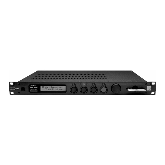
4 UNIT DESCRIPTION 4.1 Front panel 4.1.1 Remote Control RJ12 (1) This socket is a serial RS232 interface in the RJ12 connector format which can alternately be used for the RS232 interface on the back panel. It is offered to connect a VIPdigital installed in the rack to your PC. -
Page 13: Function Display (3)
4.1.3 Function Display (3) This display is designed to show the active preset as well as the different menu options in the Enter Mode. If one of the internal presets is active, the upper line of the display will show Internal Preset followed by its number and the lower line will show its name. -
Page 14: Enter (5)
4.1.5 Enter (5) The Enter button activates the Enter Mode for configuring different processor functions independently of the presets. Pressing the button causes the display to show select ACTION in its upper line and ESCAPE below it. At the same time, the LED of the Enter button will blink. -
Page 15: The Enter Mode
4.2 The Enter Mode Optionally, the Enter mode is activated with the green Enter key or by pressing the rotary Selector button arranged on its rights side. In this mode different processor functions which are independent of the preset selection may be configured and can be accessed via a menu system (see below). Pressing the button causes the display to show select ACTION in its upper line and... -
Page 16: State
4.2.3 State This menu item is exclusively designed to display the valid scan rate (44.1 or 48 kHz). Entries are not possible here. Proceed as follows: 1) Press the green Enter button or the Selector button to change to the Enter mode. The display shows the select ACTION message and... -
Page 17: Back Panel
4.3 Back panel 4.3.1 Power supply On the left side of the back panel there is an inlet connector for non-heating apparatus for the power supply and a power switch. Connect your VIPdigital to your local power supply. The unit is equipped with a switched-mode power supply and can be operated on 90-240V AC 50-60Hz without any transfer. -
Page 18: Analog Left Out And Right Out
4.3.2.2 Analog Left Out and Right Out (Con 5 / Con 6) These two electronically balanced analog outputs in the XLR format provide the stereo-output signals of the processor at line level. The reference of the analog outputs can be set using the Output Levels control within the VIPcon configuration software. -
Page 19: Remote Control
4.3.3 Remote Control 4.3.3.1 Remote Control D-Sub (Con 1) This serial interface is a 9-pin D-sub connector (DB9). This socket can alternately be used for the Remote Control RJ-12 connector on the front panel. Use this port for connecting your Windows PC. Refer to the Connection to the computer for details. -
Page 20: Software Installation
5 SOFTWARE INSTALLATION For the installation of the software package for VIPdigital a PC running Windows 95 or higher is required. We recommend to delete or relocate short cuts which belong to the older version(s) of the VIPdigital software. This can avoid the unintentional use of an older program version instead of the current version. -
Page 21: Connect Vipdigital To The Computer
6 CONNECT VIPdigital TO THE COMPUTER 6.1 Installing the connection To use the two VIPcon and VIPremote applications included in the VIPdigital scope of delivery, a serial connection must be established between your VIPdigital and your PC. To establish a connection to your PC, use a standard serial cable (in the scope of delivery). Connect a free serial port on your PC to the RS232 socket on the back panel of the unit. -
Page 22: Troubleshooting
6.3 Troubleshooting If VIPremote or VIPcon cannot connect to your VIPdigital, the following window appears: Note 1: Text may differ depending on your PC operating system Note 2: When you now prompt the “YES” button, the application you started will open in off-line mode Click “NO”... -
Page 23: Assigning Com Ports
6.4 Assigning COM Ports If your VIPdigital is connected to a higher port number than COM4, or if you want your VIP application to connect to a dedicated COM port, perform the following steps: (# stands for any COM port number available on your PC) Exit VIPremote/VIPcon In Windows Explorer, open the VIP program folder Create a short-cut of VIPremote.exe and/or VIPcon.exe... -
Page 24: Vipcon - The Configuration Software
7 VIPcon - THE CONFIGURATION SOFTWARE This chapter gives you a detailed description of the functional range of VIPcon. At this point we assume you have performed the software installation (Chapter SOFTWARE INSTALLATION) you have connected your VIPdigital to your PC (Chapter CONNECT VIPdigital TO THE COMPUTER 7.1 Start and end of program... -
Page 25: Online Operation
7.3 Online operation At this point we assume, that a data link in between your PC and your VIPdigital is established and working. If not, or if you have any further questions concerning this subject, please go back to Chapter CONNECT VIPdigital to your COMPUTER. -
Page 26: Menu: File
7.5 Menu: File 7.5.1 Sub-menu: New To create a new configuration file, select New. If a configuration has already been opened, this will be closed by the program. When creating a new configuration you will find standard entries which can then be modified according to your requirements. -
Page 27: Sub-Menu: Change Password
7.5.5 Sub-menu: Change Password VIPcon provides password protection. During each start of the program you will be prompted to enter a password. Note: The password is in the state of delivery. Use the Change Password dialogue to change the password. Once you have entered your new password, you must acknowledge it by a repeated entry. -
Page 28: Menu: Unit
7.6 Menu: Unit Note: The functions in this menu refer to the data exchange between VIPdigital and your PC. If the configuration software could not find a connection to a VIPdigital during the start, these functions will not be available and the menu shows gray color. If required, establish a connection between VIPdigital and the PC and restart the configuration software (the serial ports of your PC are only scanned during the start of the software). -
Page 29: Menu: Firmware Update
7.7 Menu: Firmware Update This option allows a replacement of the operating software (firmware) of VIPdigital by a more current version. Note 1: The function in this menu refers to the data exchange between VIPdigital and the PC. If the configuration software could not find a connection to VIPdigital during the start, these functions will not be available and the menu will show gray color. -
Page 30: Menu: Help
Note: A transmission of unsuitable or faulty data or interruptions during the data transmission to the base unit may corrupt the function of VIPdigital permanently. In this case the unit can only be commissioned by the manufacturer. Enter the file name (see below) of the new firmware to be transferred into the text line, e.g. -
Page 31: Window: General Options
7.9 Window: General Options 7.9.1 Range: Synchronization Set the internal clock frequency of VIPdigital here. Note 1: VIPdigital has a Sample Rate Converter (SRC) on the digital input. Note 2: An external (house) clock can also be used for a synchronization. 7.9.1.1 Field: Frequency 48 kHz: pre-selects 48 kHz for the internal clock oscillator 44,1 kHz: pre-selects 44,1 kHz for the internal clock oscillator... -
Page 32: Range: Access Internal Preset
7.9.2 Range: Access Internal Preset VIPdigital stores 100 Internal Presets. 3 of these presets are enabled for a direct selection via the Preset Recall buttons. As a default preset no. 1/2/3 refer to the buttons 1/2/3. Define here whether the assignment of the 3 enabled presets can be modified on VIPdigital (offline, without PC). -
Page 33: Range: Read Smartcard
7.9.5 Range: Read SmartCard Select among the 3 SmartCard Read options: Soft Read Enable When your SmartCard is inserted, VIPdigital will not accept a preset until one of the Preset Recall buttons is pressed. Radical Read Enable When the SmartCard is inserted, VIPdigital will accept the preset immediately. The preset number (1, 2 or 3) active prior to insertion will be accepted. -
Page 34: Range: Input Levels
7.9.9 Range: Input Levels Adapt the VIPdigital audio input levels to your studio environment here. “0dB“ identifies the internal reference level of VIPdigital which relates to the reference mark of the level tendency meter on the frontpanel of the unit. Your setting should relate to the reference level of the incoming signal. -
Page 35: Window: Control Logic
7.10 Window: Control Logic 7.10.1 Range: Trigger Outputs VIPdigital provides 4 trigger outputs (GPOs). These trigger outputs allow a transmission of commands to other units or to select signal lamps, relays, opto-couplers, etc. Select one of the functions available in theTrigger pulldown menu for each output. -
Page 36: Trigger Output Functions
7.10.1.1 Trigger Output Functions List of the functions in the Trigger pulldown menu: Disable No function on this output Button 1 Activates the trigger output when Preset 1 is selected Button 2 Activates the trigger output when Preset 2 is selected Button 3 Activates the trigger output when Preset 3 is selected Button E... -
Page 37: Range: Trigger Inputs
7.10.3 Range: Trigger Inputs VIPdigital provides 4 trigger inputs (GPIs). The trigger inputs allow commands from other units to be received to initiate actions and/or functions in VIPdigital. Thus, functions of your VIPdigital can be “controlled remotely”. Select a function available in the Action pulldown menu for each input. A number of logic combinations with external applications results. -
Page 38: Vipremote - The Remote Software
8 VIPremote - THE REMOTE SOFTWARE This chapter gives you a detailed description of the functional range of VIPremote. At this point we assume you have performed the software installation (Chapter SOFTWARE INSTALLATION) you have connected your VIPdigital to your PC (Chapter CONNECT VIPdigital TO THE COMPUTER) -
Page 39: Start And End Of Program
8.1.1 Start and end of program Start VIPremote via the Windows Start Menu program entries. If you wish VIPcon to be started via the Windows Explorer: the name of the program file is “VIPremote.EXE“ (the default installation path is C:\Program files\Yellowtec\VIPdigital …). Note: In Offline mode VIPremote and VIPcon can be active at the same time. -
Page 40: Start-Up Mode
8.1.4 Start-Up Mode new in version 4.0! The left-hand area contains elements for the preset administration. The preset lists are “empty”, i.e. settings and designations are neutral. The buttons in the lower section of the program window are designed to transmit presets between the PC and the processor and save or load presets to the hard disk of your PC. -
Page 41: Help Call
VIP Remote Software x.xx (the first three digits with a period behind the first digit are important). VIP digital Software x.xx (firmware in VIPdigital 19” unit) is only displayed if a unit is connected; otherwise, the display shows 0.00 or the last value. -
Page 42: Audio Processing Module
8.2 Audio Processing Module 8.2.1 Basic information VIPdigital provides 14 audio processing modules for processing your audio signals. The sequence of the individual modules represents the signal path from the input on the left upper corner to the Limiter module in the bottom line. Use the shift hand symbol to click once on the orange lettered bar of a module... -
Page 43: Module: Input
8.2.2 Module: Input 8.2.2.1 Input source Use the four buttons on the left side to select the desired input source. MIC1 Analog input 1 MIC2 Analog input 2 DIG. L AES/EBU input, left signal DIG. R AES/EBU input, right signal 8.2.2.2 Input Gain The pre-amplification of the selected input is set, using the two ANALOG GAIN and DIGITAL GAIN controllers. -
Page 44: Phantom Power
8.2.2.3 Phantom Power To supply a connected condenser microphone, Phantom Power (48V) can be applied to both analog inputs. To do so, click on the Phantom Power button. Note: Before activating the 48V Phantom Power, check whether the connected microphone is designed for this mode. -
Page 45: Module: De-Esser
8.2.5 Module: De-esser Application: Suppression of noisy hissing sounds. The De-esser is a compressor especially configured for a reduction of “S”- or sibilant sounds. This compressor operates on frequency selections. This means that only certain parts of the frequency spectrum initiate control activities in the input signal and the other signal components pass the module unchanged. -
Page 46: Module: Equalizer
8.2.6 Module: Equalizer (four identical modules independent of each other) VIPdigital provides four completely parametric equalizer modules which can be set and be arranged in the signal path independently of each other. The modules numbered EQ 1… EQ 4 have identical parameters and can thus be used within the entire audio spectrum. -
Page 47: Module: Expander
8.2.7 Module: Expander In practice, expanders are mostly used for suppressing interferences (background noise, tape noise) in modulation pauses. Signals whose level is higher than the value set with Threshold are not influenced. These are the signal portions you want to keep. If the signal level is below the Threshold value, it will be attenuated. -
Page 48: Module: Agc
8.2.8 Module: AGC AGC (Automatic Gain Control) is designed for an automatic and subtle gain readjustment if the signal level varies. As opposed to the compressor which responds quickly to short-term level modifications, the AGC will only become active if the signal level is above or below the set target level over an extended time. The use of AGC can be of great benefit for many applications, but always make sure to exactly know the functionality and carefully set the parameters. -
Page 49: Module: Compressor
8.2.9 Module: Compressor Application: The Compressor is one of the most important tools to give audio signals more loudness, especially with regard to voice processing for broadcast applications. The Compressor reduces the dynamic range within the upper level range. Signal peaks will be reduced. -
Page 50: Module: Delay
8.2.10 Module: Delay The Delay module inserts an adjustable signal delay into the signal path. As opposed to numerous digital effect processors, the delay is not used for a “sound” processing, but exclusively as a technically oriented tool for a compensation of delay times – such as for picture-related audio post-processing for a synchronization to the picture. -
Page 51: Module: Reverb
8.2.11 Module: Reverb The VIPdigital Reverb module allows the application of room simulations to the speaker signal. The effects which can be implemented by this module, for example, can be used for the production of jingles or in post-production to position the speaker in different acoustic environments. Or just enhance the sound by adding a minimal amount of this effect. -
Page 52: Module: Limiter
8.2.12 Module: Limiter A high quality, straight forward limiter rounds off the range of VIPdigital sound processing modules. The classical “brickwall” type provides perfect protection against overmodulation by just setting the Limiter Level. The advanced VIP software algrithms stand for a maximum of sound quality. Basic “attack-“... -
Page 53: Preset Management
8.3 Preset management 8.3.1 Overview VIPremote application window Display of the selected „active“ List of the 100 internal presets preset and text entry line SmartCard Presets Load and save VIPdigital Manual 4.0 Yellowtec 2004 Rev. 26.07.2004 Page 53... -
Page 54: Setting Presets
8.3.2 Setting presets After a restart of VIPremote start-up mode is active (refer to Start-Up Mode. An “empty” Internal Preset list is displayed (neutral names and values). Use the bar on the right side of the list to scroll through all positions, or use the +/- buttons. -
Page 55: Saving And Loading Presets
8.3.3 Saving and loading presets VIPdigital presets can be saved in 3 different formats on your PC: *.VIP Internal preset file VIPdigital Presets (100 presets) *.VSM SmartCard preset file SmartCard Presets (3 presets and holder name) *.VPR Single preset file Single Preset (currently selected preset) In former versions only the *.VIP format was available. -
Page 56: Loading From The Pc
8.3.3.2 Loading from the PC In case you intend to load a single preset file, first (in the VIPremote application window) select the preset, that shall be substituted. It may be one of the Internal Preset List or one of the SmartCard Presets. -
Page 57: Saving To Vipdigital
8.3.3.3 Saving to VIPdigital Click on the SAVE TO VIP button. All presets from the Internal Preset list are transferred to the processor. The transfer to VIPdigital will take some time, the progress is displayed by a red bar in the upper window section. Do not interrupt this process. -
Page 58: Loading From Vipdigital
8.3.3.5 Loading from VIPdigital Click on the LOAD FROM VIP button. The presets stored in VIPdigital are transferred to the VIPremote software on the PC. The transfer takes some time, and the progress is displayed by a red bar in the upper window section. The presets appear in the Internal Presets list in VIPremote. -
Page 59: Technical Drawings/Descriptions
9 TECHNICAL DRAWINGS/DESCRIPTIONS 9.1 Technical Data Analog Inputs (Two XLR Inputs) Selection of Input 1 or Input 2 by software toggle, 24-bit A/D, Software Configurable as 2x MIC or 2x adjustable Gain 0 to 54 dB (before A/D converter), Input LINE or 1x LINE + 1x MIC Impedance >6 k ohms (balanced, transformerless), 48V phantom power On/Off software switch selectable... -
Page 60: Block Diagram
Yellowtec VIPdigital Input Select Analog Gain Phantom Power ANALOG INPUT 1 AES/ Digital Gain AES/EBU digital Out Left/Right 24 Bit ANALOG INPUT 2 AUDIO Analog Left Out PROCESSING MODULES 24 Bit Analog Right Out AES/ DIGITAL INPUT INPUT MODULE AES/EBU - SYNC Analog Hybrid Out External Sync. -
Page 61: Pin Out Table
9.3 Pin Out Table Frontpanel RJ12 RS232 PC-Link Backplane Con 1 RS 232 Con 3 ANALOG-IN 1 Signal IN + In 1 / XLR3fem IN - Chassis Con 4 ANALOG-IN 2 PC-Link IN + In 2 / XLR3fem IN - Chassis Chassis Con 5... -
Page 62: Gpi/Gpo Circuit Examples
Examples for Examples for GPO - Connections GPI - Connections IMPORTANT opt. Schutzdiode 1. Relays 1. Switches/Relays Before using the control ports specified in this drawing, read the associated chapters in the user manual. from GPO 5V/12V/24V to GPI Improper use may lead to damage of your VIPdigital and/or the equipment connected to the GPIs/GPOs. -
Page 63: Updating Vipdigital To 4.0
10 UPDATING VIPdigital to 4.0 10.1 Prior to beginning If there is a previous version of the VIPdigital Software installed on your PC, please perform the following steps before updating the software: Save your configuration files (*.DVP) and your preset files in (a) separate folder(s) Delete or relocate short cuts which belong to the older version(s) of the VIPdigital software If there are configurations or presets stored in your VIPdigital which have not yet been saved as files on your PC, you should do this now, prior to the update! - Page 64 9. The following warning window appears on the PC screen: Note: A transmission of unsuitable or faulty data or interruptions during the data transmission to the base unit may corrupt the function of VIPdigital permanently. In this case the unit can only be commissioned by the manufacturer.
-
Page 65: Updating Preset Files
10.5 Updating Preset Files When loading preset data from the previous version into VIPremote 4.0 a warning window appears (see on the right). Click OK. The existing presets are assigned to numbers 1- 50. Another 50 presets with default names and values are appended with numbers 51-100. -
Page 66: Compatibility
10.7 Compatibility 10.7.1 Configuration files VIPcon configuration files of the previous version are basically compatible to the current version. But always check the settings of functions or values, that were not available in the previous version. In doubt you should create a new configuration based on the default values after VIPcon start-up. 10.7.2 Preset files Preset files of version 3.0 have to be converted to the current version. -
Page 67: Troubleshooting
11 TROUBLESHOOTING This chapter will be updated as required. Please note the information on our website http://www.yellowtec.com/ If malfunctions are detected on your unit, please check the version numbers of the software and firmware first. The remote software, the configuration software and the firmware must be suited to each other. -
Page 68: Miscellaneous
12 MISCELLANEOUS 12.1 Warranty Limited Warranty Duration The duration of limited warranty for YELLOWTEC VIPdigital is one year according to the terms and conditions of warranty of the manufacturer (see Notice Of Warranty). Notice of Warranty The terms and conditions of the Warranty applying to the Product accompanying this Notice of Warranty are found exclusively in the Notice of Warranty. -
Page 69: Ce Conformity Declaration
12.2 CE conformity declaration EU Declaration of Conformity (EN 61000) Product Audio equipment for digital and analog signals (Voice Processor) Product name YELLOWTEC VIPdigital Manufacturer THUM + MAHR GmbH Heinrich-Hertz Str. 1-3 D-40789 Monheim am Rhein Germany Safety EN 60950 Basic standard EN 50081 –...
Need help?
Do you have a question about the Digital Voice Processor and is the answer not in the manual?
Questions and answers