Table of Contents
Advertisement
Copyright
All rights are reserved. No part of this publication may be reproduced, transmitted, transcribed, stored in
a retrieval system or translated into any language or computer language, in any form or by any means,
electronic, mechanical, magnetic, optical, chemical, manual or otherwise, without the prior written
permission of the company. Brands and product names are trademarks or registered trademarks of their
respective companies.
The vendor makes no representations or warranties with respect to the contents herein and especially
disclaim any implied warranties of merchantability or fitness for any purpose. Further the vendor
reserves the right to revise this publication and to make changes to the contents herein without
obligation to notify any party beforehand. Duplication of this publication, in part or in whole, is not
allowed without first obtaining the vendor's approval in writing.
Trademark
All the trademarks or brands in this document are registered by their respective owner.
Disclaimer
We make no warranty of any kind with regard to the content of this user's manual. The content is subject
to change without notice and we will not be responsible for any mistakes found in this user's manual. All
the brand and product names are trademarks of their respective companies.
FCC Compliance Statement
This equipment has been tested and found to comply with the limits of a Class B digital device, pursuant
to Part 15 of the FCC Rules. These limits are designed to provide reasonable protection against harmful
interference in a residential installation. This equipment generates uses and can radiate radio frequency
energy and, if not installed and used in accordance with the instructions, may cause harmful interference
to radio communications. Operation of this equipment in a residential area is likely to cause harmful
interference in which case the user will be required to correct the interference at his own expense.
However, there is no guarantee that interference will not occur in a particular installation.
CE Mark
The device is in accordance with 89/336 ECC-ENC Directive.
P4M800 Pro
Advertisement
Table of Contents

Related Manuals for Albatron P4M800 Pro


Summary of Contents for Albatron P4M800 Pro
- Page 1 P4M800 Pro Copyright All rights are reserved. No part of this publication may be reproduced, transmitted, transcribed, stored in a retrieval system or translated into any language or computer language, in any form or by any means, electronic, mechanical, magnetic, optical, chemical, manual or otherwise, without the prior written permission of the company.
-
Page 2: User Manual
P4M800 Pro ® P4M800 Pro & VT8237R+ ® ® Support Socket 775 Intel Pentium 4/ Celeron D Processor User Manual To enable the Hyper-Threading (HT) Technology, your computer system is required to have the following components: ® ® CPU: An Intel... -
Page 3: Packing List
Unplug the AC power when you install or remove any device on the mainboard. Packing List P4M800 Pro mainboard FDD Cable HDD Cable P4M800 Pro Uer Manual CD P4M800 Pro Setup Driver CD I/O Bracket (for ATX case) USB 2.0 Cable (Optional) SATA Cable (Optional) SPDIF Out Cable (Optional) -
Page 4: Table Of Contents
Table of Contents CHAPTER 1. GETTING STARTED ..............1 ....................... 1 NTRODUCTION ....................... 2 PECIFICATION ....................5 ONFIGURATION Layout of P4M800 Pro ..................5 ................... 6 ARDWARE NSTALLATION CPU Processor Installation................6 Memory Installation: DDRII1/2 ..............7 Back Panel Configuration................9 Connectors..................... 10 Front Panel Headers: SW/LED, PWRLED, SPEAKER........ -
Page 5: Chapter 1. Getting Started
Channel Audio Effect) (See Appendix I). The mainboard also supports the Sony/Philips Digital Interfaces (SPDIF) function (optional). The P4M800 Pro comes with an onboard 10/100 Mbps Ethernet LAN chip. There is a LAN port on the back panel that you can directly plug an internet cable into. -
Page 6: Specification
4/ Celeron D Processor Support Hyper-Threading Technology Support 800/ 533 MHz FSB (Front Side Bus) frequencies Chipset: Northbridge Chipset – VIA® P4M800 Pro Southbridge Chipset – VIA® VT8237R+ I/O Controller – ITE® IT8712F-S AC’ 97 Aduio Codec – VIA® VT1616 LAN PHY –... -
Page 7: Shadow Ram
High performance Codec with high S/N ratio (>90 db) Support 6-channel playback capability (Super 5.1 Channel Audio Effect) Support Sony/ Philips Digital Interfaces (S/PDIF) function (Optional) Onboard LAN PHY: 10/100 Mbps Ethernet LAN supported I/O facilities: Support one VGA port for D-SUB Support PS/2 mouse and PS/2 keyboard Support 360 KB/720 KB/1.2 MB/1.44 MB/2.88 MB floppy disk drive Four onboard USB 2.0/ 1.1 ports... -
Page 8: Watch Dog Timer
This function is for detecting the system when it is unable to handle over-clocking configurations during the POST stage. Once the problem is detected, the system will reset the configurations and reboot the system within five seconds. ABS (Albatron BIOS Security): Supports ABS card (optional) Supports BIOS backup... -
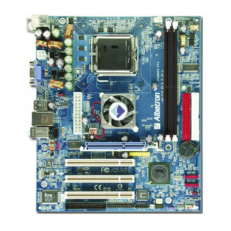
Page 9: Configuration
Configuration Layout of P4M800 Pro... -
Page 10: Hardware Installation
Hardware Installation This section will assist you in quickly installing your system hardware. Wear a wrist ground strap before handling components. Electrostatic discharge may damage the system’s components. CPU Processor Installation ® ® ® This mainboard supports Intel Pentium 4/ Celeron D processor using a Socket 775. -
Page 11: Memory Installation: Ddrii1/2
FAN Headers: CPUFAN, AUXFAN, CHASFAN Three power headers for cooling fans are available on the P4M800 Pro. The cooling fans play a very important role in maintaining CPU and ambient temperatures in your system. Please attach the fan power cords to these three headers. - Page 12 Memory Setup Steps: 1. Pull the white plastic tabs at both ends of the socket away. 2. Align a memory on the socket such that the notch on the memory matches the break on the socket. 3. Lower the memory vertically into the socket and press firmly by using both thumbs until the memory snaps into place.
-
Page 13: Back Panel Configuration
Back Panel Configuration PS/2 Mouse & PS/2 Keyboard Ports: KB/MS This mainboard provides a standard PS/2 mouse port and a PS/2 keyboard port. The pin assignments are described below. PS/2 Mouse Assignment Assignment Data +5 V (fused) Clock Ground PS/2 Keyboard USB Ports/ LAN Port: USB/LAN, USB1 There are four USB 2.0/ 1.1 ports on the back panel. -
Page 14: Connectors
Audio Ports: Sound This mainboard provides three Audio Ports. The Mic-in, Line-in and Line-out are standard audio ports that provide basic audio function. Line-In (Blue) This port is used to attach an external audio device such as a CD player, tape player or other audio device that has an audio input connector. -
Page 15: Front Panel Headers: Sw/Led, Pwrled, Speaker
Assignment Assignment Ground Ground SATA1/ 2 Ground Front Panel Headers: SW/LED, PWRLED, SPEAKER SW/LED Assignment Function Assignment Function HDD LED (+) Power LED (+) Hard Drive LED Power LED (HD_LED) (ACPI_LED) HDD LED (-) Power LED (-) Reset Control (-) Power Switch (+) Reset Switch Power-on Switch... -
Page 16: Headers & Jumpers
3-pin Power LED Header (Green): PWRLED The mainboard also provides a 3-pin power LED header. If there is a 3-pin power LED cord on your case front panel, you can attach it to this 3-pin header instead of attach to the 2-pin one on the SW/LED header. - Page 17 USB Power Header: USBPWR1 USB devices attached to USB two ports on the back panel can awaken the system from sleep mode. In order to enable this functionality, you must adjust the jumper caps on USBPWR1 header for +5V or +5V Standby mode.
-
Page 18: Audio Configuration
Assignment Assignment +12V -12V DCD0- SIN0 CONN_COM1 SOUT0 DTR0- Ground DSR0- RTS0- CTS0- RI0- Clear CMOS Jumper: JP1 The “Clear CMOS” function is used when you cannot boot your system due to some CMOS problems, such as forgetting a password. Configuring the jumper caps on this header will allow you to reset the CMOS configurations. -
Page 19: Pin Assignment
Assignment Left channel input Ground CD-IN Ground Right channel input SPDIF Header: SPDIF S/PDIF is a recent audio transfer file format, which provides high quality audio using optical fiber and digital signals. This mainboard is capable to deliver audio output through the SPDIF header. One way you would use this header is by using an SPDIF bracket (optional) and attaching its cord onto this SPDIF header. -
Page 20: Slots
Slots AGP Slot: AGP The mainboard supports to install an extra graphics card with AGP interface in order to improve your display efficiency and performance. The AGP slot comes with AGP 3.0 specification and supports 8x graphics card installation but 1.5 V only. PCI Slots: PCI1/2/3 This mainboard provides three standard 32-bit PCI slots. - Page 21 Assignment Assignment +12V Ground +12V Ground ATX_12V Attention In general, power cords are designed and should be attached with a specific direction. The black wire of the power cord is Ground and should be attached onto the header location of Ground.
-
Page 22: Chapter 2. Bios Setup
Chapter 2. BIOS Setup Introduction This section describes PHOENIX-AWARD™ BIOS Setup program which resides in the BIOS firmware. The Setup program allows users to modify the basic system configuration. The configuration information is then saved to CMOS RAM where the data is sustained by battery after power-down. The BIOS provides critical low-level support for standard devices such as disk drives, serial ports and parallel ports. -
Page 23: Main Menu
Keystroke Function Up arrow Move to previous item Down arrow Move to next item Left arrow Move to the item on the left (menu bar) Right arrow Move to the item on the right (menu bar) Main Menu: Quit without saving changes Submenus: Exit Current page to the next higher level menu Move Enter Move to the item you desire... -
Page 24: Main Menu Setup Configuration Options
Main Menu Setup Configuration Options Item Options Description Set the system date. Note that the ‘Day’ automatically Date mm dd yyyy changes when you set the date. Time hh: mm: ss Set the current time of the system. IDE Channel Options contained in Press <Enter>... -
Page 25: Advanced
Advanced Removable Device Priority Select removable device boot priority. Hard Disk Boot Priority Select hard disk boot priority. CD-ROM Boot Priority Select CD-ROM boot priority. First /Second/Third Boot Device Select the order in which devices will be searched in order to find a boot device. Options: Removable (default for first boot device)、Hard Disk (default for third boot device)、CDROM (default for second boot device)、Disabled Boot Other Device... -
Page 26: Advanced Bios Features
tracks. Because very few modern PCs have 40-tracks floppy drivers, we recommend that you set this field to “Disabled”. Options: Enbaled、Disabled (default) Advanced BIOS Features CPU Feature Delay Prior To Thermal Select the delay time before thermal activation from high temperatures. Options: 4 Min、8 Min、16 Min (default)、32 Min Limit CPUID MaxVal When the limit CPUID MaxVal is set to 3, the item should be set to “Disabled”... -
Page 27: Typematic Rate Setting
Typematic Rate Setting When “Enabled”, the “typematic rate” and “typematic delay” can be configured. Typematic Rate determines the keystroke repeat rate used by the keyboard controller. Options: Disabled (default)、Enabled Typematic Rate (Chars/Sec) The rate at which character repeats when you hold down a key. Options: 6 (default)、8、10、12、15、20、24、30 Typematic Delay (Msec) The delay before keystrokes begins to repeat. -
Page 28: Dram Command Rate
CAS Latency This item determines CAS Latency. When synchronous DRAM is installed, the number of clock cycles of CAS latency depends on the DRAM timing. Do not reset this field from the default value specified by the system engineer. This field is adjustable only when “DRAM Timing” is set to “Manual”. This field is locked when “DRAM Timing”... -
Page 29: Agp Fast Write
AGP Fast Write The AGP Fast Write technology allows the CPU to write directly to the graphics card bypassing the system AGP 4X speed. Choose “Enable” only when you used with AGP card support. Options: Disabled (default)、Enabled AGP Master 1 WS Write When enabled, writes to the AGP (Accelerated Graphics Port) are executed with one wait state. -
Page 30: Integrated Peripherals
When enabled, you can reserve an area of system memory for ISA adapter ROM. When this area is reserved, it cannot be cached. Refer to the user documentation of the peripheral you are installing for more information. Options: Disabled (default)、15M-16M System BIOS Cacheable When enabled, accesses to system BIOS ROM addressed at F0000H-FFFFFH are cached, provided that the cache controller is enabled. -
Page 31: Via Onchip Ide Device
VIA OnChip IDE Device OnChip IDE Channel 0/1 The mainboard chipset contains a PCI IDE interface with support for two IDE channels. Select “Enabled” to activate the first and/or second IDE interface. Select “Disabled” to deactivate an interface if you are going to install a primary and/or secondary add-in IDE interface. -
Page 32: Usb Controller
Options: Enabled、Disabled (default) USB Controller This option should be enabled if your system has a USB port installed on the system board. You will need to disable this feature if you add a higher performance controller. Options: Enabled (default)、Disabled USB 2.0 Controller This item is for disable or enable EHCI controller only. -
Page 33: Power Management
Enhanced Parallel Port Extended Capabilities Port ECP+EPP ECP & EPP mode ECP Mode Use DMA Select a DMA Channel for the parallel port when using the ECP mode. This field is only configurable if “Parallel Port Mode” is set to “ECP”. Options: 3 (default)、1 Power Management The Power Management Setup Menu allows you to configure your system to utilize energy conservation features as well as power-up/ power-down options. -
Page 34: Hdd Power Down
Suspend Mode = 1hour HDD Power Down = 15 minutes 2. Max. Saving Maximum power management (only available for sl CPUs) Suspend Mode = 1 minute HDD Power Down = 1 minute 3. User Defined (default) Allow to set each mode individually When this option is enabled, each of the ranges are from 1 minute to 1 hour except for HDD Power Down, which ranges from 1 minute to 15 minute and includes a “disable”... -
Page 35: Run Vga Bios If S3 Resume
Run VGA Bios if S3 Resume Select whether you want to run VGA BIOS when the system wakes up from the S3 suspend function. This field is not configurable if “ACPI Suspend Type” is set to “S1 (POS)”. Options: Auto (default)、Yes、No PWRON After PWR-Fail This field will determine whether your system will boot after restoring power after a power failure. -
Page 36: Irqs Activity Monitoring
When set to “On”, you need a LAN add-on card which supports the power on function. It should also support the wake-up on LAN jumper. Options: OFF (default)、ON PCI PME Wake Up When you select “Enabled”, a PME signal from any PCI card will awaken the system from suspend mode. -
Page 37: Hardware Monitor
Hardware Monitor Smart FAN Control This item allows you to select the “Smart Fan Control” that monitors the CPU temperature and intelligently adjusts the CPUFAN speed to maintain safe temperature for your CPU. In addition, the Smart Fan Control can reduce noise levels by lowering fan speeds during low activity to provide you a most comfortable and quiet environment. -
Page 38: Exit Menu
Load System Defaults Settings Load System Default Settings. Load System Turbo Settings Load System Turbo Settings. Load CMOS From BIOS Load defaults from flash ROM for systems without batteries. Save CMOS To BIOS Save defaults to flash ROM for systems without batteries. Exit Menu Save &... -
Page 39: Chapter 3. Software Setup
Chapter 3. Software Setup Software List Category Platform VIA 4 IN 1 Driver Windows 98/ ME/ 2000/ XP VIA LAN Driver Windows 98/ ME/ 2000/ XP VIA Audio Driver Windows 98/ ME/ 2000/ XP VIA VGA Driver Windows 98/ ME/ 2000/ XP ®... - Page 40 VIA 4 IN 1 Driver – provides the functions of all the drivers built in the Northbridge/ Southbridge VIA Audio Driver – provides the driver of VIA Audio Codec VIA VGA Driver – provides the driver of VIA integrated UniChrome Pro Graphics Engine VIA LAN Driver –...
-
Page 41: Chapter 4: Troubleshooting
Chapter 4: Troubleshooting Problem 1: No power to the system. Power light does not illuminate. Fan inside power supply does not turn on. Indicator lights on keyboard are not lit. Causes: 1. Power cable is unplugged. 2. Defective power cable. 3. - Page 42 Problem 4: System only boots from the CD-ROM. The hard disk can be read and applications can be used but booting from the hard disk is impossible. Causes: Hard Disk boot sector has been corrupted. Solutions: Back up data and applications files. Reformat the hard drive. Re-install applications and data using backup disks.
- Page 43 Problem 10: Keyboard failure. Causes: Keyboard is disconnected. Solutions: Reconnect keyboard. Replace keyboard if you continue to experience problems. Problem 11: No color on screen. Causes: 1. Faulty Monitor. 2. CMOS incorrectly set up. Solutions: 1. If possible, connect monitor to another system. If no color appears, replace monitor. 2.
-
Page 44: Appendix I: Super 5.1 Channel Setup
Appendix I: Super 5.1 Channel Setup Beginning with the “Start” button, select Setting Control Panel Sounds, Speech, and Audio Devices Sounds and Audio Devices. The screen below will display. First check the “Place volume icon in the taskbar” in the Device volume block. Then press the “Advanced…” button to configure the speaker settings. - Page 45 On the “Master Volume” screen, select “Options Advanced Controls”. Next, click the “Advanced” button of the Master Volume, then check the “Smart5.1 Enable”. Also On the “Master Volume” screen, select “Options Properties”, then check “Other” item, select all the four items shown as below and click OK. Finally, click the “Advanced”...
-
Page 46: Appendix Ii: Abs (Albatron Bios Security) Card Setup
Appendix II: ABS (Albatron BIOS Security) Card Setup Introduction The ABS (Albatron BIOS Security) system provides your system with a recovery BIOS backup when your onboard BIOS has been damaged beyond system boot capability. Preparation and Setup You should prepare a boot floppy disk and have it ready in case of such BIOS failures. Otherwise you will have to find another computer to make the boot floppy disk from. - Page 47 Place the boot floppy disk (from the “Preparation and Setup” section) into the floppy drive and turn on your system. Note: If your system is not setup to use the floppy drive as the first boot drive, you must enter the BIOS setup utility and make the appropriate adjustments.
- Page 48 8. The initial AWARD BIOS FLASH screen (shown below-left) will appear and prompt you with the message, “Do you want to save BIOS?” Type “N” (Note: Typing “Y” is only used when saving the BIOS from the onboard BIOS to the floppy disk). Type N Type Y The next screen (shown above-right) will display a message “Press ’Y’...
- Page 49 10. During the next boot sequence, enter the BIOS utility program (Note: During the boot sequence you will be given a chance to enter the BIOS utility by pressing the “DEL” key on most systems). Load the system with the default settings, and save the changes before exit the BIOS utility program. Then the onboard BIOS recovery procedures are completed at this time.
- Page 50 11. After you have recovered your onboard BIOS, you can choose to remove or not remove the ABS Card from the mainboard. If you do choose to remove the ABS Card from the mainboard, make sure that the system is powered off before you remove the card.
Need help?
Do you have a question about the P4M800 Pro and is the answer not in the manual?
Questions and answers