Table of Contents
Advertisement
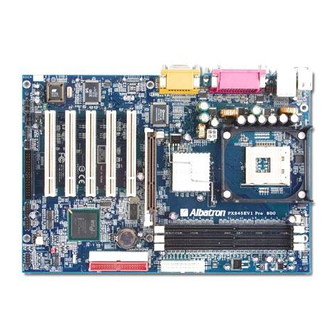
PX845EV1
Copyright
All rights are reserved. No part of this publication may be reproduced, transmitted,
transcribed, stored in a retrieval system or translated into any language or computer language,
in any form or by any means, electronic, mechanical, magnetic, optical, chemical, manual or
otherwise, without the prior written permission of the company. Brands and product names
are trademarks or registered trademarks of their respective companies.
The vendor makes no representations or warranties with respect to the contents herein and
especially disclaim any implied warranties of merchantability or fitness for any purpose.
Further the vendor reserves the right to revise this publication and to make changes to the
contents herein without obligation to notify any party beforehand. Duplication of this
publication, in part or in whole, is not allowed without first obtaining the vendor's approval
in writing.
Disclaimer
We make no warranty of any kind with regard to the content of this user's manual. The
content is subject to change without notice and we will not be responsible for any mistakes
found in this user's manual. All the brand and product names are trademarks of their
respective companies.
FCC Compliance Statement
This equipment has been tested and found to comply with the limits of a Class B digital
device, pursuant to Part 15 of the FCC Rules. These limits are designed to provide
reasonable protection against harmful interference in a residential installation. This
equipment generates, uses and can radiate radio frequency energy and, if not installed and
used in accordance with the instructions, may cause harmful interference to radio
communications. Operation of this equipment in a residential area is likely to cause harmful
interference in which case the user will be required to correct the interference at his own
expense. However, there is no guarantee that interference will not occur in a particular
installation.
Series
120410045M2N
Advertisement
Table of Contents

Related Manuals for Albatron PX845EV1 Series


Summary of Contents for Albatron PX845EV1 Series
-
Page 1: Fcc Compliance Statement
PX845EV1 Series Copyright All rights are reserved. No part of this publication may be reproduced, transmitted, transcribed, stored in a retrieval system or translated into any language or computer language, in any form or by any means, electronic, mechanical, magnetic, optical, chemical, manual or otherwise, without the prior written permission of the company. - Page 2 Update:The new models, the PX845EV1 Rev:800 and PX845EV1 Rev:800 PRO, have been added to this series. They extend from the PX845EV1 series and it supports FSB frequency up to 800 MHz by overclock. They support DDR266/ 200 when installed with CPUs that have clock speeds of 100/ 133 MHz.
- Page 3 PX845EV1 Series ® Intel 82845E & 82801DB ® ® Supports Socket 478 Intel Pentium 4 Processor Enabling the functionality of Hyper-Threading Technology for your computer system requires ALL of the following platform Components CPU: An Intel ® Pentium ® 4 Processor with HT Technology Chipset: An Intel ®...
-
Page 4: Table Of Contents
Contents CHAPTER 1. GETTING STARTED ..................1 ........................1 NTRODUCTION ........................2 PECIFICATIONS ......................6 UICK ONTENT ABLE ........................7 ONFIGURATION ....................9 ARDWARE NSTALLATION CHAPTER 2. BIOS SETUP ....................25 ........................25 NTRODUCTION ......................... 27 BIOS F ....................29 DVANCED EATURES .................... -
Page 5: Chapter 1. Getting Started
4 Processors with a FSB (Front Side Bus) frequency of 400/533 MHz. The PX845EV1 series provides 3 sockets using 184 pin DDR SDRAM with a total capacity of up to 2 GB. You can install DDR 266/200 (PC2100/1600) SDRAM with the option of using the BIOS Setup to over-clock to DDR 400. -
Page 6: Specifications
PX845EV1/ PX845EV1 PRO Specifications CPU: ® ® Supports Intel Socket 478 Pentium 4 processors Speed: 400/533 MHz Front Side Bus frequency Supports core speeds up to 2.8 GHz CPU 33 MHz, 32 bit PCI interface (PCI 2.2 compliant) 66 MHz AGP 2.0 compliant interface that supports 4X data transfer modes (1.5V only) Chipset: Northbridge Chip–... -
Page 7: Flash Memory
PX845EV1/ PX845EV1 PRO BUS Slots: 1 AGP slot (4X/ 1.5V only) Five 32-bit PCI bus slots Flash Memory: Supports flash memory functionality Supports ESCD functionality Hardware Monitor Function: Monitors CPU Fan Speed Monitors Chasis Fan Speed Monitors Auxiliary Fan Speed Monitors System Voltage Infrared: Supports IrDA Version 1.0 SIR Protocol with a maximum baud rate of up to 115.2... -
Page 8: Universal Serial Bus
PX845EV1/ PX845EV1 PRO I/O facilities: One multi-mode Parallel Port capable of supporting the following specifications: 1. Standard & Bi-direction Parallel Port 2. Enhanced Parallel Port (EPP) 3. Extended Capabilities Port (ECP) Supports two serial ports, 16550 UART Supports Infrared Data Transmission using IrDA Supports PS/2 mouse and PS/2 keyboard Supports 360 KB, 720 KB, 1.2 MB, 1.44 MB, and 2.88 MB floppy disk drives MIDI compatible &... -
Page 9: Watch Dog Timer
PX845EV1/ PX845EV1 PRO Watch Dog Timer: This mainboard contains a special feature called the “Watch Dog Timer” which is used to detect when the system is unable to handle over-clocking configurations during POST stage. Once detected the system will reset the configurations and reboot the system after five seconds. -
Page 10: Quick Content Table
PX845EV1/ PX845EV1 PRO Quick Content Table Function Content Location Page CPU Socket 478 DIMM 1、2、3 DDR DIMM Sockets ATX_ PWR、ATX_12V ATX Power Connector IDE Connectors IDE1/IDE2 FDC Connector AGP Slot PCI 1、2、3、4、5 PCI Slots CPU FAN、Chassis FAN、 CPUFAN、CHASFAN、AUXFAN Auxiliary FAN Front Panel Indicator SW/LED Speaker Connector... -
Page 11: Configuration
PX845EV1/ PX845EV1 PRO Configuration Layout of PX845EV1 PRO CPUFAN KB/MS USB/LAN Socket 478 PRT/COM ATX_12V Intel SOUND 82845E AUXFAN Winbond W83627HF PCI1 PCI2 BAT1 PCI3 CHIP Intel IDE2 IDE1 82801DB PCI4 PCI5 Phoenix Bios CHASFAN CASE OPEN CD-IN SPEAKER IrDA USB2 USB3 FRONT AUDIO... - Page 12 PX845EV1/ PX845EV1 PRO Layout of PX845EV1 CPUFAN KB/MS Socket 478 PRT/COM ATX_12V Intel SOUND 82845E AUXFAN Winbond W83627HF PCI1 PCI2 BAT1 PCI3 Intel IDE2 IDE1 82801DB PCI4 PCI5 Phoenix Bios CHASFAN CASE OPEN CD-IN SPEAKER IrDA USB2 USB3 FRONT AUDIO SPDIF SW/LED...
-
Page 13: Hardware Installation
PX845EV1/ PX845EV1 PRO Hardware Installation This section will assist you in quickly installing your system hardware. Wear a wrist ground strap before handling components. Electrostatic discharge may damage your system components. Subject: CPU Processor Installation Memory Installation Back Panel Configuration Connector Configuration Headers &... -
Page 14: Cpu Processor Installation
PX845EV1/ PX845EV1 PRO CPU Processor Installation ® ® This mainboard supports Intel Pentium 4 processors using a Socket 478. Before building your system, we suggest you visit the Intel website and review the processor installation procedures. http://www.intel.com CPU Socket - 478 Configuration Steps: 1. - Page 15 PX845EV1/ PX845EV1 PRO CPU Headers Three power headers are available for cooling fans, which play an important role in maintaining the ambient temperature in your system. We strongly recommend you attach the CPU fan to the “CPUFAN” Header. CPUFAN KB/MS Ground +12V Sense...
- Page 16 PX845EV1/ PX845EV1 PRO Frequency / Voltage Control This mainboard automatically detects and recognizes the CPU ratio. You can otherwise override these values using the BIOS Setup Utility. Configuring the CPU Host Frequency by using the BIOS Setup Utility To access the BIOS Setup Utility, reboot your system. During the reboot process you will be given an opportunity to press the “DEL”...
-
Page 17: Memory Installation
PX845EV1/ PX845EV1 PRO Memory Installation The PX845EV1 series contains 3 sockets, which use 184 pin DDR SDRAM with a total memory capacity of up to 2GB. You can install unbuffered DDR266/ DDR200 (PC2100/ PC1600) SDRAM. Each DIMM socket is capable of using a memory module of up to 1GB. -
Page 18: Back Panel Configuration
USB devices. You can plug the USB devices directly into this connector. The PX845EV1 series also provides two USB headers on the board allowing for 4 more USB ports. These attach to USB connectors embedded into the computer case or connected to a USB connector bracket. -
Page 19: Audio Port Connectors
PX845EV1/ PX845EV1 PRO Serial and Parallel Interface Ports The PX845EV1 series comes equipped with two serial ports and one parallel port. These types of interface ports will be explained below. Print Port COM1 COM2 The Serial Interface Ports: COM1/ COM2 The serial interface port is sometimes referred to as an RS-232 port or an asynchronous communication port. - Page 20 PX845EV1/ PX845EV1 PRO Connector Configuration Front Panel Indicator: SW/LED SW/LED DIMM1 DIMM2 DIMM3 ATX_PWR The layout is PX845EV1 PRO Pin Assignment Function Pin Assignment Function HD LED (+) Hard Drive ACPI LED (+) Power HD LED (-) ACPI LED (-) RST SW (-) Reset PWR SW(+)
- Page 21 PX845EV1/ PX845EV1 PRO SPEAKER (Speaker Connector) An off-board speaker can be connected to this connector. This speaker (onboard or off-board) provides error beep code information during the Power On Self-Test when the computer cannot access the video interface. The speaker cannot be connected to the audio subsystem and can not receive output from the audio subsystem.
- Page 22 PX845EV1/ PX845EV1 PRO Floppy Disk Connector: FDC This mainboard provides a standard floppy disk connector (FDC) that supports 360K, 720K, 1.2M, 1.44M and 2.88M floppy diskettes. This connector supports the floppy drive ribbon cables provided in the packaging. Hard Disk Connectors: IDE1/ IDE2 This mainboard has a 32-bit Enhanced PCI IDE Controller that supports PIO Mode 0~4, Bus Master, Ultra DMA / 33, Ultra DMA / 66,and Ultra DMA / 100.
- Page 23 PX845EV1/ PX845EV1 PRO Headers & Jumpers Front USB Headers: USB2 / USB3 DATA_A- DATA_B- DATA_A+ DATA_B+ Ground Ground USB2 DATA_A- DATA_B- DATA_A+ DATA_B+ DIMM1 Ground Ground DIMM2 DIMM3 USB3 ATX_PWR The layout is PX845EV1 PRO USB Bracket (optional) You can connect the USB bracket to the USB2 and USB3 Headers. * If you are using USB 2.0 devices, you will need to install the USB 2.0 driver from the ®...
- Page 24 PX845EV1/ PX845EV1 PRO Clear CMOS Jumper: JP1 The “Clear CMOS” jumper is used when you cannot boot your system due to some CMOS configuration such as a password that is forgotten. This jumper allows you to reset the CMOS configurations, and then reconfigure. Pin1-2 close Normal (default) DIMM1...
-
Page 25: Audio Connectors
PX845EV1/ PX845EV1 PRO Audio Connectors This mainboard provides three connectors as part of its audio Subsystem. FRONT AUDIO Left Input Ground Ground Right Input CD-IN SPD_OUT Ground SPD_IN DIMM1 SPDIF DIMM2 DIMM3 ATX_PWR The layout is PX845EV1 PRO CD-ROM Audio-In Header: CD-IN This header is used to connect to a CD-ROM / DVD audio cable. - Page 26 PX845EV1/ PX845EV1 PRO Front Panel Audio Header: FRONT AUDIO If your computer case has been designed with embedded audio equipment. You can attach these components to the FRONT AUDIO header of the mainboard. First remove the jumper caps covering the FRONT AUDIO pins. Use pins 1, 3 to connect to the case microphone. Use pins 9,5 to connect to the earphone.
- Page 27 AGP (Accelerated Graphics Port) Slot This mainboard is equipped with a Accelerated Graphics Port (AGP) (1.5v only) to support video cards. The PX845EV1 series also comes with AGP protection which ensures that you only install 1.5V AGP cards. PCI (Peripheral Component Interconnect) Slots This mainboard is equipped with 5 standard PCI slots.
-
Page 28: Power Supply Attachments
PX845EV1/ PX845EV1 PRO Power Supply Attachments ATX Power Connector: ATX_PWR & ATX_12V This mainboard equipments two ATX power connections; a 20-pin connector and a 4-pin connector, your power supply must have both connectors. Attach the 4-pin connector first, then attach the 20-pin connector. Make sure the connectors are secure before applying power. -
Page 29: Chapter 2. Bios Setup
PX845EV1/ PX845EV1 PRO Chapter 2. BIOS Setup Introduction This section describes PHOENIX-AWARD™ BIOS Setup program which resides in the ROM BIOS firmware. The Setup program allows users to modify the basic system configuration. The configuration information is then saved to CMOS RAM where the data is sustained by battery after power-down. -
Page 30: Key Function
PX845EV1/ PX845EV1 PRO DRAM Support DDR (Double Data Rate) SDRAM (Synchronous DRAM) is supported. Supported CPUs ® ® This PHOENIX-AWARD™ BIOS supports the Intel Pentium 4 CPUs. Key Function In general, you can use the arrow keys to highlight items, press <Enter> to select, use the <PgUp>... -
Page 31: Main Menu
PX845EV1/ PX845EV1 PRO Main Menu When you enter the PHOENIX-AWARD™ BIOS Utility, the Main Menu will appear on the screen. The Main menu allows you to select from several configuration options. Use the left/right arrow keys to select a particular configuration screen from the top menu bar or use the down arrow key to access and configure the information below. - Page 32 PX845EV1/ PX845EV1 PRO Main Menu Setup Configuration Options Item Options Description Set the system date. Note that the ‘Day’ automatically Date mm dd yyyy changes when you set the date. Time Hh: mm: ss Set the current time of the system. IDE Primary Options contained in Press <Enter>...
-
Page 33: Advanced Bios Features
PX845EV1/ PX845EV1 PRO Advanced BIOS Features First /Second/Third/ Boot Device Select the order in which devices will be searched in order to find a boot device. Options: Floppy、LS120、HDD-0、SCSI、CDROM、HDD-1、HDD-2、HDD-3、ZIP100、 SB-FDD、USB-ZIP、USB-CDROM、USB-HDD、LAN、Disabled Boot Other Device The setting allows the system to try to boot from other devices if the system fails to boot from the 1st/ 2nd/ 3rd boot devices. -
Page 34: Virus Warning
PX845EV1/ PX845EV1 PRO Advanced BIOS Features Virus Warning This item allows you to choose the VIRUS warning feature for IDE Hard Disk boot sector protection. If this function is enabled and someone attempts to write data into this area, BIOS will display a warning message on the screen and sound an audio alarm (beep). Options: Disabled (default) Virus protection is disabled. -
Page 35: Mps Version Control For Os
PX845EV1/ PX845EV1 PRO MPS Version Control For OS The 1.1 version is the older version that supports 8 more IRQs in the Windows NT environment. Choose the new 1.4 version for Windows 2000 and Windows XP. Options: 1.4 (default)、1.1 OS Select For DRAM > 64MB Select “OS2”... -
Page 36: System Bios Cacheable
PX845EV1/ PX845EV1 PRO DRAM RAS# Precharge This item allows you to select the DRAM RAS# precharge time. The ROW address strobe must precharge again before DRAM is refreshed. An inadequate configuration may result in incomplete data. Options: 3、2 and By SPD (default) DRAM Data Integrity Mode This item can let you choose the DRAM Integrity Mode depending on the type of DRAM installed. -
Page 37: Reset Configuration Data
PX845EV1/ PX845EV1 PRO AGP Aperture Size (MB) Select the size of the AGP (Accelerated Graphics Port) aperture. The aperture is a portion of the PCI memory address range dedicated for graphics memory address space. Host cycles that hit the aperture range are forwarded to the AGP without any translation. Options: 4、8、16、32、64 (default)、128、256 PnP/PCI Configurations Reset Configuration Data... -
Page 38: Pci Slot
PX845EV1/ PX845EV1 PRO PCI SLOT1- 5 This item allows you to select an IRQ address for your PCI slot 1-5. Options: Auto (default)、3、4、5、7、9、10、11、12、14、15 Frequency/Voltage Control Default CPU Voltage (Volt) This item displays the CPU Voltage information which is detected by the system. CPU Clock Ratio Before you configure this option, please make sure that your CPU ratio can be adjusted. - Page 39 PX845EV1/ PX845EV1 PRO AGP Voltage (Volt) This item allows you to adjust the AGP Voltage. Options: 1.5 (default)、1.6 DDR Voltage (Volt) This item allows you to adjust the RAM voltage. Options: 2.5 (default)、2.6、2.7、2.8...
-
Page 40: Integrated Peripherals
PX845EV1/ PX845EV1 PRO Integrated Peripherals INTEL OnChip IDE Device On-Chip Primary/Secondary PCI IDE The mainboard chipset contains a PCI IDE interface with support for two IDE channels. Select “Enabled” to activate the first and/or second IDE interface. Select “Disabled” to deactivate the interface if you are going to install a primary and/or secondary add-in IDE interface. -
Page 41: Ide Hdd Block Mode
PX845EV1/ PX845EV1 PRO IDE HDD Block Mode Block mode is otherwise known as block transfer, multiple commands, or multiple sector read/write. Select the “Enabled” option if your IDE hard drive supports block mode (most new drives do). The system will automatically determine the optimal number of blocks to read and write per sector. -
Page 42: Power On Function
PX845EV1/ PX845EV1 PRO Power On Function This option allows you to select a way to power on your computer. Options: Password、Hot KEY、Mouse Left、Mouse Right、Any KEY、BUTTON ONLY (default), and Keyboard 98 KB Power On Password Supply a password that your system will use as part of the power-on sequence. Hot Key Power ON This option allows you to use the Ctrl key along with a hot key (function key) to power on your system. -
Page 43: Use Ir Pins
PX845EV1/ PX845EV1 PRO Use IR Pins Consult your IR peripheral documentation to select the correct setting of the TxD and RxD signals. Options: Full、Half (default) Onboard Parallel Port Select an address and corresponding interrupt for the onboard parallel port. Options: 378/IRQ7 (default)、278/IRQ5、3BC/IRQ7、Disabled Parallel Port Mode This option allows you to select an parallel port mode for the on board parallel port. -
Page 44: Power Management
PX845EV1/ PX845EV1 PRO Power Management The Power Management Setup Menu allows you to configure your system to utilize energy conservation features as well as power-up/ power-down options. ACPI Suspend Type The item allows you to select the suspend type using the ACPI operating system. Options: S1 (POS) (default) Power on Suspend... -
Page 45: Video Off Method
PX845EV1/ PX845EV1 PRO 2. Max. Power Saving Maximum power management (only available for sl CPUs). Suspend Mode = 1 min. HDD Power Down = 6 min. 3. User Defined (default) Allows you to set each mode individually. When this option is enabled, each of the ranges are from 1 min. to 1 hr. except for HDD Power Down, which ranges from 1 min. - Page 46 PX845EV1/ PX845EV1 PRO Soft-Off by PWRBTN Pressing the power button for more than 4 seconds forces the system to enter the Soft-Off state when the system has “hung.” Options: Delay 4 Sec, Instant-Off (default). Wake Up Control If you highlight the “Wake Up Control” label and then press the enter key, it will display a submenu with the following options: PCI PME Wake Up When you select “Enabled”, a PME signal from any PCI 2.2 card will awaken the system.
-
Page 47: Hardware Monitor
PX845EV1/ PX845EV1 PRO Hardware Monitor Case Open Warning If this function is set to “Enabled” and the case had been previously opened, the system will automatically display alert messages on the screen when you power on your computer. If this function is set to “Disabled”, the system will not show alert messages when you power on your computer even if the case is opened by others. -
Page 48: Load Defaults
PX845EV1/ PX845EV1 PRO Load Defaults Load System Default Settings Load System Default Settings. Load System turbo Settings Load System Turbo Settings. Load CMOS From BIOS Load defaults from flash ROM for systems without batteries. Save CMOS To BIOS Save defaults to flash ROM for systems without batteries. -
Page 49: Exit Menu
PX845EV1/ PX845EV1 PRO Exit Menu Save & Exit Setup Save all configuration changes to CMOS (memory) and exit setup. A confirmation message will be displayed before proceeding. Exit Without Saving Abandon all changes made during the current session and exit setup. A confirmation message will be displayed before proceeding. -
Page 50: Chapter 3: Software Setup
PX845EV1/ PX845EV1 PRO Chapter 3: Software Setup Software List Category Platform Intel Chipset INF update Intel IAA Utility Realtek Audio Driver Windows 9X/2000 /ME/XP/NT4 3Com Lan Driver PC-Cillin 2002 Acrobat Reader 5.0 Software Installation Place the Driver CD into the CD-ROM drive and the Installation Utility will auto-run. You can also launch the Driver CD Installation Utility manually. - Page 51 PX845EV1/ PX845EV1 PRO 2. On the “PX845EV/PX845EV1(PRO)” screen, click “Mainboard Driver”. 3. On the “Mainboard Driver” screen, use the buttons displayed on the screen to install their respective software. 4. By clicking “Tools” from the screen in step 2, the screen will be displayed with options to install two programs.
-
Page 52: Super 5.1 Channel Setup
PX845EV1/ PX845EV1 PRO Super 5.1 Channel Setup 1. After into the system, click the audio icon from the Windows screen. 2. Click Speaker Configuration button, you can see the screen like the picture below. 3. You can choice 2, 4 or 6 channels by your speakers. 2 Channels 4 Channels 6 Channels... -
Page 53: Chapter 4: Troubleshooting
PX845EV1/ PX845EV1 PRO Chapter 4: Troubleshooting Problem 1: No power to the system. Power light does not illuminate. Fan inside power supply does not turn on. Indicator lights on keyboard are not lit. Causes: 1. Power cable is unplugged. 2. Defective power cable. 3. - Page 54 PX845EV1/ PX845EV1 PRO Problem 4: System only boots from the CD-ROM. The hard disk can be read and applications can be used but booting from the hard disk is impossible. Causes: Hard Disk boot sector has been corrupted. Solutions: Back up data and applications files. Reformat the hard drive. Re-install applications and data using backup disks.
- Page 55 PX845EV1/ PX845EV1 PRO Problem 10: Keyboard failure. Causes: Keyboard is disconnected. Solutions: Reconnect keyboard. Replace keyboard if you continue to experience problems. Problem 11: No color on screen. Causes: 1. Faulty Monitor. 2. CMOS incorrectly set up. Solutions: 1. If possible, connect monitor to another system. If no color appears, replace monitor. 2.
-
Page 56: Appendix I: 2 To 3-Pin Adapter
PX845EV1/ PX845EV1 PRO Appendix I: 2 to 3-pin adapter This mainboard complies with the ATX standard, which means the ACPI connector on this board is 2-pin. If the Power LED cable of your case uses a 3-pin adapter, you must use the 2-pin to 3-pin adapter (contained in the packaging).
Need help?
Do you have a question about the PX845EV1 Series and is the answer not in the manual?
Questions and answers