Table of Contents
Advertisement
Quick Links
Copyright
All rights are reserved. No part of this publication may be reproduced, transmitted, transcribed,
stored in a retrieval system or translated into any language or computer language, in any form or by
any means, electronic, mechanical, magnetic, optical, chemical, manual or otherwise, without the
prior written permission of the company. Brands and product names are trademarks or registered
trademarks of their respective companies.
The vendor makes no representations or warranties with respect to the contents herein and especially
disclaim any implied warranties of merchantability or fitness for any purpose. Further the vendor
reserves the right to revise this publication and to make changes to the contents herein without
obligation to notify any party beforehand. Duplication of this publication, in part or in whole, is not
allowed without first obtaining the vendor's approval in writing.
Disclaimer
We make no warranty of any kind with regard to the content of this user's manual. The content is
subject to change without notice and we will not be responsible for any mistakes found in this user's
manual. All the brand and product names are trademarks of their respective companies.
FCC Compliance Statement
This equipment has been tested and found to comply with the limits of a Class B digital device,
pursuant to Part 15 of the FCC Rules. These limits are designed to provide reasonable protection
against harmful interference in a residential installation. This equipment generates, uses and can
radiate radio frequency energy and, if not installed and used in accordance with the instructions, may
cause harmful interference to radio communications. Operation of this equipment in a residential area
is likely to cause harmful interference in which case the user will be required to correct the
interference at his own expense. However, there is no guarantee that interference will not occur in a
particular installation.
PX865PE7 Series
120410101M1N
Advertisement
Table of Contents

Related Manuals for Albatron PX865PE7


Summary of Contents for Albatron PX865PE7
-
Page 1: Fcc Compliance Statement
PX865PE7 Series Copyright All rights are reserved. No part of this publication may be reproduced, transmitted, transcribed, stored in a retrieval system or translated into any language or computer language, in any form or by any means, electronic, mechanical, magnetic, optical, chemical, manual or otherwise, without the prior written permission of the company. -
Page 2: Package Contents
FDC Cable USB Bracket (optional) SPDIF & FRONT AUDIO Port Bracket (optional) SATA Power cord (optional) SATA Cable (optional) Installation and Setup Driver CD PX865PE7 Series User Manual Symbols Following the procedures … PX865PE7 Series Attention … Troubleshooting … Please refer to …... -
Page 3: Operating System
Intel Supports Socket 775 Intel User Manual Enabling Hyper-Threading for your computer system requires ALL of the following components ® CPU: An Intel Pentium ® Chipset: An Intel Chipset that supports HT Technology BIOS: A BIOS that supports HT Technology must be enabled... -
Page 4: Table Of Contents
CHAPTER 1. GETTING STARTED ...1 ... 1 NTRODUCTION ... 2 PECIFICATION ... 5 ONFIGURATION Layout of PX865PE7 PRO ... 5 Layout of PX865PE7... 5 ... 7 ARDWARE NSTALLATION CPU Processor Installation ... 7 Memory Installation ... 8 Back Panel Configuration... 10 Connectors ... -
Page 5: Chapter 1. Getting Started
Southbridge chipset. It supports Intel of 533/ 800 MHz. The PX865PE7 series provides 4 DIMM slots using 184 pin DDR SDRAM with a total capacity of up to 4GB. You can install unbuffered & non-ECC DDR400/ 333/ 266 (PC3200/ 2700/ 2100) DIMMs. -
Page 6: Specification
Southbridge Chip (ICH) – Intel ICH5 I/O Controller – Winbond W83627THF AC’97 Codec – Realtek ALC655 Gb LAN Controller – Marvell MV8001 (Only for PX865PE7 PRO) DRAM Memory: Supports DDR400 (PC3200)/ DDR333 (PC2700)/ DDR266 (PC2100) SDRAM DIMMs Supports 64 MB/ 128 MB/ 256 MB/ 512 MB/ 1 GB unbuffered & non-ECC DIMM... -
Page 7: Universal Serial Bus
Supports IrDA Version 1.0 SIR Protocol with a maximum baud rate of up to 115.2 Kbps Supports SHARP ASK-IR Protocol with maximum baud rate of up to 57600 bps Marvell LAN Chip on board: (only for PX865PE7 PRO) Supports Ethernet 10/ 100/ 1000 Mbit/s connectivity AC’97 Sound Codec Onboard:... -
Page 8: Watch Dog Timer
This mainboard contains a special feature called the “Watch Dog Timer” which is used to detect when the system is unable to handle over-clocking configurations during the POST stage. Once a problem is detected the system will reset the configurations and reboot the system after five seconds. PX865PE7 PRO/ PX865PE7... -
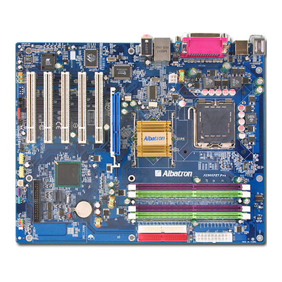
Page 9: Configuration
PX865PE7 PRO/ PX865PE7 Configuration Layout of PX865PE7 PRO Layout of PX865PE7... - Page 10 PX865PE7 PRO/ PX865PE7...
-
Page 11: Hardware Installation
CPU Processor Installation ® This mainboard supports Intel Pentium system, we suggest you visit the Intel website and review the processor installation procedures. http://www.intel.com CPU Socket 775 Configuration Steps: 1. Locate the CPU socket 775 on your mainboard and nudge the lever away from the socket as shown. -
Page 12: Fan Headers
CPUs that have CPU clock speeds of 200 MHz. The series provides Dual-Channel functionality for its DIMM slots. DIMM1 and DIMM2 share one channel, while DIMM3 and DIMM4 share the other channel. Enabling dual channels can increase your data access rates. PX865PE7 PRO/ PX865PE7... -
Page 13: Ram Module Installation
3. Lower the RAM module into the DIMM Slot and press firmly using both thumbs until the module snaps into place. 4. Repeat steps 1,2 &3 for the remaining RAM modules. * The pictures above are for reference only. PX865PE7 PRO/ PX865PE7 DIMM3 DIMM4... -
Page 14: Back Panel Configuration
There are four USB connectors on the back panel. These USB connectors are used to attach to USB devices such as: keyboards, mice and other USB devices. You can plug the USB devices directly into this connector. The PX865PE7 PRO also provides a LAN port. You can plug LAN devices directly into this connector. -
Page 15: Audio Port Connectors
Subwoofer/ Center out. This mainboard supports Super 5.1 Channel Audio effects which turns your standard Speaker Out, Lin In, Mic In audio connectors into a 6 channel audio system. See Appendix II for more information. PX865PE7 PRO/ PX865PE7 Printer Port COM1 COM2... -
Page 16: Connectors
IDE1. The second drive on this controller must be set to slave mode. SATA1/ SATA2 These SATA connectors support Serial ATA 150. These connectors only can connect to one serial ATA hard disk each. Front Panel Indicator: SW/LED、PWRLED、SPEAKER PX865PE7 PRO/ PX865PE7... - Page 17 A front panel speaker can be attached to this connecto the boot up process (Power On Self-Tes signal problems PX865PE7 PRO/ PX865PE7 and run the POST (Power On Self Test). o the 2-pin power LED connector. The LED will switch. The switch must pull the Power Button wer supply to switch on or off (the time required is nector.
-
Page 18: Headers & Jumpers
When your computer case is opened, your system will show alert messages during boot up. To use this function, your computer case must be equipped with a “case open” cable. PX865PE7 PRO/ PX865PE7 ® website. If you are using Service ®... -
Page 19: Infrared Header: Irda
1. Turn off your system and disconnect the AC power cable. 2. Set JP1 to OFF (2-3 Closed). 3. Wait several seconds. 4. Set JP1 to ON (1-2 closed). 5. Connect the AC power cable and turn on your system. 6. Reset your new password. PX865PE7 PRO/ PX865PE7... -
Page 20: Audio Connectors
If you do not intend to use the FRONT_AUDIO panel, do not remove the jumper caps. Attention If the jumper caps are in place, jumper cap 1 is on pin 5, pin 6 and jumper cap2 is on pin 9, pin 10. PX865PE7 PRO/ PX865PE7... -
Page 21: Slots
This mainboard requires two ATX power connections; a 20-pin connector and a 4-pin connector. Your power supply must have both connectors. Attach the 4-pin connector first, then attach the 20-pin connector. Make sure the connectors are secure before applying power. PX865PE7 PRO/ PX865PE7... -
Page 22: Chapter 2. Bios Setup
These features include system sleep and suspend modes in addition to hard disk d monitor sleep modes. Power management features are implemented using the System Management Interrupt (SMI). CI Bus Support This PHOENIX-AWARD™ BIOS also supports Version 2.3 of the Intel PCI (Peripheral Component Interconnect) local bus specification. PX865PE7 PRO/ PX865PE7 ®... -
Page 23: Key Function
Page Setup Menu and Option Page Setup Menu – Exit F1 key F5 key F6 key F7 key F10 key PX865PE7 PRO/ PX865PE7 ® ® s the Intel Pentium 4 CPUs. F1> for help and press <Esc> to quit. The following table... -
Page 24: Main Menu
Main menu allows you to select from several configuration options. Use the left/right arrow keys select a particular configuration screen from the top menu bar or use the down arrow key to access d configure the information below. PX865PE7 PRO/ PX865PE7... - Page 25 Base Memory Extended Memory Total Memory PX865PE7 PRO/ PX865PE7 Description Set the system date. Note that the ‘Day’ automatically changes when you set the date. Set the current time of the system. Press <Enter> to enter the sub menu.
-
Page 26: Advanced Bios Features
Only 360 KB floppy drivers have 40 tracks. Drives with 720 KB, 1.2 MB and 1.44 MB capacity have 80 tracks. Because very few modern PCs have 40-tracks floppy drivers, we recommend that you set this field to “Disabled”. Options: Enabled、Disabled (default) PX865PE7 PRO/ PX865PE7 e floppy, LS120, ZIP-100, USB-FDD and USB-ZIP. er to find a boot device. -
Page 27: Advanced Bios Features
When “Enabled”, the “typematic rate” and “ determines the keystroke repeat rate used by the keyboard controller.. Options: Disabled (default)、Enabled PX865PE7 PRO/ PX865PE7 alarm (beep). hreading Technolong. And this item will allow you to typematic delay” can be configured. Typematic Rate... -
Page 28: Advanced Chipset Features
PX865PE7 PRO/ PX865PE7 Typematic Rate (Chars/Sec) The rate at which a character repeats when you hold down a key. 、8、10、12、15、20、24、30 Options: 6 (default) Typematic Delay (Msec) The delay before keystrokes begin to repeat. Options: 250 (default)、500、750、1000 APIC Mode By enabling this option, “MPS version control for OS”... -
Page 29: Video Bios Cacheable
PX865PE7 PRO/ PX865PE7 Active to Precharge Delay This item allows you to select DRAM Active to Precharge Delay. This field is locked when “DRAM Timing Selectable” is set to “By SPD” and is automati cally determined by the system. 、 、 、5... -
Page 30: Pnp/Pci Configuration Reset Configuration Data
PCI Latency Timer (CLK) his item allows you to set up the PCI Latency Time (0-255). If you select the “32” it will optimize PCI speeds. Options: 0-255、32 (default) PX865PE7 PRO/ PX865PE7 can be increased about 3%~5%. conflict that the OS cannot... -
Page 31: Cpu Clock Ratio
DDR Speed This item displays the current DDR memory speed. Spread Sp ctrum The Spread Spectrum function can reduce th Enabled (default)、Disabled PX865PE7 PRO/ PX865PE7 U Clock Ratio” and overclock the DDR speeds of Available Options Default (default)、2.00X、2.50X、 1.33X (Debug)、1.60X (Debug) Default (default)、1.33X、1.60X、2.00X... - Page 32 This item allows yo u to adjust the RAM voltage. Options: Default (default)、Default + 0.3V、Default + 0.2V、Default + 0.1V PX865PE7 PRO/ PX865PE7 (speed settings). You can set these available to you is “Auto, Auto, tion wi instruc t the y...
-
Page 33: Integrated Peripherals
PX865PE7 PRO/ PX865PE7 tegrated Peripherals Init Display First With systems that have multiple video cards, this option determines whether the primary display uses a PCI slot or an AGP slot. Options: AGP (default)、PCI Slot OnChip IDE Device IDE HDD Block Mode Block mode is o herwise known as block transfer, multiple commands, or multiple sector read/write. -
Page 34: Onboard Device
This option should be enabled if your system has a USB port installed on the system board. You will need to disable this feature if you add a higher performance controller. Options: Enabled (default)、Disabled PX865PE7 PRO/ PX865PE7 Enhanced Mode Combined Mode... -
Page 35: Usb Keyboard Support
AC97 Audio This item al lows you to control the onboard AC’97 audio. Options: Enabled (default)、Disabled Onboard LAN Device (only for PX865PE7 PRO) This item allows you to enable or disable the LAN Device. Options: Enabled (default)、Disabled Onboard I/O Chip Setup... -
Page 36: Ir Transmission Delay
Normal EPP Mode Select Select EPP port type 1.7 or 1.9. This field is on or “ECP+EPP”. Options: EPP 1.9(default)、EPP 1.7 PX865PE7 PRO/ PX865PE7 Red (IR) standard to be used. IrDA y the IR interface. Full-duplex mode permits simultaneous abilities Port. -
Page 37: Power Management
Options: Auto (default)、Yes、No Power Managem There are three options of Power Management: 1. Min. Saving inimum power management PX865PE7 PRO/ PX865PE7 rating system. Power on Suspend Suspend to RAM POS and STR system wakes up from the S3 suspend function. -
Page 38: Hdd Power Down
All other devices remain active. Options: Disabled (default)、1 Min、2 Min、3 M 、12 Min、13 Min、14 Min、15Min 10 Min、11 Min PX865PE7 PRO/ PX865PE7 end type under the ACPI operating system. 5、7、9、10、11、NA. the ACPI operating system. ill power down after a certain configurable period of system... -
Page 39: Soft-Off By Pwrbtn
Devices include: Primary IDE 0/ Primary IDE 1/ Secondary IDE 0/ Secondary IDE 1/ FDD,COM,LPT Port/ PCI PIRQ [A-D]#. Options: Disabled (default), Enable PX865PE7 PRO/ PX865PE7 ode using a USB keyboard. t to S3. -
Page 40: Hardware Monitor
Options: Disabled (default)、30 C / 86 F、35 C / 131 F、60 C / 140 F、65 C / 149 PX865PE7 PRO/ PX865PE7 N temperature. If the CPU temperature is lower then the nd the CPUFAN will slowdown. C / 95 F、40 C / 104 F、45... -
Page 41: Load Defaults
PX865PE7 PRO/ PX865PE7 Load Defaults Load System Default Settings Load System Default Settings. Load System Turbo Settings Load System Turbo Settings. Load CMOS From BIOS Load defaults from flash ROM for systems without ba tteries. Save CMOS To BIOS Save defaults to flash ROM for systems without batteries. -
Page 42: Exit Menu
PX865PE7 PRO/ PX865PE7 Exit Menu Save & Exit Setup Save all configuration changes to CMOS (memory) and exit setup. A confirmation message will be isplayed before proceeding. Exit Without Sav bandon all changes made during the current session and exit setup. A confirmation message will be... -
Page 43: Chapter 3: Software Setup
Software Inst allation Place the Driver CD into the CD-ROM drive and the Installation Utility will auto-run. You can also launch the Driver CD Installation Utility manually by executing the Intel.exe program located on the Driver CD. (For more details, please refer to the Readme.txt files that in each folder of the Driver.) - Page 44 Realtek Audio Driver – provides the driver of Realtek Au Intel USB 2.0 Driver – follow the description to complete the installation. Marvell Lan Driver – provides driver of Marvel 3. Click the “Tools” on the main screen and you can Trend PC-Cillin 2004 –...
-
Page 45: Chapter 4: Troubleshooting
1. Check the cable running from the disk to the disk controller board. Make sure both ends are securely attached. Check the drive type in the standard CMOS setup. 2. Contact technical support. 3. Backing up the hard drive is extremely important. Make sure your periodically perform backups to avoid untimely disk crashes. PX865PE7 PRO/ PX865PE7... - Page 46 2. Use anti-virus programs to detect and clea Problem 9: Screen goes blank periodically Causes: Screen saver is enabled. Solutions: Disable screen saver. PX865PE7 PRO/ PX865PE7 PX865PE7 PRO/ PX865PE7 FOUND” displays and the system does not allow certain data intrusion or disk failure. when completed.
- Page 47 CMOS setup has been changed. Solutions: Run se tup and select the correct drive type. Problem 15: Certain keys do not function. Causes: Keys jammed or defective. Solutions: Replace keyboard. PX865PE7 PRO/ PX865PE7 f you continue to experience problems.
-
Page 48: Appendix I: Over Clocking
BIOS Setup Utility and changing “DDR:CPU R Frequency”. Note that the FSB m ultiplier for Intel based mainboards will always be fixed at 4. The AGP, PCI and SRC frequencies ar e all determined by the BIOS setting AGP/ PCI/ SRC Speed Setting. - Page 49 BIOS Setup Utility. The CPU, AGP and DDR all have individual configurable voltage options. Spread Spectrum We recommend that you disable this function before you overclock your system. PX865PE7 PRO/ PX865PE7 PX865PE7 PRO/ PX865PE7 ariables es in the BIOS Setup Utility that are related to overclock nal information about these fields including available e the CPU Speed.
-
Page 50: Configuration Suggestions
When you do increase the voltages, inc rease them only one increment at a time. PX865PE7 PRO/ PX865PE7 = current CPU Host Frequency / 2 = current CPU Host Frequency / 4 = current CPU Host Frequency / 1.33... - Page 51 If the last POST status was “not successful”, it will be assumed there were configuration problems and the system will automatically reset the BIOS configurations which will allow your system to boot again. PX865PE7 PRO/ PX865PE7 ur m ainboard.
- Page 52 This example shows you how to overclock the CPU Internal Clock, DDR frequency and FSB frequency for an Intel based mainboard. Note that the options that are supplied with your version of the BIOS may vary slightly. The example is for reference only.
-
Page 53: Appendix Ii: Super 5.1 Channel Setup
2. Click Sp eaker Test button, you can 3. Select th e speaker which you want to test b hannels PX865PE7 PRO/ PX865PE7 from the Windows screen. 4 Channels 6 Channels hich supports high quality 5.1 Channel audio effects. se this funct... -
Page 54: Appendix Iii: How To Install Windows 98/ Me To The Sata Device
98/ ME, you must had the SATA channel). So that you should set the “On-Ch time in the BIOS Setup Utility. PX865PE7 PRO/ PX865PE7 set to “ Combined Mode” in the BIOS Setup OnChip IDE Device On-Chip Serial ATA ®...
Need help?
Do you have a question about the PX865PE7 and is the answer not in the manual?
Questions and answers