Table of Contents
Advertisement
Copyright
All rights are reserved. No part of this publication may be reproduced, transmitted,
transcribed, stored in a retrieval system or translated into any language or computer
language, in any form or by any means, electronic, mechanical, magnetic, optical,
chemical, manual or otherwise, without the prior written permission of the company.
Brands and product names are trademarks or registered trademarks of their respective
companies.
The vendor makes no representations or warranties with respect to the contents herein
and especially disclaim any implied warranties of merchantability or fitness for any
purpose. Further the vendor reserves the right to revise this publication and to make
changes to the contents herein without obligation to notify any party beforehand.
Duplication of this publication, in part or in whole, is not allowed without first obtaining
the vendor's approval in writing.
Trademark
All the trademarks or brands in this document are registered by their respective owner.
Disclaimer
We make no warranty of any kind with regard to the content of this user's manual. The
content is subject to change without notice and we will not be responsible for any
mistakes found in this user's manual. All the brand and product names are trademarks of
their respective companies.
FCC Compliance Statement
This equipment has been tested and found to comply with the limits of a Class B digital
device, pursuant to Part 15 of the FCC Rules. These limits are designed to provide
reasonable protection against harmful interference in a residential installation. This
equipment generates, uses and can radiate radio frequency energy and, if not installed
and used in accordance with the instructions, may cause harmful interference to radio
communications. Operation of this equipment in a residential area is likely to cause
harmful interference in which case the user will be required to correct the interference
at his own expense. However, there is no guarantee that interference will not occur in a
particular installation.
CE Mark
The device is in accordance with 89/336 ECC-ENC Directive.
Ver: EG101
P4M800-775
Advertisement
Table of Contents

Related Manuals for Albatron P4M800-775


Summary of Contents for Albatron P4M800-775
-
Page 1: Fcc Compliance Statement
P4M800-775 Copyright All rights are reserved. No part of this publication may be reproduced, transmitted, transcribed, stored in a retrieval system or translated into any language or computer language, in any form or by any means, electronic, mechanical, magnetic, optical, chemical, manual or otherwise, without the prior written permission of the company. - Page 2 P4M800-775 ® P4M800 & VT8237R Support Socket 775 ® ® Intel Pentium 4 Prescott Processor User Manual enable Hyper-Threading (HT) Technology, your computer system required have following components: CPU: An Intel ® Pentium ® 4 Processor with HT Technology Chipset: An Intel ®...
-
Page 3: Packing List
Do not touch any IC chip, lead, connector or other components. Unplug the AC power when you install or remove any device on the mainboard. Packing List P4M800-775 mainboard FDD Cable HDD Cable I/O Bracket (for ATX case) USB 2.0 Cable (Optional) -
Page 4: Table Of Contents
Table of Contents CHAPTER 1. GETTING STARTED ..............1 ....................... 1 NTRODUCTION ....................... 2 PECIFICATION ....................5 ONFIGURATION Layout of P4M800-775 ................... 5 ................... 6 ARDWARE NSTALLATION CPU Processor Installation................6 Memory Installation ..................7 Back Panel Configuration................8 Connectors..................... 10 Front Panel Headers.................. -
Page 5: Chapter 1. Getting Started
(Super 5.1 Channel Audio Effect) (See Appendix I). The mainboard also supports the Sony/Philips Digital Interfaces (SPDIF) function (optional). The P4M800-775 comes with an onboard 10/100 Mbps Ethernet LAN chip. There is a LAN port on the back panel that you can directly plug an internet cable into. -
Page 6: Specification
Specification CPU: Support Socket 775 Pentium ® 4 Prescott processor Support Hyper-Threading Technology Support FSB (Front Side Bus) 533/ 800 MHz Chipset: Northbridge Chipset – VIA® P4M800 Southbridge Chipset – VIA® VT8237R I/O Controller – ITE® IT8705AF AC’ 97 Aduio Codec – Realtek® ALC655 LAN Controller –... -
Page 7: Universal Serial Bus
Onboard AC’ 97 Sound Codec: High performance Codec with high S/N ratio (>90 db) Compliant with AC’ 97 2.3 specification Support 6-channel playback capability (Super 5.1 Channel Audio Effect) Support 3D stereo enhancement Support Sony/ Philips Digital Interfaces (S/PDIF) function (Optional) Onboard LAN Chip: 10/100 Mbps Ethernet LAN supported I/O facilities:... -
Page 8: Watch Dog Timer
Hardware Monitor Function: Monitor CPU/ Chassis Fan Speed Monitor CPU and system temperature Monitor system voltages Watch Dog Timer: This function is for detecting the system when it is unable to handle over-clocking configurations during the POST stage. Once the problem is detected, the system will reset the configurations and reboot the system within five seconds. -
Page 9: Configuration
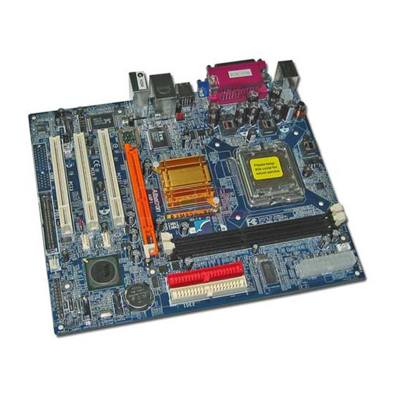
Configuration Layout of P4M800-775... -
Page 10: Hardware Installation
Hardware Installation This section will assist you in quickly installing your system hardware. Wear a wrist ground strap before handling components. Electrostatic discharge may damage the system’s components. CPU Processor Installation This mainboard supports Intel Pentium 4 processors using a Socket 775. Before building ®... -
Page 11: Memory Installation
FAN Headers: JCFAN1, JSFAN1 Two power headers for cooling fans are available on the P4M800-775. The cooling fans are playing important roles in maintaining CPU and ambient temperatures in your system. Please attach the fan power cords to these two headers. -
Page 12: Back Panel Configuration
1. Pull the white plastic tabs at both ends of the socket away. 2. Align a memory on the socket such that the notch on the memory matches the break on the socket. 3. Lower the memory vertically into the socket and press firmly by using both thumbs until the memory snaps into place. - Page 13 PS/2 Mouse & PS/2 Keyboard Ports: JKBMS1 This mainboard provides a standard PS/2 mouse port and a PS/2 keyboard port. The pin assignments are described below. PS/2 Mouse Assignment Assignment Data +5 V (fused) Clock Ground PS/2 Keyboard Serial and Parallel Interface Ports The mainboard provides one serial port, one parallel port, and one VGA port on the back panel.
-
Page 14: Connectors
Audio Ports: Sound This mainboard provides three Audio Ports. The Mic-in, Line-in and Line-out are standard audio ports that provide basic audio function. Line-In (Blue) This port is used to attach an external audio device such as a CD player, tape player or other audio device that has an audio input connector. -
Page 15: Front Panel Headers
Secondary IDE Connector: IDE2 The IDE2 connector can also be attached with two HDDs by IDE ribbon cable; however, you also must configure one as the Master and the other one as the Slave. SATA Connector: SATA1/2 The two SATA connectors support a transfer rate of 150 Mbps and SATA RAID 0/1 mode. One SATA connector only can attach one SATA HDD of each time. -
Page 16: Headers & Jumpers
Speaker Header (Green): SPK A PC front panel speaker cord can attach onto this header. When you reboot the system, the speaker will sound a short “beep”. If there is something wrong during the Power On Self-Test, the speaker otherwise will sound “irregular beep” to warn you. Hard Drive LED Header (Orange): HLED This header can be attached with a PC front panel LED cord. - Page 17 front panel. An optional USB bracket may be included within this product and you can attach more USB devices on it. Assignment Assignment +5V (fused) +5V (fused) USB- USB- USB+ USB+ JUSB3/JUSB4 Ground Ground Attention If you are using a USB 2.0 device with Windows 2000/XP, you will need to install the USB 2.0 driver from the Microsoft ®...
-
Page 18: Audio Configuration
The following steps explain how to reset your CMOS configurations when you forgot a system password. 1. Turn off your system and disconnect the AC power cable. 2. Set JP1 header to OFF (2-3 Closed). 3. Wait several seconds. 4. Set JP1 header to ON (1-2 closed). 5. -
Page 19: Slots
RCA or Tos-Link connector will be on the bracket and convenient you to output or input data into the SPDIF devices. Assignment SPDIF out JSPDIFO1 Ground Slots AGP Slot: AGP1 The mainboard supports to install an extra graphics card with AGP interface or PCI interface, in order to improve your display efficiency and performance. -
Page 20: Chapter 2. Bios Setup
Assignment Assignment +12V Ground JATXPWR2 +12V Ground Attention In general, power cords are designed and should be attached with a specific direction. The black wire of the power cord is Ground and should be attached onto the header location of Ground. -
Page 21: Menu Description
Keystroke Function Up arrow Move to previous option Down arrow Move to next option Left arrow Move to the option on the left (menu bar) Right arrow Move to the option on the right (menu bar) Main Menu: Quit without saving changes Submenus: Exit Current page to the next higher level menu Move Enter Move to the option you desire... -
Page 22: Load Optimized Defaults
Load Optimized Defaults It can load the preset system parameter values to set the system in its best performance configurations. Set Supervisor Password Set change or disable password. It allows you to limit access to the system and/or BIOS setup. Set User Password Set change or disable password. -
Page 23: Chapter 3: Troubleshooting
Chapter 3: Troubleshooting Problem 1: No power to the system. Power light does not illuminate. Fan inside power supply does not turn on. Indicator lights on keyboard are not lit. Causes: 1. Power cable is unplugged. 2. Defective power cable. 3. - Page 24 Problem 4: System only boots from the CD-ROM. The hard disk can be read and applications can be used but booting from the hard disk is impossible. Causes: Hard Disk boot sector has been corrupted. Solutions: Back up data and applications files. Reformat the hard drive. Re-install applications and data using backup disks.
- Page 25 Problem 10: Keyboard failure. Causes: Keyboard is disconnected. Solutions: Reconnect keyboard. Replace keyboard if you continue to experience problems. Problem 11: No color on screen. Causes: 1. Faulty Monitor. 2. CMOS incorrectly set up. Solutions: 1. If possible, connect monitor to another system. If no color appears, replace monitor. 2.
-
Page 26: Appendix I: Super 5.1 Channel Audio Effect Setup
Appendix I: Super 5.1 Channel Audio Effect Setup Channels Setup 1. After getting into the system, click the audio icon from the Windows screen. 2. Click Speaker Configuration button, you can see the screen like the picture below. 3. You can choose 2, 4 or 6 channels by your speakers. 2 Channels 4 Channels 6 Channels... -
Page 27: Appendix Ii: Sata Raid 0/1 Setup
Appendix II: SATA RAID 0/1 Setup Introduction to RAID (Redundant Array of Independent Disks) RAID technology is a sophisticated disk management system that manages multiple disk drives, enhancing I/O performance and providing redundancy in order to prevent the loss of data in case any of the individual disks fail. The SATA RAID facility on this board provides RAID 0 (striped), RAID 1 (mirrored) and RAID SPAN. -
Page 28: Create Array
Create Array The “Create Array” option will allow you to initialize a RAID array. Choose the “Create Array” on the main screen and press <Enter>. The screen below will display. According to your needs, select “RAID 0 for performance” (striping), “RAID 1 for data protection”... - Page 29 After the array has been successfully created, one of the screens will display as shown below according to the type of array you created. RAID 1 mode RAID 0 mode RAID SPAN mode The RAID 0 screen (above) contains the option, “Block Size 64K”. With this option you can manually select the block size for your array.
-
Page 30: Delete Array
Delete Array You can delete an existing array with the “Delete Array” option on the main screen. Choose the “Delete Array” option and press <Enter>. Then press the <Enter> key once again and the system will mark all the existing SATA devices with an asterisk (as shown below in the bottom section). -
Page 31: Serial Number View
Serial Number View You can choose the “Serial Number View” to view the serial number of the serial ATA device. The serial number is assigned to the device by the manufacturer. VIA RAID Tool (VIA Raid Tool icon The VIA RAID Tool allows the user to configure and monitor RAID arrays from the Windows environment.