
Related Manuals for Runco Reflection VX-3c


Summary of Contents for Runco Reflection VX-3c
-
Page 1: Vhd Controller
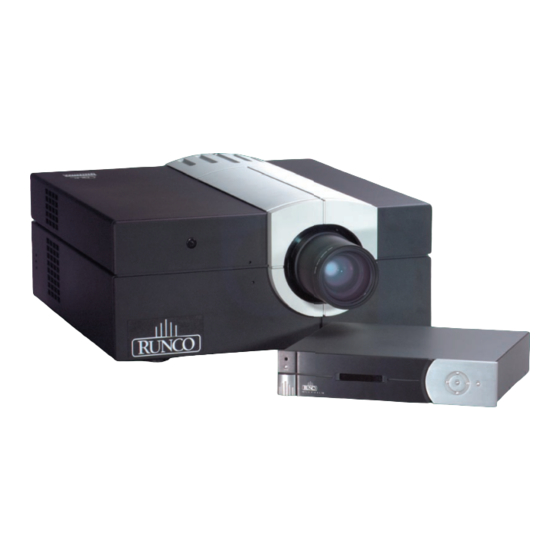
WNER 'S PERATING ANUAL Reflection VX-3c Projector VHD Controller Digital Light Processing Projector & Virtual High Definition Controller With Aspect Ratio Control... -
Page 3: Table Of Contents
TABLE OF CONTENTS Section Contents Page Introduction The Projectors ..........1-1 Components . - Page 4 VHD Controller Manual ..............6-1 Warnings and Safety Precautions .
- Page 5 Modular design for easy servicing. How The Projector Work? The VX-3c can accept data/graphics and video input signals for projection on to front or rear flat screens. High brightness light is generated by an internal 700W Xenon arc lamp, then modulated by three DMD (digital micromirror device) panels that provide digitized red, green or blue color information.
-
Page 6: Components
Included with the VX-3c is an infrared (IR) remote keypad, high-current 13 amp rated line cord, a 9/64” hex socket ball driver, and a VX-3c owner’s manual. Make sure that you have all these items, and note that if you have purchased this projector, a purchaser’s Warranty Registration Card is also included. -
Page 7: Quick Setup
INSTALLATION & SETUP This section explains how to install and set up the projector. If you are familiar with the projector and want to quickly set it up for temporary use, follow the Quick Setup instructions below. For a more complete setup, fol- low the instructions and guides covered in the remaining subsections. -
Page 8: Installation Considerations
INSTALLATION AND SETUP STEP 6! Adjust Image ! ZOOM: With the input image displayed, rotate the textured ring on the lens barrel to increase or decrease the image size (this requires a Zoom zoom lens). If you don’t have a zoom lens or you can’t adjust the image enough, the projector may not be positioned at the proper throw distance for your screen size. -
Page 9: Installation Type
INSTALLATION AND SETUP Installation Type! Choose the installation type which suits your needs: front or rear screen, floor mount or invert- ed mount. Front Screen, Floor Mount Installation ADVANTAGES CONSIDERATIONS Chapter 1 Easy to set up Chapter 4 Shares floor space with audience Chapter 2 Can be moved or changed quickly Chapter 3 Easy to access Front Screen, Inverted Mount (ceiling) Installation... - Page 10 INSTALLATION AND SETUP Figure 2.1. Audience Coverage with Flat Screen NOTE: Lenses for this projector are designed primarily for use with flat screens, but the projec- tor depth-of-field range allows the lens to be focused on curved screens as well. While focus remains sharp in the corners, there may be significant pincushion distortion, primarily at the top of the screen.
- Page 11 INSTALLATION AND SETUP Figure 2.2. Poor Screen Placement Ideal Room Lighting! The high brightness output of this projector is certainly well suited for locations where ambient lighting is less than optimum for projection, yet there are still many simple things you can do to optimize your installation.
- Page 12 INSTALLATION AND SETUP Even with all lighting removed it is still possible that room reflections within the room can slight- ly degrade the image. Light from the projection screen should be absorbed by the ceilings, walls and floors so that it will not be reflected back to the screen. Again, keep reflective surfaces to a minimum.
-
Page 13: Projector Position And Mounting
INSTALLATION AND SETUP Figure 2.4. Screen Locations for Maximum Audience Coverage Projector Position and Mounting Installation type, screen type, and lighting all affect where the projector is positioned. In addition, both throw distance (the distance between the projector and screen) and vertical position (the height of the projector in relation to the screen) must be determined for every new installation. - Page 14 INSTALLATION AND SETUP Vertical & Horizontal Position ! THE VERTICAL POSITION of the projector in relation to the screen also depends on the size of the screen and the lens type. Correct vertical position helps ensure that the image will be rec- tangular in shape rather than keystoned (having non-parallel sides) and that image focus and brightness both remain optimized.
- Page 15 INSTALLATION AND SETUP Figure 2.7. Maximum Vertical Offsets (ZOOM LENSES) NOTES: 1) If you cannot raise or lower the image enough using mechanical vertical offsets, try adjusting V-Position in the Size and Position menu (see 3.6, Adjusting the Image). 2) If the image becomes keystoned or exhibits uneven brightness, the projector may simply be too high or low in relation to the screen.
- Page 16 Figure 2.9. Horizontal and Vertical Tilt Ranges You must use the proper ceiling mount fixture or stacking kit for your projector. For more infor- mation, contact your Runco dealer. 2-10...
-
Page 17: Source Connections
The position of the projector and mirror must be accurately set-if considering this type of installation, call your Runco dealer for assistance. Source Connections The rear panel of the projector provides standard input panels to which you may connect a vari- ety of sources. - Page 18 (such as a 15-pin “D” con- nector for computer sources). Contact your Runco dealer. Connect the SYNC BNC input(s) first. Then connect the red, green and blue source outputs to the RED, GREEN, and BLUE BNCs on the INPUT 1 panel.
- Page 19 INSTALLATION AND SETUP YPbPr Signal (COMPONENT VIDEO)! Connect a YPbPr signal (component video) to INPUT 1 as shown in Figure 2.12. Figure 2.12. Connecting YPbPr Signal NOTES: 1) If, for some reason, the projector fails recognize a YPbPr signal, specify this Color Space option within the Image Settings menu.
- Page 20 INSTALLATION AND SETUP Composite Video! The video decoder input panel provides simultaneous connection of both a composite video source (INPUT 3) and an S-Video source (INPUT 4). If connecting a composite video source, use the Composite BNC connector or the RCA phono jack at -do not use both as inputs.
- Page 21 INSTALLATION AND SETUP S-Video! The video decoder input panel provides simultaneous connection of both a composite video source (INPUT 3) and an S-Video source (INPUT 4). If connecting an S-Video source, use the 4-pin mini DIN connector or the Y and C BNC con- nectors (luma and chroma) at INPUT 4-do not use both as inputs.
- Page 22 INSTALLATION AND SETUP Video Loop Through ! To loop a single incoming video signal input (connected at the video decoder) through to anoth- er projector or display device, use the empty connector(s) adjacent to this same input as described below. Composite Video Loop Through CONNECTIONS: See Figure 2.15.
- Page 23 INSTALLATION AND SETUP S-Video Loop Through CONNECTIONS: See Figure 2.16. From your source, connect an S-video source signal to INPUT 4 using either the 4-pin mini DIN or the 2 adjacent BNCs labeled Y and C. Connect a second cable from whichever INPUT 4 connector is free to one of the S-video inputs of the next display device or projector.
- Page 24 Figure 2.17. Connecting an Extra Video Source to Input 1 Optional Inputs! Optional modules from Runco allow you to increase your total number of inputs and/or accom- modate different signal types, whether analog or digital. Any one of these modules can be installed in the area labeled INPUT 2.
-
Page 25: Power Connection
INSTALLATION AND SETUP Power Connection Plug the projector’s high-current 13-amp rated line cord into the line input socket located in the lower right corner of the rear panel of the projector, then plug the 3-pronged end of the line cord into a grounded AC outlet. -
Page 26: 2.8 Zoom, Focus & Lens Offset
INSTALLATION AND SETUP 2.8 Zoom, Focus & Lens Offset Once the projector is properly set up and producing an image, you are ready to make quick lens adjustments. Zoom! If you have a zoom lens installed, turn the textured ring of the lens barrel to decrease or increase the size of the image at the current throw distance. - Page 27 INSTALLATION AND SETUP Figure 2.19. RS-232 Serial Connection to a Computer RS-422 Ports Some systems can provide RS-422 serial communications (often through a plug-in adapter or external converter) rather than the more common RS-232. RS-422 communication has differen- tial “transmits-and-receives” and is generally better suited for long distances than is RS-232 com- munication.
- Page 28 INSTALLATION AND SETUP Figure 2.20. RS-422 Serial Connection to a Computer WARNING Do not use an RS-422 port unless you are using a computer with RS-422 capability. The voltage levels of this signal can damage incompatible equip- ment. If using multiple projectors! Serial Communications RS-232 NETWORK: To control multiple projectors with a computer/controller having an RS- 232 interface, chain the projectors together by connecting the RS-232 OUT connector of the first...
- Page 29 INSTALLATION AND SETUP RS-422 NETWORK: To control multiple projectors with a computer/controller having an RS- 422 interface, you can chain the projectors together by connecting the RS-422 PORT 2 connec- tor of the first projector (already connected to the computer/controller) to the RS-422 PORT 1 connector of the next projector in the chain.
- Page 30 INSTALLATION AND SETUP l;kjd;flkj;lkasjd;lkjfa;sdff l;kjd;flkj;lkasjd;lkjfa;sdff l;kjd;flkj;lkasjd;lkjfa;sdff ;laskdjf;lieuiodmca:LKs ;laskdjf;lieuiodmca:LKs ;laskdjf;lieuiodmca:LKs eopedjivncfhasp;rpprgm eopedjivncfhasp;rpprgm eopedjivncfhasp;rpprgm oiawoedfpawreoifasjdfl oiawoedfpawreoifasjdfl oiawoedfpawreoifasjdfl Proj 001 Proj 002 Proj 003 l;kjd;flkj;lkasjd;lkjfa;sdff l;kjd;flkj;lkasjd;lkjfa;sdff ;laskdjf;lieuiodmca:LKs l;kjd;flkj;lkasjd;lkjfa;sdff ;laskdjf;lieuiodmca:LKs ;laskdjf;lieuiodmca:LKs eopedjivncfhasp;rpprgm eopedjivncfhasp;rpprgm eopedjivncfhasp;rpprgm oiawoedfpawreoifasjdfl oiawoedfpawreoifasjdfl oiawoedfpawreoifasjdfl Use either or both network cable types RS-422 RS-232 Use either or both...
- Page 31 INSTALLATION AND SETUP Projector Numbers! Each projector can be assigned a unique 3-digit projector number (for example, 001). These num- bers are particularly useful when you are working with multiple linked projectors, enabling you to direct commands to a certain projector rather than always broadcasting to the entire network. For complete information on how to assign projector numbers, see 3.7, Adjusting System Parameters and Advanced Controls.
- Page 32 INSTALLATION AND SETUP Figure 2.24. Independent Keypads and Projectors Remote Keypad! Protocol - IR OR WIRED KEYPAD - The standard IR remote keypad or the optional wired remote can be set to one of two different protocols - “A” or “B”. To hard-wire a protocol to “A” or “B” in either remote, follow Steps 1 through 5: Step 1 Unplug the keypad from the projector (applies to wired remote only).
- Page 33 INSTALLATION AND SETUP ! J1 jumper: For either remote, set between pins 1 and 2 to set as Protocol “A”. Set between pins 2 and 3 to set as Protocol “B”. ! J2 jumper: For either remote, set between pins 2 and 3 as shown; otherwise, the projector will not respond correctly to keypad commands.
- Page 34 INSTALLATION AND SETUP NOTE: If you change any keypad to a new protocol and the projector stops responding, the pro- jector may be set to a conflicting protocol. Use the projector’s built-in keypad to access the Communications menu. Under “Front IR” or “Back IR” or “Wired Keypad”, select the protocol that matches the new protocol of the keypad at hand.
-
Page 35: Overview
OPERATION Overview This section explains how to use the projector once it has been installed. Please read through these pages before using the projector for the first time. An understanding of projector features and how to access them will help you to take full advantage of the capabilities of the projector within min- utes. - Page 36 OPERATION Components / Features! ZOOM- Adjusted manually, the lens barrel of a zoom lens rotates to adjust the size of the image without moving the projector. Minimum and maximum image sizes depend on which zoom lens is installed. FOCUS- Adjusted manually. Focus adjusts the sharpness of the image at the current throw dis- tance.
- Page 37 Consult the rear LCD display for an explana- tion, and see 3.9, Error Conditions. Should the problem persist, contact your Runco dealer. REMOTE WIRED KEYPAD CONNECTOR (3-pin XLR) - For optional tethered remote control of the projector.
-
Page 38: Using The Keypad
OPERATION 3.3 Using the Keypad The keypad appears in two locations: !$Infrared (IR) Remote for wireless control up to 100 feet away !$Wired Remote (optional) tethered to the rear of the projector While each keypad is identical in layout and provides complete control of the projector, you may find one keypad more convenient than another for your specific installation and application. - Page 39 OPERATION Input2 Input 2 Input2 Press to select the source connected to INPUT 2 on the projector (an optional interface). This is the same as entering Input Input 3 Input3 Press Input3 to select the source connected to INPUT 3 on the projector (composite video). This is the same as entering Input Input4...
- Page 40 OPERATION Stby* Stby* hold again (or use ). Or simply press Menu Exit Menu Menu Press to display the Main menu. A list of several options appears for access to specific func- Menu tions, such as Channel Setup or Image Settings. Press again to remove all menus and return Menu to the displayed source.
- Page 41 OPERATION turn the audio and menu display on Mute* turn the audio and menu display off Mute* turn the menu system on OSD* turn the menu system off OSD* Color Color Press Color to adjust the color saturation level, i.e. the amount of color in a video image. Lower settings produce less saturated colors - a setting of "0"...
- Page 42 OPERATION To use a specific projector, enter the 3-digit number assigned to the projector you want to use. Press to select, press to cancel. If you switch to a projector other than the one you Exit Enter are currently using, the checkmark will be deleted. To broadcast to multiple projectors, press then again without entering a projec- Proj...
- Page 43 OPERATION = Red Func = Green Func = Blue Func = Red and Green Func = Green and Blue Func = Red and Blue Func = All colors Func NOTE: Once is pressed (with no OSD present), the projector will not respond to non- Func numeric entry until 2 digits have been entered or until 5 seconds of inactivity have elapsed.
-
Page 44: 3.4 Navigating The Menus
OPERATION 3.4 Navigating the Menus Most of the controls for the projector are accessed from within the projector's menu system. There are several groups of related functions, with each group selectable from the Main menu as shown at right. Press at any time to display the Main menu. - Page 45 OPERATION Figure 3.4. Accessing General Help Topics At the bottom of some menus, a line of 'hint' text also appears. Time-outs ! Whenever there are on-screen menus such as when there is a slidebar, menu, message or test pat- tern displayed, you have limited time in which to make a keypad entry before the graphic disap- pears.
- Page 46 OPERATION Double slidebars - In double slidebars, such as the pixel tracking/pixel phase double slidebar, Adjust with position adjust the top slidebar with H-Position 538 desired. When you have finished with the top V-Position 414 slidebar (whether changed or not), adjust the bottom slidebar with .
- Page 47 OPERATION Figure 3.5. Example of Pull-Down List Or, if you prefer to quickly scroll through a list without first pulling it down, highlight the option and use . Press when the desired choice appears. Enter NOTES: 1) Press to jump between "pages" in an extra long pull-down list. 2) Press while in a pull-down list to cancel any change.
-
Page 48: Using Inputs And Channels
OPERATION NOTE: Press at any time to cancel changes and return to the previously-defined text. Exit Editing Numerical Values ! Enter numbers directly from the keypad in order to specify numbers representing projectors, channels (source setups), switchers, or slots. As each digit is entered, it is displayed and the cursor moves on. - Page 49 OPERATION CHANNEL - A channel is a collection of measurements, locations and settings that tailor a dis- play to your specific needs. Since source types and applications can vary greatly, you will likely want to adjust and define a wide variety of parameters, such as brightness, contrast, tint, size, etc., in order to customize and optimize the display coming from a particular source.
- Page 50 OPERATION USING A CHANNEL: You can normally select a channel at any time by pressing Chan (see right). If you want to prevent a channel from appearing in this list, you must edit the channel as described in Channel Edit later in this section.
- Page 51 OPERATION Copying or Deleting Channels ! TO COPY A CHANNEL, highlight the desired channel in the Channel Setup menu, then press to go to the Channel Copy/Delete submenu. Select "Copy" and press Enter -a new channel Func will be created. It is identical to original, which still remains, but it is identified with the next available number from 01-99.
- Page 52 !"SWITCHER NUMBER: "0" represents the projector itself. This will likely always be the case for the VX-3c. !"SLOT: 1 ( ), 2 (...
-
Page 53: Adjusting The Image
OPERATION !" NEXT CHANNEL: Select this option to see or change Channel Edit settings for the next channel in the Channel Setup list. Adjusting the Image Most options for image adjustments can be accessed through two menus: Size and Position Menu Menu ) and Image Settings (... - Page 54 OPERATION Changes made to the Size and Position menu are applied immediately and are saved when you exit the menu (press Menu Exit Resize Presets Use Resize Presets to quickly display an image in its native resolution (including anamorphic) or to automatically resize an image to fill the screen.
- Page 55 OPERATION order to fill the screen. Non-HDTV (16:9) anamorphic images, common on DVDs, will be stretched vertically. With the exception of HDTV (16:9), the “Full Screen” setting produces an aspect ratio that is either almost or exactly 4:3. ! SELECT “ANAMORPHIC” to display an entire non-HDTV “wide screen”...
- Page 56 OPERATION Pixel Phase (SHORT CUT: Press Pixel and adjust the bottom slidebar.) Pixel phase adjusts the phase of the pixel sampling clock relative to the incoming signal. It is used primarily for adjusting RGB inputs. NOTE: Adjust pixel phase after pixel tracking is properly set. Adjust pixel phase when the image (usually from an RGB source) shows shimmer or “noise”.
- Page 57 OPERATION This option moves the picture up and down. NOTE: The value shown represents where the approximate center of the image lies in relation to the total number of pixels available vertically. This varies widely according to the signal- watch the image while adjusting. Blanking: Top, Bottom, Left or Right Blanking This submenu blanks (turns to black) the top, bottom, left, or right...
- Page 58 OPERATION Color (SHORT CUT: Press and adjust the slidebar.) Color “Color” adjusts color saturation level, or the amount of color in a video image. For example, setting Color to “0” produces a black and white image. If Color is set too high, the color levels in the picture will be over-powering and unrealistic.
- Page 59 OPERATION The current color space appears in the Image Settings menu. Press to select a different Enter option: ! Select RGB unless you are using component video at INPUT 1 or 2. ! Select YPbPr (video) if you are using a standard definition televised signal (SDTV) ! Select YPbPr (HDTV) if you are using a high definition decoder (HDTV).
-
Page 60: 3.7 Adjusting System Parameters And Advanced Controls
OPERATION Figure 3.14. Selected Gamma Curves 3.7 Adjusting System Parameters and Advanced Controls Use the Communications, Preferences and Status menus to display and/or alter overall system parameters rather than those that affect a specific source or channel. Use the Advanced menu whenever you need to work with or replace the lamp, select a test pat- tern, define a new color temperature, or access lesser-used image control settings intended for experienced users. - Page 61 Keep at “A OR B” unless you are sure of the current IR keypad protocol. NOTES: 1) The IR remote keypad for this projector is set at Runco to “Protocol A”. See 2.10, Keypad Protocols and Conversion for information about changing the keypad protocol. 2) A key press from a conflicting protocol will cause a single yellow flash on the Status LED located in the lower right corner of the rear projector panel.
- Page 62 OPERATION to safely change its own protocol: 1. Select the A or B option. This will ensure that once your keypad is manually changed (see Step 2), it will still be recognized by the projector. 2. Unplug the keypad and change the protocol in the keypad as desired. Do this either by entering the short-cut software command or by hard-wiring the keypad as described in 2.10, Keypad Protocols and Conversion.
- Page 63 OPERATION Figure 3.16. Preferences Menu Image Orientation Choose from Front, Rear, Inverted Front, Inverted Rear according to your installation. If the setting is incorrect, the image will be reversed and/or upside down. See 2.6, Operating Orientation for an illustrated explanation. Keystone Non-functional in this version of software.
- Page 64 OPERATION Auto Power Up Enter a checkmark to enable the projector to automatically power up after losing power due to unplugging or a power failure. Note that unsaved display adjustments may be lost. Video Termination Enter a checkmark to terminate the video inputs 3 and 4 (75 W). The input should be terminat- ed unless the signal loops through (continues) to another * For all single free-standing projectors projector or display device, in which case only the last...
- Page 65 OPERATION TEST PATTERNS - Select this option to use a pull-down list of all avail- able internal test patterns. Test NOTE: For quicker access from your presentation, use the key to cycle through the patterns. At the last pattern, press to return to your Test presentation-or press...
- Page 66 OPERATION BLACKLEVELS AND DRIVES - To check your image and adjust these controls: 1. Make sure overall Contrast and Brightness are both set to near 50. NOTE: Not required for “Auto” adjustment. Cont = 50 (approx.) !"" = 50 (approx.) Brite 2.
- Page 67 OPERATION Odd Pixel Adjustment NOTE: For sources with Color Space set to RGB only. When using certain RGB sources with static images, you may need to adjust the normal gain or offset of odd pixels in relation to even in order to smooth out very narrow (1-pixel wide) checks or vertical stripes.
- Page 68 OPERATION Figure 3.20. Advanced Color Temperature Menu However, if you require extra color temperatures, you can also add up to five custom color tem- peratures-four "User" and one "Interpolated"-by defining them within the Advanced Color Temperature menu (each defaults to 6500K until then). Any "User" or "Interpolated" tempera- ture created here is immediately applied, or it can be selected at any time from the Image Settings menu as usual, regardless of your source or channel.
- Page 69 OPERATION COPY FROM - Use this option to replace the currently selected "User" color temperature setup with that of another. This function can be particularly useful for creating a starting point for a new "User" color or for accessing an unaltered factory default. It is disabled for all color temperatures except "User".
- Page 70 OPERATION Advanced Image Settings DECODER LUMA DELAY - This option affects any incoming composite or S-video sig- nal, delaying the luma signal (intensity) in rela- tion to the chroma (color). In the image, increasing the luma delay will move luma (seen as a shadow where colors overlap) to the right slightly, with colors remaining in place.
- Page 71 OPERATION LAMP HOURS shows the number of hours logged on the current lamp. Whenever you record a new lamp serial number, this value automatically resets to "0", where it begins to log time for the new lamp. NOTE: Read-only. This information also appears in the Status menu. LAMP S/N is the serial number recorded for the current lamp.
- Page 72 OPERATION power level you wish to maintain. See "Power" below. POWER - The number shown here indicates how many watts are applied to the lamp. Set from 450-700 watts as desired, keeping in mind that lower power levels produce dimmer images. When in "Power"...
- Page 73 OPERATION Use CHANGE LAMP to record Lamp the serial number for a newly Lamp Hours 1999 Lamp S/N 1234 installed lamp. Lamp Message Lamp Limit 2000 In the Lamp S/N window, use the Lamp Mode Power Lamp History Power number text entry keys to record New S/N entry Intensity 2750...
-
Page 74: Using Multiple Projectors
OPERATION Figure 3.26. Status Menu (SAMPLE) Using Multiple Projectors When working with multiple projectors, you may want to use the RS-232 or RS-422 serial ports to chain the projectors together in a network that you control from either a keypad or a comput- er/controller (see 2.9, Serial Port Connections). -
Page 75: Error Conditions
OPERATION Broadcasting to All Projectors! On the IR remote or wired keypad, press to display the projector box. Press again without entering a number - the keypad commands will now affect all projectors. Make certain that only one projector has its "Broadcast Keys" option selected (checked) - the remaining projectors should have the option unchecked and their keypads disabled (do this in Preferences menu). - Page 76 Errors, above). Try resetting the projector by powering it off and on again, cooling when neces- sary. Consult Table 1 and contact your Runco dealer if the problem persists. The specific pattern of flashing indicates the 2-digit code identifying the type of problem encountered-the number of yellow flashes represents the first digit and the number of red flash- es indicates the second digit.
- Page 77 Fan #4 failed (side fan, front—connects to J39 on ICM) Low voltage power supply failed to turn on MOTOR CONTROL MODULE ( not in the VX-3c) Problem communicating with MCM INTERCONNECT OR CHASSIS I.D. Unable to access EEPROM on the ICM...
-
Page 78: Warnings And Guidelines
Do not place the projector on an unstable cart, stand or table. If the projector is to be ceiling mounted, only use a Runco-approved ceiling mount fixture. A projector and cart combination should be used with care. Sudden stops, excessive force, and uneven surfaces may cause the projector and cart combination to over- turn. - Page 79 Operate the projector at the specified voltage only. Do not overload power outlets and extension cords as this can result in fire or shock hazards. Runco recommends a dedicated AC circuit for the projector itself.
-
Page 80: Cleaning
Do not attempt to service the projector yourself. All servicing must be performed by a qualified Runco service technician. If replacement parts are required, it is important that only Runco- approved parts are used. Other parts may result in fire, electric shock or risk of personal injury. -
Page 81: Replacing Keypad Batteries
Advanced menu) and the Status menu. In the Status menu, do not confuse “Lamp Hours” with “Lamp Counter”, which indicates the number of hours logged during the ‘rental period’, in a situation where the VX-3c is to be rented for various functions. In a permanent install, this would be of no consequence. -
Page 82: Replacing The Lens
MAINTENANCE Replacing The Lens A variety of lenses are available to accommodate different throw distances and specific types of installations. See page 5-1 for details. To change a lens, follow the steps below. NOTES: 1) You will need a 9/64”(3mm or 3.5mm) hex socket ball driver (supplied with projec- tor) or allen wrench for this procedure. - Page 83 MAINTENANCE !IF ZOOM LENS: Access to the 3 lens mount screws is likely blocked by the toothed zoom ring in front of it. First rotate the zoom ring by hand until its 3 access holes align with the screws, then insert the hex socket ball driver through the holes to loosen the screws-do not remove.
- Page 84 MAINTENANCE STEP 4!"Pull lens assembly out ! See Figure 4.13. Carefully pull the lens assembly straight out of the projector and set aside. Figure 4.13. Remove lens assembly STEP 5! Install new lens assembly ! IMPORTANT: Remove the rear (smallest) lens cap from the new lens.
-
Page 85: 4.5 Troubleshooting
4.5 Troubleshooting If the projector appears not to be operating properly, note the symptoms present and use the fol- lowing guide to assist you. If you cannot resolve the problems yourself, contact your Runco dealer for assistance. NOTE: Always check the LCD status window at the rear of the projector for initial information about a problem. - Page 86 MAINTENANCE steady red? This indicates an internal system error that may prevent the projector from operat- ing. If the problem persists contact a qualified Runco service technician. Symptom! The projector does not respond to the infrared remote keypad... CAUSE / REMEDY: 1.
- Page 87 MAINTENANCE 6. The location of the audience with respect to the screen may not be ideal. Make sure the audi- ence is within the viewing angle set by the projector and screen position, and the screen type. 7. The source may be double terminated. Ensure the source is terminated only once. 8.
- Page 88 MAINTENANCE Symptom!Colors in the display are inaccurate… CAUSE / REMEDY: 1. The color, tint, gamma, color space and/or color temperature settings may require adjustment. Review all settings, and refer to 3.6, Adjusting the Image and 3.7, Adjusting System Parameters and Advanced Controls. Symptom! The display is not rectangular…...
-
Page 89: Specifications
Specifications Specifications NOTE: Due to continuing research, specifications are subject to change without notice. Display! Resolution Pixel format (H x V) on 3 DMD panels 1024 X 768 (XGA) Maximum digitizing sample rate 160 Mega samples per second Video luminance bandwidth 5.5 MHz Brightness Vista = 3000 ANSI lumens, typical... - Page 90 SPECIFICATIONS Analog RGB and YPbPr (INTERLACED OR PROGRESSIVE SCAN FORMAT) Horizontal frequency range 15 - 120 kHz * Vertical frequency range ** 24 -120 Hz Pixel clock rate 10 - 160 MHz Signal format Analog RGB or YPbPr Input levels R,B,G,Y - with sync 1.0Vp-p ±2 dB R,G,B - without sync...
- Page 91 SPECIFICATIONS Wired Control Input Optional wired keypad 3-pin XLR connector Input level High 2.0V min., Low 0.7V max. Power Requirements! Voltage range (auto switching) 100 to 240 VAC continuous Line frequency 50 - 60 Hz nominal Max. inrush current 60 amps Max.
- Page 92 SPECIFICATIONS ESD Susceptibility: EN61000-4-2 Level 4 Radiated Susceptibility: EN61000-4-3 Level 3 EFT/Burst: EN6100-4-4 Level 4 Input transcient protection: EN61000-4-5 Level 3 Operating Environment! Temperature 0°C to 35°C (32°F to 95°F) Humidity (non-condensing) 20% to 80% Altitude 0 - 3000 meters Standard Components! IR (infrared) Remote Keypad - includes batteries High current 13 amp rated line cord...
-
Page 93: Vhd Controller Manual
International copyright treaties, as well as other intellectual property laws and treaties. IMPORTANT - READ CAREFULLY: This Runco License Agreement is a legal agreement between you (either an individual or a single entity) and Runco International for the Runco software product installed within the VHD Controller. -
Page 94: Warnings And Safety Precautions
Warnings and Safety Precaution CAUTION: To turn off main power, be sure to remove the plug from power outlet. The power outlet socket should be installed as near to the equipment as possible, and should be easily accessible. REMARQUE: Pour mettre l’appareil hors circut, s’assurer de retirer la fiche de la prise d’alimenta- tion. -
Page 95: Safety Tips
Runco dealer for a replacement cord. • Do not remove the cover of the unit for any reason. If any problems arise with the unit, please contact a Runco dealer or Runco International for service. Removing the cover will void the warranty. -
Page 96: Introduction
Congratulations on your purchase of the VHD Controller! This processor is designed to work with the VX-3c Projector and will provide full aspect ratio control as well as greatly enhanced picture quality. For example, DLP projectors were not initially designed to be used on wide aspect-ratio screens (16:9 or 1.85:1). -
Page 97: Front And Rear Panel Description
FRONT AND REAR PANEL DESCRIPTIONS Front Panel V H D C O N T R O L L E R IR RECEIVER Receives the IR commands from the remote control. MENU BUTTON The MENU button brings up the main adjustment menu. After making adjustments, the MENU button will bring you back to the sub-menu, then the main menu. -
Page 98: Rear Panel Description
This is the main output of the VHD Controller. The RGB Signal goes directly to the VX-3c projector; If component is used through the pass-through, then only the R (Pr), G(Y) and B(Pb) jacks will be active. Individually, the jacks are: V=vertical sync, H=horizontal sync, B=Blue, G=Green, R=Red. - Page 99 FRONT AND REAR PANEL DESCRIPTIONS 10. RS-232 Output The output of this jack must be connected to the PC Control input of the VX-3c Projector. This communication will allow the controller and projector to be turned on simultaneously by turning on just the VHD Controller.
-
Page 100: Remote Control Description
FRONT AND REAR PANEL DESCRIPTIONS Remote Control Description A. LED Lights when a button is pressed indicating IR output. B. POWER BUTTON Turns the unit on. The MAIN POWER switch on the rear of the unit must be on first for this button to be active. UP BUTTON When no menu is present on-screen, this button will toggle you through the different aspect ratios. -
Page 101: Quick Set-Up Guide
Quick Set-up Guide Connection Examples U N CO 12v Fuse S-VIDEO RS-232 IN Pass-through RS-232 OUT COMPOSITE Mask Screen Projector VX-3c Projector VCR, Laser DVD Player disc player, camcorders Phast or Crestron Computer or Sattelite DTV decoder receiver or SVHS player... -
Page 102: Getting Started
To get started using your VHD Controller and projector, follow these simple steps: Ensure all sources that you are using are properly connected to the VHD Controller. This is something your Runco dealer has probably already done for you; if not, please refer to the ‘Connection Examples’ and the owners manuals of each appropriate source as necessary. -
Page 103: Overall Functional Description
480p signal is scaled to appropriate resolution, and then output to the projector. It is Runco’s high-quality scaling process as well as its de-interlacing that provides the clean, resolved image that you see from your VX-3c projector. It is also how the processor can provide aspect ratio control. -
Page 104: Menu Description
MENU DESCRIPTION AND NAVIGATION Main Menu MAIN MENU > COMPOSITE ADJUST S-VIDEO Source selection and COMPONENT picture quality adjustments PASS-THROUGH ASPECT RATIO PASS-THROUGH SETUP Aspect ratio selection Sets masking parameters for screens with masking capabilities. The main menu (shown above) includes two sections: Source Selection/ Picture quality adjustments and Functional adjustments. - Page 105 MENU DESCRIPTION AND NAVIGATION Aspect Ratio allows selection of one of the three aspect ratios provided by the processor. You have two options for selecting an aspect ratio: First, highlight ASPECT RATIO on the main menu, then press ENTER. Then select the desired aspect ratio, and again press ENTER.
- Page 106 MENU DESCRIPTION AND NAVIGATION After pressing ENTER, the picture quality menu will appear (the menu to the right of the main menu above). To adjust a certain function, highlight it with the or DOWN buttons, and press ENTER. The following will then appear on-screen (we’ll use COLOR as an example): COMPOSITE COLOR:...
- Page 107 MENU DESCRIPTION AND NAVIGATION • SHARPNESS This controls the ‘high-frequency’ detail of the image. The more sharpness is increased, the more detail is added into the picture. However, if it is increased too much, it will also increase ‘noise’ in the picture as well as other types of artifacts. This may be set to personal preference;...
-
Page 108: Aspect Ratios
Obviously, watching a movie like this does not lend itself to a truly cinematic experi- ence! This is why Runco invented the first-ever multiple aspect-ratio projection sys- tem back in 1991, so true movie-lovers can watch actual widescreen (letterbox) movies on a WIDESCREEN! A WIDESCREEN can be a number of aspect ratios;... - Page 109 ASPECT RATIOS Active image area Blanked (cut off) (Actual screen area) areas As you can see, our screen in this example is a 1.85:1 ratio. The dashed lines show the area that we ‘blanked’. If you recall, watching a letterbox movie on a 4:3 screen gave us black bars;...
-
Page 110: Dimensions
DIMENSIONS Front Panel 17.45" 3.5" V H D C O N T R O L L E R Rear Panel 17" U N CO 3.5" 12v Fuse S-VIDEO RS-232 IN Pass-through RS-232 OUT COMPOSITE Mask Screen 17" 16" 17.45" Side 3.5"... -
Page 111: Rs-232 Protocol
RS-232 PROTOCOL 9600 Baud 8 bits No parity 1 Stop bit ASCII RxD of the PC or TxD of the VHD is on pin2 TxD of the PC or RxD of the VHD is on pin3 Gnd is pin 5 RTS of the PC or CTS of the VHD is on pin7 (not used) CTS of the PC or RTS of the VHD in on pin8 (not used) Command format <input><aspect ratio>... -
Page 112: Specifications
SPECIFICATIONS Inputs: (1) Component, (1) S-video, (1) Composite, (1) Pass-through Input standards: NTSC (PAL, NTSC export version) Output formats: 1024 x 575 (anamorphic), 768 x 575 (wide screens), 1024 x 768 (4:3 screens) Bandwidth: Video inputs: 0-5.5 Mhz Pass-through: 100 Mhz Power input: 120V (220V export model), 50/60 Hz Power... -
Page 113: Glossary
Appendix A Glossary This appendix defines the specific terms used in this manual as they apply to this projector. Also included are other general terms commonly used in the projection industry. Active Line Time! The time, inside one horizontal scan line, during which video is generated. Ambient Light Rejection! The ability of a screen to reflect ambient light in a direction away from the "line of best viewing". - Page 114 GLOSSARY Checkbox! A menu item that indicates whether an option is currently in effect (checked) or not (unchecked). Color Shift! A change in the color of a white field across an image (white field uniformity). Color Temperature! The coloration (reddish, white, bluish, greenish, etc.) of white in an image, measured using the Kelvin (degrees K) temperature scale.
- Page 115 GLOSSARY a 10 gain screen appears 10 times brighter than it would if reflected off a matte white wall. Curved screens usually have larger gain than flat screens. Help Screen! A display of help information regarding the current task or presentation. Horizontal Frequency! The frequency at which scan lines are generated, which varies amongst sources.
- Page 116 GLOSSARY Menu! A list of selectable options displayed on the screen. NTSC Video! A video output format of some video tape and disk players. There are two types of NTSC (National Television Standards Committee) video: NTSC 3.58 and NTSC 4.43. NTSC 3.58 is used primarily in North America and Japan. NTSC 4.43 is less commonly used.
- Page 117 GLOSSARY RGB Video! The video output (analog or digital) of most computers. Analog RGB video can have 3, 4, or 5 wires - one each for red, green, and blue, and either none, one or two for sync. For three-wire RGB, the green wire usually provides sync. (See TTL Video). RS-232! A common asynchronous data transmission standard recommended by the Electronics Industries Association (EIA).
- Page 118 GLOSSARY Throw Distance! The distance between the front feet of the projector and the screen. Also called "Projector-to-Screen Distance". Always use the correct throw distance formula to calcu- late the proper throw distance (±5%) required for your lens. Tint! Balance of red-to-green necessary for realistic representation of NTSC signals. Variable Scan! The ability of a projector to synchronize to inputs with frequencies within a specified range.
-
Page 119: Keypad Reference
Appendix B KEYPAD REFERENCE Figure B-1. Keypad... -
Page 120: Menu Tree
Appendix C Menu Tree... - Page 121 MENU TREE...
-
Page 122: Throw Distance
Appendix D Throw Distance Always consult this Appendix when planning a projector installation. See also 2.3, Projector Position and Mounting. Calculating Throw Distance Correct throw distance depends on the screen size and lens present-the larger the image needed, the greater the distance you must allow between the lens and screen. Once you know the screen size and lens type present, you can calculate the precise throw distance you require by using the appropriate formula as found in this appendix. - Page 123 THROW DISTANCE...
- Page 124 THROW DISTANCE...
- Page 125 THROW DISTANCE...
- Page 126 THROW DISTANCE...
- Page 127 THROW DISTANCE...
- Page 129 RUMA-003300 rev 9-00 2900 Faber Street Union City, CA 94587 510-324-7777 Fax: 510-324-9300...
Need help?
Do you have a question about the Reflection VX-3c and is the answer not in the manual?
Questions and answers