Table of Contents
Advertisement
Quick Links
See also:
User Manual
Advertisement
Table of Contents

Related Manuals for OpenEye OE2-E12016


Summary of Contents for OpenEye OE2-E12016
-
Page 1: Digital Video Recorder
E-Series Digital Video Recorder User Manual OE2-E12016 model no. model no. OE2-E12008 OE2-E12004 Please carefully read these instructions before using this product. Save this manual for future use. - Page 3 (including without limitation, damages for loss of business profits, business interruption or loss of business information), even if OPENEYE has been advised of the possibility of such damages and whether in an action or contract or tort, including negligence.
-
Page 4: Important Safeguards
Object and Liquid Entry Points – Never insert foreign objects into the DVR, other than the media types approved by OpenEye, as they may touch dangerous voltage points or short-out parts that could result in a fire or electrical shock. -
Page 5: Notes On Handling
When the unit exhibits a distinct change in performance – this indicates a need for service. Servicing – Do not attempt to service this product unless instructed to by an OpenEye engineer. Opening or removing covers may expose the user to dangerous voltage or other hazards. Refer all servicing to qualified personnel. -
Page 6: Notes On Moisture Condensation
NOTES ON MOISTURE CONDENSATION Moisture condensation could damage the DVR. Read the following information carefully. Moisture condensation might occur under the following circumstances: • When this product is brought directly from a cool location to a warm location. • When this product is moved to a hot and humid location from a cool location. •... -
Page 7: Explanation Of Graphical Symbols
EXPLANATION OF GRAPHICAL SYMBOLS The lightning flash with arrowhead symbol, within an equilateral triangle, is intended to alert the user to the presence of un-insulated "dangerous voltage" within the product enclosure that may be of sufficient magnitude to constitute a risk of electric shock to persons. -
Page 8: Standard Warranty
Standard Warranty OpenEye warrants all new products to be free from defects in workmanship and material under normal use for a period of two years after the date of purchase. Any defective product that falls under this warranty will, at OpenEye's discretion, be repaired or replaced at no additional charge. -
Page 9: Table Of Contents
Table of Contents INTRODUCTION ............................13 Product Description ..........................13 Features ..............................14 USB Flash Drive Approved List ......................14 Quick Start Guide ........................... 15 INSTALLATION ............................17 Front Panel Controls ..........................17 Rear Panel Connectors .......................... 18 4 Channel............................18 8 Channel............................ - Page 10 Quick Record Setup ........................... 32 Motion/Event SETUP ......................... 33 Input Setup ............................ 33 Sensor Setup ..........................33 Action Setup ..........................34 EA (Emergency Agent) ......................... 34 Motion Detection Recording ........................35 Network ..............................36 Network Setup ........................... 36 Enabling Free DDNS ........................36 Serial Setup ............................
- Page 11 Access Remote E-Series DVR ....................... 52 Connecting to Multiple DVRs ......................52 Using the Remote Software ........................52 Setting the Time and Date ......................... 52 Display Screen ........................... 53 Camera View..........................54 Screen Division Buttons ........................ 55 Setup Overview ..........................56 Setup Screen Overview ........................
- Page 12 NOTES:...
-
Page 13: Introduction
All OpenEye DVRs come with free RADIUS remote management and viewing software allowing you to connect to any number of DVRs from virtually anywhere using your PC or laptop. OpenEye’s suite of applications allow you to remotely manage DVR settings and permissions, view live virtual multiplexed video from multiple DVRs on multiple displays, monitor alarm and sensor events remotely, create custom maps of facilities, and search or backup recorded video. -
Page 14: Features
FEATURES The OpenEye E-Series DVRs include the following features: • Up to 16 Composite Video Input Connectors • Compatible with Color (NTSC or PAL) and B&W Video Sources • Multiple Search Methods (Date/Time, Calendar, Event) • Records 120 NTSC Pictures Per Second (100 PAL Pictures Per Second) •... -
Page 15: Quick Start Guide
QUICK START GUIDE Turn on the DVR. Note See the Turning on the DVR section for more details. Log in -- Use the number buttons to enter the password when prompted – By default the password is <none> – Press the ENT Button. - Page 16 NOTES:...
-
Page 17: Installation
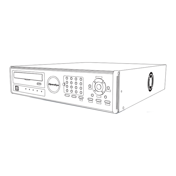
INSTALLATION FRONT PANEL CONTROLS Arrow Buttons DVD Drive Numeric Keypad* Live Display USB Ports LED Lights Rotate Setup Menu • Power Backup Menu Lock (logout) • HDD • Record Search Mode • Network • Fan *The numeric keypad layout differs on the 4 and 8 Channel models 27717AN... -
Page 18: Rear Panel Connectors
REAR PANEL CONNECTORS The rear panel of the DVR contains virtually all of the connectors you will be using. The diagram below outlines the location and description of each connector: 4 CHANNEL Sensor Input Relay Output Video Out Ports RS485 (PTZ) Connection Video In Ports AC Power Input Spot Monitor Outputs... -
Page 19: Channel
8 CHANNEL Sensor Input Relay Output Video Out Ports RS485 (PTZ) Connection Video In Ports AC Power Input Spot Monitor Outputs Power Switch Audio Input / Output VGA Output Network Port RS-232 Input 16 CHANNEL Video Out Ports Primary and Spot Monitor Outputs RS485 (PTZ) Connection Video In Ports S-Video Output... -
Page 20: Remote Control
REMOTE CONTROL Record Toggle ID Select* PTZ Controls Log Off (Lock) Arrow Arrow / Panorama Arrow Arrow / SMART Fast Forward Play Rewind Pause *The ID Select Button allows the user to use one remote control for several DVRs. -
Page 21: Connection Guide
CONNECTION GUIDE CONNECTING THE MONITOR There are three available monitor outputs on the E-Series DVR. • Composite Monitor output for CCTV monitor – BNC (Marked MAIN) • VGA output for VGA monitor – Mini-Sub D15 • S-Video output – Mini-Din 4 (16 Channel only) VIDEO INPUTS AND LOOPING OUTPUTS The E-Series DVR comes with up to 16 BNC video inputs on the rear of its chassis. -
Page 22: Connecting To A Sensor Input
CONNECTING TO A SENSOR INPUT To make connections on the Alarm Connector Strip, remove the connector and use a mini flat-head screwdriver (to open the connection. Insert the wire into the hole and tighten with the screwdriver. To disconnect the wire loosen the screw (counter- clockwise) and pull the wire out. -
Page 23: Setup
SETUP SETUP MENUS SYSTEM SYSTEM SETUP DISK MANAGEMENT USER MANAGEMENT CONFIGURATION SHUTDOWN Use the setup menus to configure all of the DVR settings, schedule recording, networking and shutdown. Press SETUP on the front of the DVR or remote control to enter the setup menus and log in. See the Quick Start Guide section if entering setup for the first time. -
Page 24: System
SYSTEM SYSTEM SETUP SYSTEM SETUP VIDEO FORMAT NTSC LANGUAGE ENGLISH SYSTEM ID DATE FORMAT MM-DD-YYYY DATE 11/06/2006 TIME 10:44:48 TIME ZONE GMT-08:00.. USE DST KEYPAD BEEP AUTO LOG OFF SAVE CANCEL To enter System Setup, press SETUP on the front of the DVR and press ENT to select System Setup. Use the arrow buttons on the front panel of the DVR or the remote control to navigate the display. -
Page 25: Disk Management
DISK MANAGEMENT Format FORMAT – Shows installed Hard Disk Drives and the status of other attached storage devices. To format a Hard Drive use the arrow keys to select the appropriate device and press ENT. Select OK to confirm formatting and press ENT. To format a USB device use the arrow keys to select USB FORMAT and press ENT. -
Page 26: Smart Check
SMART Check SMART CHECK – (Self Monitoring Analysis & Reporting Technology) Enable SMART Check to detect signs of HDD failure. Select SMART ENABLE and press ENT to ENABLE or DISABLE. Set a check interval between 1 and 24 HOURS. Define a temperature threshold and select Celsius or Fahrenheit. -
Page 27: Client
Client Use the Client menu to manage users that access the E120 remotely. Remote users must be defined on this page. Only the users defined here can access the DVR remotely. Add up to 18 users in addition to the two Admin users. To add a new user: Select a LOGIN ID and press ENT. -
Page 28: Camera
CAMERA CAMERA SETUP CH –Camera Channels (on 16 channels DVRs, select CAMERA SETUP - CAMERA 9CH-16CH to display additional channels) NAME ENABLE HIDDEN ADJUST NAME – Use the on-screen keyboard to enter a camera name [user defined] ENABLE – ON/OFF HIDDEN –... -
Page 29: Spot /Sequence Setup
SPOT /SEQUENCE SETUP SPOT SETUP SEQUENCE – ON/OFF [sequences through selected cameras]. CAMERA SETUP - SPOT / SEQUENCE CAMERA – Select cameras to include in sequence. SPOT SEQUENCE CAMERA INTERVAL CURRENT INTERVAL – 1 ~ 256 seconds [Set the sequence interval 2 SEC CAM 1 time]. -
Page 30: Record
RECORD RECORD SETUP Use RECORD SETUP to configure the recording schedule and frame capture rate. In SCHEDULE SETUP, users can define the recording schedules: • DAY • NIGHT • WEEKEND Frame Setup Configure the PPS for each schedule – Day > Night > Weekend. -
Page 31: Audio Setup
Audio Setup Specify volume level and audio settings for recording according to RECORD SETUP - AUDIO preset schedules and live or search mode. DISABLE Select ENABLE/DISABLE for each schedule mode. NIGHT DISABLE WEEKEND DISABLE Select ENABLE/DISABLE for live/search mode. LIVE DISABLE SEARCH DISABLE... -
Page 32: Quick Record Setup
QUICK RECORD SETUP Quick Record Setup allows you to define global recording settings for an easy and custom recording schedule on the DVR. GLOBAL RESOLUTION – 352 x240 / 704 × 240 / 704 × 480. MOTION/CONTINUOUS – Motion / Continuous. AVERAGE DAYS TO RECORD –... -
Page 33: Motion/Event Setup
MOTION/EVENT SETUP Motion / Event Setup has four sections; Input, Sensor, Action, and EA (Emergency Agent). When and event comes in (Input) the DVR records the image according to its settings (Camera Setup) and triggers an alarm (Action). Input Setup CH –... -
Page 34: Action Setup
Action Setup CH – Channels 1~8 / Channels 9~16 MOTION/EVENT SETUP - ACTION ALARM – 1~4 / OFF [Associate an alarm relay with the ALARM DELAY DURATION PRESET camera]. DELAY – 0~100 Seconds [The number of seconds after an event before the image popup displays]. DURATION –... -
Page 35: Motion Detection Recording
MOTION DETECTION RECORDING To record data only when motion is detected: Press SETUP on the front of the DVR or remote control and log in. Select RECORD > EVENT SETUP. Set MOTION to ON. Set the motion Level. [NORMAL > HIGH > HIGHEST > LOW]. -
Page 36: Network
NETWORK NETWORK SETUP Configure network settings. DHCP Select – System gets IP address from DHCP server. Clear – User must manually define a static IP address. Contact the network administrator for this information. HOST NAME – Name current network host. IP ADDRESS –... -
Page 37: Serial Setup
SERIAL SETUP Configure connected serial devices. SERIAL TYPE – Set External Controller or None. MODEL – If External Controller is enabled, select the model from the list. PORT – Define port setting. CLIENT SETUP Configure general remote access REMOTE PORT – Use this port number when configuring NETWORK SETUP - CLIENT remote access software. -
Page 38: E-Mail Setup
E-MAIL SETUP The DVR can send an email notification to up to six defined e-mail addresses when an event occurs. E-MAIL SERVER – DVR/SMTP [Configure the DVR to use EMAIL SERVER SETUP selected e-mail server.] MAIL SERVER SMTP SERVER SCHEDULE – ON/OFF [Enable to send e-mail notifications USER NAME userName only for events that occur within a specified range of time.]... -
Page 39: Information
INFORMATION SYSTEM LOG VIEW Displays system log information. STATUS VIEW Displays status screens for: STATUS VIEW STATUS VIEW STATUS DISK STATUS AUDIO CONTENT STATUS RECORD RECORDING START 07/06/07 12:55:47 RECORDING END 07/11/06 13:05:00 DISK CAPACITY 249GB USED SPACE 533MB (0%) AVAILABLE SPACE 249GB (100%) HDD OVERWRITE... - Page 40 Notes:...
-
Page 41: Operation
OPERATION INSTANT RECORDING To activate Instant Recording on the DVR: Press the button with the red dot on the front panel of the DVR or remote control. Select OK using the arrow buttons. Press the ENT button. Near the top of the screen the words ‘INSTANT RECORD’ will be visible. Press EXIT or the Instant Record button again to disable Instant Recording. -
Page 42: Search Methods
SEARCH METHODS Note When DVD-RW is selected as the target media, only Quick Search, Go To First Recorded Data and Go To Last Recorded Data Search options are available. Quick Search Users can select a specific date and time of recorded data to RECORD LIST SEARCH search. -
Page 43: Search Details
SEARCH DETAILS In Search Mode users can access the Popup Menu for extended options; see the Popup Menu section. SEARCH POPUP MENU Use to access display options in Search Mode. Press ENTER to highlight a channel box. POPUP MENU 1:1 Use the arrow keys to select the desired channel. -
Page 44: Monitoring
MONITORING SELECT CHANNEL • Use the number keys on the front of the DVR or remote control to select specific channels for full screen display. (ex. Press 1 to display channel 1) • Press the LIVE key to change the display mode. Display switches in the following order when the LIVE key is pressed successively. -
Page 45: Backup
Create a mirrored backup of recorded data on a connected USB external hard drive. Caution OpenEye recommends the use of hard drives only; the use of flash drives is not recommended for auto backup. Press BACKUP on the front panel or remote control and log in. -
Page 46: Using The Backup Viewer
USING THE BACKUP VIEWER Play recorded video on a PC using Backup Viewer, the proprietary media player included with every backup file. CONTROLLING BACKUP VIEWER Stop Back Play Forward Play Previous Frame Next Frame Speed Zoom Brightness Contrast... -
Page 47: Viewing Backed Up Video
Firmware is released occasionally that may contain new features and/or updates. Download the latest firmware and extract the ZIP file contents to a CD, DVD or USB Device. Visit openeye.net or contact Tech Support for the latest firmware. The E-Series firmware can also be upgraded using the remote software. See the remote software section. -
Page 48: Save Settings
SAVE SETTINGS Use the System Configuration setup menu to export and import saved or factory default system profiles. EXPORT SETTINGS Press SETUP on the front of the DVR or remote control to log in. Select SYSTEM > CONFIGURATION. Select EXPORT and press ENT on the front of the DVR. Select TARGET to define the type of media (DVD-RW, USB). -
Page 49: Ptz Camera Control
PTZ CAMERA CONTROL SPEED SETUP – 1~8 [Set the speed that PTZ cameras move.] PTZ SETUP CH1 PRESET SETUP – Move/Set [Create preset PTZ camera SPEED SETUP positions.] PRESET SETUP PRESET TOUR – [Create a tour of preset PTZ camera positions.] PRESET TOUR PATTERN SETUP –... -
Page 50: Ptz Compatibility List
PTZ COMPATIBILITY LIST The OpenEye E-Series DVRs are compatible with the following PTZ camera protocols: OpenEye Optix 500 Inter-M(VRX-2101) OpenEye Optix 510 Inter-M(VSD-640) OpenEye Optix – Pelco D KalatelDome 360 Vision LG(LPT-A100L) AcutVista LG(LVC-A70x s) AlphaVision LG (Multix) American Dynamics... -
Page 51: Remote Software
Open the Remote Software. The Local Setup window will open automatically. Click New. Select OpenEye E-120 as the Site Type. Enter a name for the system in the Site Name Field. Enter the IP address of the DVR – found in Network Setup on the E120 system. -
Page 52: Access Remote E-Series Dvr
ACCESS REMOTE E-SERIES DVR Open the Remote Software. Click the icon of the server as defined previously. Enter the user name and password of an authorized remote user as defined in the Network > Client Setup > User Menu on the E120 system. Note User Name and Password are both case sensitive. -
Page 53: Display Screen
DISPLAY SCREEN The following diagram outlines the buttons and features used on the Display screen of the Remote software. Current Date / Time Opens: • Search Display • Setup Display • Connection Setup • PTZ Controller Connection Status Screen Division Buttons Live Audio Site List Camera Buttons Live Video Site List... -
Page 54: Camera View
Camera View The Recording Status is displayed on the upper-right corner of each channel in the Video Display Area. Recording Status Camera No. and Name Recording Status Indicator The following are the different states for each camera: Recording Displayed when the camera is currently being recorded to the DVR. Motion Detection Displayed when a camera (set up for motion detection) detects motion. -
Page 55: Screen Division Buttons
Screen Division Buttons The Screen Division buttons allows you to view cameras in groups such as two by two, three by three and four by four. The button options are shown below. 1st Four Cameras View – Displays cameras 1-4 in the Video Display Area. To return to a different Multi-Camera View, select a different Screen Division option from the Screen Division Menu. -
Page 56: Setup Overview
SETUP OVERVIEW Setup Screen Overview Ensure the tree is expanded on the left menu to display Camera, Record and Sensor Setup options. Most of the setup options are the same in both the remote software and in the E120 system. Click Apply after changing any settings. Camera Setup Camera Setup The Camera Setup display allows the user to define camera names, power on and off cameras and define specific cameras as... -
Page 57: Spot Setup
SPOT Setup The SPOT Setup display allows the user to define the sequence display for individual Spot Monitors. This allows users to use different Spot Monitors to display only the video necessary for the person watching the Spot Monitor. Sequence – ON/OFF [sequences through selected cameras.] Interval –... -
Page 58: Motion / Event Input
Motion / Event Input Motion / Event Setup allows you to enable recording or relay response on Motion, Sensor Event, and Video Loss Motion Enable– ON/OFF [Enable Event Input.] Sensitivity – 1~5 [Define Motion sensitivity level. 1=least sensitive.] Area – Red=selected, White=clear. Click to select/clear boxes.[Create or clear the motion area on the camera.] Sensor Sensor –... -
Page 59: System Setup
PTZ Authorization – Enable PTZ control for specific channels. Firmware Upgrade The E- Series DVR can be remotely upgraded with the latest firmware found on www.openeye.net. Download the firmware file to your PC. On the Firmware Upgrade screen, click Browse to locate the file. -
Page 60: Search Overview
SEARCH OVERVIEW Current Date/Time Screen Division Buttons Play Controls Audio Channels Playback Date/Time Calendar Button Hour/Minute Control Bar Camera Select Buttons Note Audio Channel buttons are only viewable when one camera is selected. Play Controls Back Frame Moves video back one frame Stop Rewind Play... -
Page 61: Performing A Basic Search
Performing a Basic Search Select a date using the Calendar button in the Date Display Select a time using the hour and minute control bars Select one or more cameras Click Play (Video can be played forwards, backwards, or frame-by-frame.) Adjust the Brightness of an Image Select an image to adjust by double-clicking on the desired image. -
Page 62: Save Clip
Save Clip The DVR can export single images in the JPG file format, save video clips in the AVI format, or output to a VCR using the s-video port. The JPG and AVI file formats are extremely common with universal computer support making them ideal formats to use. -
Page 63: Printing An Image
Printing an Image Using the Search screen, locate an image to print and double-click the image Note Only one camera can be selected at a time for this function to work. Click the Print button. A Print Preview window appears. Depending on the printer being used, there may be several printing options available. -
Page 64: Ptz Overview
Since every PTZ camera is different, the functions of these options can vary Arrow Buttons slightly. The OpenEye DVR provides an easy way to access the cameras options. For explanations of what those options are please refer to the manual that came with the camera. -
Page 65: Using The Graphical Ptz Controller
Using the Graphical PTZ Controller Note Eight directions are available only for select protocols. Only four of the PTZ Control buttons work for all protocols (UP, DOWN, LEFT, RIGHT). • Use the Arrow buttons to control the direction of the PTZ camera •... - Page 66 NOTES:...
-
Page 67: Appendix
APPENDIX DVR FAQ General What does Embedded Linux mean? Embedded Linux means that the operating system of the DVR has been imprinted on a memory chip on the DVR. This means that the system response time is faster, more stable, and that the core of the DVR is rarely affected by external factors, such as virus, hacking, and system failure due to hard drive abnormalities. -
Page 68: Troubleshooting
E-Mail is not being sent. Please check all the setting in the Network E-Mail Setup. Miscellaneous What types of cameras can be used? The OpenEye E120 DVR supports either NTSC or PAL analog cameras. Both standards may not be used simultaneously. TROUBLESHOOTING Problem... -
Page 69: Screen Icon Index
SCREEN ICON INDEX RECORDING ICONS Recording icons appear in the up-right corner of each channel display. Motion Icon Motion Recording Sensor Icon Sensor (Alarm) Recording Continuous Continuous Recording Icon Recording Icon Recording This icon always appears in conjunction with the motion or continuous recording icons. -
Page 70: Specifications (E120)
SPECIFICATIONS (E120) Specification 4 Channel 8 Channel 16 Channel • 16 Channel Inputs • 4 Channel Composite • 8 Channel Composite Composite • CCTV Monitor • CCTV Monitor • CCTV Monitor (NTSC/PAL), (NTSC/PAL), (NTSC/PAL), • CRT(VGA) Monitor Video • CRT(VGA) Monitor •... - Page 73 © 2009 OpenEye All rights reserved. No part of this publication may be reproduced by any means without written permission from OpenEye. The information in this publication is believed to be accurate in all respects. However, OpenEye cannot assume responsibility for any consequences resulting from the use thereof.
Need help?
Do you have a question about the OE2-E12016 and is the answer not in the manual?
Questions and answers