CMA Dishmachines UC65e Installation & Operation Manual
Undercounter high temperature
Hide thumbs
Also See for UC65e:
- Service replacement parts (34 pages) ,
- Quick setup instructions (2 pages) ,
- Quick setup instructions (2 pages)
Table of Contents
Advertisement
Installation/Operation Manual with Service Re
CMA Dishmachines
12700 Knott Avenue
Garden Grove, CA 92841
Toll Free: 1 (800) 854-6417
Fax:
1 (714) 895-2141
CMA Dishmachines
12700 Knott Avenue
Garden Grove, CA 92841
Toll Free:
Fax:
UC65e
1- (800) 854-6417
1- (714) 895-2141
placement Parts
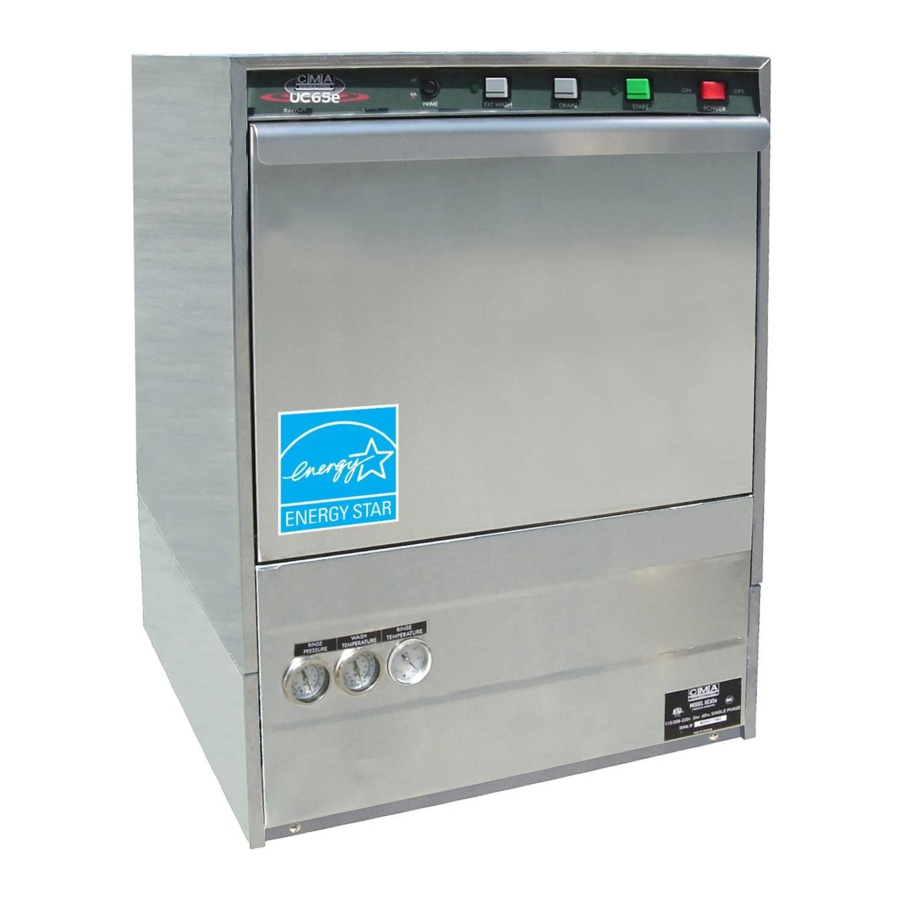
Undercounter
High Temperature
Dishwasher
Models:
UC65e
Machine Serial No.
Issue Date: 11.18.13
Manual P/N
0512865 rev. D
For machines beginning with S/N W090217876 and above
Printed in the USA
Advertisement
Chapters
Table of Contents

Related Manuals for CMA Dishmachines UC65e


Summary of Contents for CMA Dishmachines UC65e
- Page 1 CMA Dishmachines 12700 Knott Avenue Garden Grove, CA 92841 Toll Free: 1- (800) 854-6417 Fax: 1- (714) 895-2141 placement Parts Installation/Operation Manual with Service Re Undercounter High Temperature Dishwasher Models: UC65e UC65e Machine Serial No. Issue Date: 11.18.13 Manual P/N 0512865 rev.
- Page 2 For future reference, record your dishwasher information in the box below. Model Number__________________________ Serial Number_______________________ Voltage________________Hertz_____________ Phase__________________ Service Agent __________________________________ Tel:______________________ Parts Distributor _________________________________ Tel:______________________ National Service Department CMA Dishmachines 12700 Knott Avenue Garden Grove, CA 92841 Toll-free: 1 (800) 854-6417 Fax: 1 (714) 895-2141 ATTENTION: The model no., serial no., voltage, Hz...
-
Page 3: Revision History
We reserve the right to make changes to these instructions without notice and without incurring any liability by making the changes.. • Equipment owners may request a revised manual, at no charge, by calling CMA Dishmachines at 1 (800) 854-6417. Revision Revised Serial Number... - Page 4 Model Description Model Description UC65e High temperature hot water sanitizing dishwasher with built-in 40°F/22°C rise booster heater. 208-240VAC/60/1...
-
Page 5: Table Of Contents
Table of Contents Table of Contents Model UC65e Undercounter Dishwasher Revision History........................i Model Descriptions ......................ii ....................Installation Receiving ..............1 Electrical Connections ..........2 Water Connections .............4 Drain Connections ............5 ..................Initial Start-up Booster Fill Switch ............6 Assembly ..............8 Chemical Dispensing Pumps ........9 Priming ......10... - Page 6 Blank Page This Page Intentionally Left Blank...
-
Page 7: Installation
Installation Receiving NOTE: The installation of your dishwasher must be performed by qualified service personnel. Problems due to improper installation are not covered by the Warranty. Inspect the outside of the dishwasher carton for signs of damage. Remove the carton and inspect the dishwasher for damage. Check for any accessories that may have shipped with your dishwasher. -
Page 8: Electrical Connections
Installation Electrical Connections WARNING: Electrocution or serious injury may result when working on an energized circuit. Disconnect power at the main breaker or service disconnect switch before working on the circuit. Lock-out and tag the breaker to indicate that work is being performed on the circuit. - Page 9 Installation Electrical Connections 1. Refer to the connection diagram below: 2. Machines require a 3-wire plus ground supply which includes a current carrying neutral. 3. Do not use a power cord and plug nor connect to a standard or Ground Fault Interrupter, (GFI), electrical outlet.
-
Page 10: Water Connections
Installation Water Connections Note Plumbing connections must comply with national, local plumbing and sanitary codes. IMPORTANT Make sure that the flexible water supply and drain hoses are not kinked. All models have a 6 ft. flexible hot water fill hose with a 3/4" GHT connector. A 1/2"... -
Page 11: Drain Connections
Installation Drain Connections ATTENTION Do not connect the drain hose to a disposer. The dishwasher will not drain correctly. The dishwasher has a 6ft. 3/4" I.D. drain hose. The maximum drain height connection must not exceed 3 ft.[9 m]. The recommended drain height is 17" [.4 m] or less above the floor. The drain hose is secured to the rear of the machine by a clamp to maintain a goose-neck bend in the drain hose. -
Page 12: Initial Start-Up
Initial Start-Up Filling the Booster ATTENTION VERIFY THE CORRECT VOLTAGE IS SUPPLIED TO THE MACHINE THE CORRECT SUPPLY VOLTAGE IS 115/208-240VAC/60/1. (Refer to the diagram on page 3.) Note: The dishwasher contains a built-in booster heater that was drained prior to shipment and must be filled with water before operating the dishwasher. - Page 13 Initial Start-Up Filling the Booster (continued) B) Press and hold the Booster Fill Switch down to the BOOSTER FILL position until you hear the water spraying inside the dishwasher wash tank, then release the switch. C) Push the switch up to the ON position and release. The booster tank is filled.
-
Page 14: Assembly
Initial Start-up Check List Remove any protective film from dishwasher. Check the interior for foreign material. Make sure that the dishwasher is permanently located. Make sure that all utility connections are complete. Make sure that the flexible drain hose and the hot water fill hose are not kinked. Make sure that the chemical supply containers are full and that the chemical pick-up tubes are installed in the proper containers. -
Page 15: Chemical Dispensing Pumps
Initial Start-up Chemical Dispensing Pumps ATTENTION Contact a local chemical supplier for detergent and rinse-aid chemicals. The detergent should be a non-chlorinated liquid detergent. The chemical dispensing pumps are adjusted by the chemical supplier. The dishwasher is equipped with a built-in detergent dispensing pump and rinse-aid dispensing pump. - Page 16 Initial Start-up Chemical Dispensing Pumps (continued) Chemical Injection Points The illustrations below show the location of the detergent and the rinse-aid injection points. Detergent Injection Point Rinse-aid Injection Point Detergent enters the wash tank compartment through a fitting on the rear wall of the wash tank compartment. The rinse-aid enters the final rinse piping at the top-rear of the dishwasher near the vacuum breaker.
-
Page 17: Priming
Initial Start-up Chemical Dispensing Pumps Priming the Chemical Dispensing Pumps The chemical dispensing pumps must be primed before the dishwasher is operated. A 2-position PRIME switch is located on the front control panel to do this. The Detergent dispensing pump is primed when the Prime switch is pushed UP to the DET position. -
Page 18: Adjusting
Initial Start-up Chemical Dispensing Pumps Adjusting the Chemical Dispenser Pumps The amount of detergent and rinse-aid that are dispensed during the dishwasher cycle are controlled by adjustable cams on the timer assembly. Variables such as the type of chemicals used and the hardness of the water supply often require that the timer cam settings must be changed. -
Page 19: Operation
Operation Normal Wash Mode Follow the instructions below to operate the dishwasher in a Normal Wash Mode. A Safe-T-Temp feature holds the dishwasher in a wash mode if the booster heater temperature is below 180ºF/82ºC. Turn the main power on at the main circuit breaker. Install the sump filter, overflow tube and spray arms. -
Page 20: Saf-T-Temp
Operation Normal Wash Mode (continued) Opening the door when the dishwasher is in-cycle will stop the dishwasher. The cycle will resume automatically when the dishwasher door is closed fully. 12. The final rinse cycle begins at the end of the wash cycle and runs for approximately 15-seconds Check the RINSE temperature gauge during the final rinse and make sure that it indicates a minimum of 180ºF/82ºC. -
Page 21: Cleaning And Maintenance
Cleaning and Maintenance Cleaning After Each Meal Period or every 8 Hours of Operation. Press the lighted power switch to the OFF position. The power switch light will go out. Open the door and remove the overflow tube from the wash tank sump. Inspect and clean the overflow tube rubber seal Close the door. -
Page 22: Cleaning And Maintenance
Cleaning and Maintenance Cleaning At the End of the Day Perform Steps 1-8 on the previous page. Remove the upper and lower rinse and wash spray arms. The spray arms are interchangeable. Unscrew the rinse arm pin (A). Remove the rinse arm assemblies Clean the final rinse arm nozzles using a small paper clip (B). -
Page 23: Cleaning And Maintenance
Cleaning and Maintenance De-liming Minerals accumulate on the interior surfaces of the dishwasher. The deposits have a white haze and, in cases of heavy accumulation, may appear as a granular solid. The generic name for mineral deposits is lime. The removal of lime deposits is called de-liming. Your dishwasher should be de- limed regularly;... -
Page 24: Maintenance
Cleaning and Maintenance Maintenance Follow the maintenance schedules below to keep the dishwasher operating most efficiently. Daily Maintenance Check all of the wash arm and rinse arm spray jets and clean as necessary. Make sure that the water supply is on and that the drain is not clogged. Check the temperature gauges and/or displays to ensure that they are operating. -
Page 25: Troubleshooting
Troubleshooting Troubleshooting Follow the troubleshooting guide below in the event that your dishwasher does not operate as expected. Perform the basic checks below before calling an authorized service agent: Make sure that the main water supply is turned on. Make sure that the main power is turned on. Make sure that the flexible water fill and drain hoses are not kinked. - Page 26 Blank Page This Page Intentionally Left Blank...
-
Page 27: Service Replacement Parts
Service Replacement Parts Service Replacement Parts Illustrations Page Wash Pump/Motor Assembly ..........................Booster Assembly ..............................Electrical Panel and Timer Assembly ........................Control Panel Assembly ............................Upper Final Rinse Piping Assembly ........................Wash and Rinse Spray Arm Assemblies ........................ Drain Pump and Lower Hose Assemblies ......................Wash Tank Heater and Drain Assemblies ...................... -
Page 28: Wash Pump/Motor Assembly
Wash Pump/Motor Assembly... - Page 29 Wash Pump/Motor Assembly Item Part Description Qty. 2103.01 SCREW, M4, PHIL, PAN HD. 2103.02 IMPELLER HOUSING COVER 2103.03 NUT, M6 (left-hand threads) 2103.04 WASHER, LOCK, 1/4" 2103.05 WASHER, PLAIN, M6 2103.06 IMPELLER 2103.07 SEAL 2103.30 GASKET, PUMP 2103.09 BACKPLATE, PUMP 2103.08 NUT, M4 2103.10...
-
Page 30: Booster Assembly
Booster Assembly... - Page 31 Booster Assembly Item Part Description Qty. 2103.12 HEATER, BOOSTER 4kW, 208V, 40°F RISE (Does not include gasket) 2103.13 HEATER, BOOSTER 6kW, 208V, 70°F RISE (Does not include gasket) 2103.14 GASKET, BOOSTER HEATER 2103.15 THERMOSTAT, CONTROL 195°F (Prior to S/N W120631743) 2103.36 THERMOSTAT, CONTROL 110-195°F (Beginning with S/N W120631743)
-
Page 32: Electrical Panel And Timer Assembly
Electrical Panel and Timer Assembly Item 10, Timer Assembly includes: Items 12 and 13... - Page 33 Electrical Panel and Timer Assembly Item Part Description Qty. 2103.29 THERMOSTAT, WASH TANK 2103.15 THERMOSTAT, CONTROL 195°F (Prior to S/N W120631743) 2103.36 THERMOSTAT, CONTROL 110-195°F (Beginning with S/N W120631743) 2103.63 BRACKET, THERMOSTAT (Use with Item 3 only) 2103.31 SWITCH, 3-POSITION, TOGGLE 2103.34 SCREW, NIBS RH 6-32 X 3/16"...
-
Page 34: Control Panel Assembly
Control Panel Assembly... - Page 35 Control Panel Assembly Item Part Description Qty. 2103.42 PANEL, FACIA, UC65e 2103.44 LABEL, FACIA, UC65e 2103.50 SWITCH, ON-OFF 2103.51 CONTACT, MOMENTARY, N.O. 2103.52 HOUSING, SWITCH 2103.53 BUTTON, SWITCH (GREEN) 2103.54 BUTTON, SWITCH (GREY) 2103.55 LIGHT, INDICATOR LED, 125VAC (GREEN) 2103.56 CONTACT, SWITCH (EXTENDED WASH) 2103.57...
-
Page 36: Upper Final Rinse Piping Assembly
Upper Final Rinse Piping Assembly... - Page 37 Upper Final Rinse Piping Assembly Item Part Description Qty. 2103.60 HOSE, RUBBER 1/2ID X .84OD 2103.21 CLAMP, SS GEAR-MIN. 5/16-MAX.7/8 2103.62 FITT COMP 1/4OD X 1/8MPT ELL J (Prior to S/N W120631743) 2103.26 PLUG, 1/8 HEX COUNTERSUNK (Beginning with S/N W120631743) 2103.64 MANIFOLD, RINSE 2103.65 INJECTOR FITTING 2103.66...
-
Page 38: Wash And Rinse Spray Arm Assemblies
Wash and Rinse Spray Arm Assemblies... - Page 39 Wash and Rinse Spray Arm Assemblies Item Part Description Qty. 2103.75 WASHER, 17/64 id X 9/16" OD SST 2103.76 NUT, HEX 1/40-20 NYLON INSERT SST 2103.77 HUB, UPPER WASH ARM 2103.78 WASHER, PACKING 2103.79 SCREW, RETAINING 2103.80 CLAMP, HOSE GEAR 1-1/2" SST 2103.81 HOSE, UPPER WASH ARM 2103.82...
-
Page 40: Drain Pump And Lower Hose Assemblies
Drain Pump and Lower Hose Assembly From Final Rinse Manifold To upper washarm hub... - Page 41 Drain Pump and Lower Hose Assembly Item Part Description Qty. 02104.00 HOSE, FILL 1/2" X 7' C/W 3/4" FNPS 2103.16 BOLT, HEX FLANGE, 1/4-20 X 3/8" SST 2103.18 HOSE, BOOSTER FILL, 1/2" X 1' 2103.17 CLAMP, HOSE GEAR-TYPE 5/16" 2104.04 CLAMP, HOSE GEAR-TYPE, 1", SST 2104.05 HOSE, DRAIN PUMP SUCTION...
-
Page 42: Wash Tank Heater And Drain Assemblies
Wash Tank Heater and Drain Assembly... - Page 43 Wash Tank Heater and Drain Assembly Item Part Description Qty. 2104.17 GASKET, DOOR 2104.18 HEATER, WASH TANK, 2KW, 240VAC 968.00 WASHER, SPLIT LOCK 1/4" SST 2103.67 NUT, HEX 1/4-20 SST 2104.21 O-RING 2104.22 ADAPTER, THERMOSTAT 2103.28 BUSHING, THERMOSTAT 2103.29 THERMOSTAT, WASH TANK 2104.25 ADAPTER, THERMOMETER 2103.25...
-
Page 44: Fill Solenoid Valve Assembly
Fill Solenoid Valve Assembly... - Page 45 VALVE, SOLENOID, DEMA 1/2" 115VAC/60/1 (Includes Items 1a) 03604.30 KIT, REPAIR SOLENOID VALVE, DEMA 1/2" 03604.50 FITTING, FLOW DISC, DEMA 03604.10 WASHER, FLOW, DEMA 2103.73 FITTING, BARB HOSE 2104.45 BRACKET, VALVE, UC65E 2103.16 BOLT, HEX FLANGE 1/4-20 X 3/8" SST...
-
Page 46: Detergent Pump Assembly
Detergent Pump Assembly... - Page 47 Detergent Pump Assembly Item Part Description Qty. 2104.47 STRAINER 2104.48 TUBE,1/2IDX11-7/8LG. STIFFENER 2104.49 LABEL, DETERGENT 2104.37 HOSE, 1/4ID X 3/8OD PVC 2104.51 TIE, NYLON 4" 2104.52 ELBOW, 1/4 HOSE BARB 00435.10 TUBE, SQUEEZE PUMP 00911.00 SCREW 00418.00 COVER, PUMP 00419.00 ASSEMBLY, ROLLER 00423.00 ROLLER...
-
Page 48: Rinse-Aid Pump Assembly
Rinse-Aid Pump Assembly... - Page 49 Rinse-Aid Pump Assembly Item Part Description Qty. 2104.47 STRAINER 2104.48 TUBE,1/2ID X 11-7/8LG. STIFFENER 2104.49 LABEL, RINSE AID 2104.50 TUBING, 1/8" OD X 1/16 ID" 2104.51 TIE, CABLE 4" 00836.00 TUBE, SQUEEZE PUMP 00911.00 SCREW 00418.00 COVER, PUMP 00419.00 ASSEMBLY, ROLLER 00423.00 ROLLER 00422.00...
-
Page 50: Panel Assembly
Panel Assembly... - Page 51 LABEL, GUAGE 2104.63 GAUGE, PRESSURE 0-60PSI 2103.25 THERMOMETER, 2" DIAL, 7' CAPILLARY 2104.65 SCREW, 1/4-20 X 5/8" TRUSS HD. PHIL. SST 2104.66 PANEL, FRONT UC65e 2104.67 FOOT, ADJUSTING 2104.68 NUT, KEPS, 10-32 SST 2104.69 WRAP, OUTER PANEL 2104.70 CLAMP, DOUBLE CONDUIT 2103.39...
-
Page 52: Door Assembly
Door Assembly... - Page 53 Door Assembly Item Part Description Qty. 2104.73 DOOR WELDED ASSY 2104.76 ARM, DOOR SPRING 2104.77 SPRING, DOOR 2104.78 ACTUATOR, DOOR SWITCH 2103.41 SCREW, 8-32 X 3/16" PHIL. SST 2104.88 SEAL, DOOR DRIP, RH 2104.87 SEAL, DOOR DRIP, LH...
- Page 54 Dish Racks, Line Strainer, PRV...
- Page 55 Dish Racks, Line Strainer, PRV Item Part Description Qty. 2104.80 DISH RACK, FLAT-BOTTOM 2104.81 DISH RACK, PEG 2104.82 STRAINER, LINE 1/2" BRONZE (OPTIONAL) 2104.83 VALVE, PRESSURE REGULATING (PRV)
-
Page 56: Dish Racks, Line Strainer And Pressure Regulating Vavle (Prv)
Electrical Schematic,Timer Chart, Fill/Drain Timer Electrical Schematic,Timer Chart Illustrations Page Model UC65e Electrical Schematic ..................Timer Chart ........................... -
Page 57: Electrical Schematic
Model UC65e - Electrical Schematic TO CUSTOMERS DISCONNECT SWITCH PER LOCAL ELECTRICAL CODE 115-208/230V/1PH 60HZ WHTR DRAIN SWITCH DOOR SWITCH EXT. WASH SWITCH 1HTR BOOSTER HEAT 208/230 VAC 4 kW START SWITCH SR1-2 DIAGRAM STATE END OF CYCLE POWER-OFF DOOR-OPENED... -
Page 58: Timer Chart
Timer Chart - Model UC65e... -
Page 59: Service Parts Installation Instructions
Service Parts Installation Instructions Service Parts Installation Instructions Booster Thermostat P/N 2103.36 ................54 Pressure Gauge Piping Change .................56 Fill/Drain Timer Conversion P/N 2103.43 ..............58 Fill/Drain Timer - Theory of Operation ................62... -
Page 60: Booster Thermostat P/N 109069
Service Parts Installation - Booster Thermostat P/N 2103.36 Beginning with S/N W120631743, the booster control thermostat, P/N 2103.36 replaced the existing thermostat, 2103.15. For machines built prior to S/N W120631743, the old thermostat P/N 203.15 must be used unless a new booster tank, P/N 2103.20, is installed at the same time. Refer to the photographs below and on the next page for installation instructions. - Page 61 Service Parts Installation - Booster Thermostat P/N 2103.36...
-
Page 62: Pressure Gauge Piping Change
Service Parts Installation - Pressure Gauge Piping Change Beginning with S/N W120631743, the pressure gauge tubing has been relocated from the top right rear corner of the machine to the booster located on the base of the machine. This change improves the operation of the final rinse pressure gauge. Refer to the illustrations below and on the next page for installation instructions. - Page 63 Service Parts Installation - Pressure Gauge Pipiing Change From Fill Valve Parts list on pages 24-25. New parts needed for the conversion. Relocated from rear of the machine.
-
Page 64: Fill/Drain Timer P/N 0713133
Service Parts Installation - Fill/Drain TImer Conversion - P/N 2103.43 Fill/Drain Timer Conversion - P/N 2103.43 All S/N's have a new fill/drain timer, P/N 2103.43. This new timer is slightly larger than previous timers but it still mounts in the same location as previous timers. The only function of the fill/drain timer is to fill the machine at the beginning of the day and to drain the machine at the end of the day. - Page 65 Service Parts Installation - Fill/Drain Timer Conversion - P/N 2103.43 If your machine has the Cam Timer with black cams, then the board mounting screws can be accessed without removing the timer drive motor. If your machine has white and gray timer cams (A), then it may be necessary to remove the timer drive motor to access one of the fill/drain timer mounting screws (B).
- Page 66 Service Parts Installation - Fill/Drain TImer Conversion - P/N 2103.43 Fill/Drain Timer Conversion - P/N 2103.43 continued from previous page...
- Page 67 Service Parts Installation - Fill/Drain Timer Conversion - P/N 2103.43 Fill/Drain Timer Conversion - P/N 2103.43 Connect the wires as shown on the previous page and reinstall the mounting screws. Reinstall the timer motor. The new board shown with wires connected and mounting screws installed. The installation is complete.
-
Page 68: Fill/Drain Timer -Theory Of Operation
Fill/Drain Timer -Theory of Operation Fill/Drain Timer Board - Theory of Operation LED's 1, 2, and 3 are illuminated during a normal wash/rinse cycle. The new fill/drain timer board has built-in diagnostics. LED's (1, 2, 3, and 4) illuminate under the following conditions: a) LED 1 illuminates when power from circuit breaker is ON and booster/fill switch (service switch) is ON.
Need help?
Do you have a question about the UC65e and is the answer not in the manual?
Questions and answers