Table of Contents
Advertisement
Quick Links
Installation/Operation Manual with Service Replacement Parts
CMA Dishmachines
12700 Knott Avenue
Garden Grove, CA 92841
Toll Free: 1 (800) 854-6417
Fax:
1 (714) 895-2141
CMA Dishmachines
12700 Knott Avenue
Garden Grove, CA 92841
Toll Free:
1- (800) 854-6417
Fax:
1- (714) 895-2141
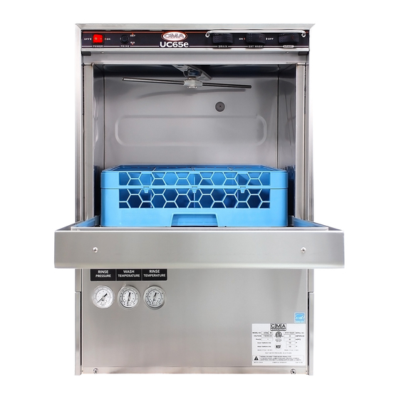
Undercounter
High Temperature
Dishwasher
Model:
UC65e M2
Machine Serial No.
Issue Date: 4.6.17
Manual P/N
10310.00 rev. A
For machines beginning with S/N W160861096 and above
Printed in the USA
Advertisement
Chapters
Table of Contents

Subscribe to Our Youtube Channel
Related Manuals for CMA Dishmachines UC65e M2


Summary of Contents for CMA Dishmachines UC65e M2
- Page 1 Fax: 1- (714) 895-2141 Installation/Operation Manual with Service Replacement Parts Undercounter High Temperature Dishwasher Model: UC65e M2 Machine Serial No. Issue Date: 4.6.17 Manual P/N 10310.00 rev. A For machines beginning with S/N W160861096 and above CMA Dishmachines Printed in the USA...
- Page 2 For future reference, record your dishwasher information in the box below. Model Number__________________________ Serial Number_______________________ Voltage________________Hertz_____________ Phase__________________ Service Agent __________________________________ Tel:______________________ Parts Distributor _________________________________ Tel:______________________ National Service Department CMA Dishmachines 12700 Knott Avenue Garden Grove, CA 92841 Toll-free: 1 (800) 854-6417 Fax: 1 (714) 895-2141 ATTENTION: The model no., serial no., voltage, Hz...
-
Page 3: Revision History
We reserve the right to make changes to these instructions without notice and without incurring any liability by making the changes.. • Equipment owners may request a revised manual, at no charge, by calling CMA Dishmachines at 1 (800) 854-6417. Revision Revised Serial Number... - Page 4 Model Description Model Description UC65e M2 High temperature hot water sanitizing dishwasher with built-in 40°F/22°C rise booster heater. 208-240VAC/60/1...
-
Page 5: Table Of Contents
Table of Contents Table of Contents Model UC65e M2 Undercounter Dishwasher Revision History........................i Model Descriptions ......................ii Installation ..........................Receiving ............1 Electrical Connections .........2 Water Connections ..........4 Drain Connections ..........4 Initial Start-up ......................... Check List ............6 Chemical Dispensing Pumps ......7 Priming ..............9 Adjusting .............10... - Page 6 Blank Page This Page Intentionally Left Blank...
-
Page 7: Installation
Installation Receiving NOTE: The installation of your dishwasher must be performed by qualified service personnel. Problems due to improper installation are not covered by the Warranty. Inspect the outside of the dishwasher carton for signs of damage. Remove the carton and inspect the dishwasher for damage. Check for any accessories that may have shipped with your dishwasher. -
Page 8: Electrical Connections
Installation Electrical Connections WARNING: Electrocution may occur when working on ener- gized circuits. Disconnect power at the main breaker or service disconnect switch, then lock out and tag it to indicate that work is being performed on the circuit. CAUTION: Permanent damage to the dishwasher may occur if it is improperly connected to the main electrical supply. - Page 9 Installation Electrical Connections NOTE: A qualified electrician must connect the main incoming power to the dishwasher in accordance with all local codes and regulations or in the absence of local codes in accordance with the National Electrical Code. FOLLOW THE STEPS BELOW TO CONNECT THE INCOMING POWER. REMOVE THE LEFT SCREW ON THE FRONT LIP OF THE TERMINAL BOX.
-
Page 10: Water Connections
Installation Water Connections NOTE: Plumbing connections must comply with national or local plumbing and sanitary codes. Make sure that the flexible water supply and drain hoses are not kinked. All models have a 6 ft. flexible hot water fill hose with a 3/4" GHT connector. A 1/2"... - Page 11 Installation Drain Connections DRAIN MUST BE VENTED TO PREVENT SYPHONING DRAIN HOSE 3/4" MNPT HOSE ADAPTER *18" 1-1/2" WYE OPTIMU M FITTING FT. MAX The dishwasher flexible drain hose must be connected to a WYE FITTING. DO NOT REPOSITION THE DRAIN HOSE DO NOT ADD AN EXTENSION TO THE DRAIN HOSE...
-
Page 12: Initial Start-Up
Initial Start-up Check List Remove any protective film from dishwasher. Check the interior for foreign material. Make sure that the dishwasher is permanently located. Make sure that all utility connections are complete. Make sure that the flexible drain hose and the hot water fill hose are not kinked. Make sure that the chemical supply containers are full and that the chemical pick-up tubes are installed in the proper containers. -
Page 13: Chemical Dispensing Pumps
Initial Start-up Chemical Dispensing Pumps ! ATTENTION ! Contact a local chemical supplier for detergent and rinse-aid chemicals. The detergent should be a non-chlorinated liquid detergent. The chemical dispensing pumps are adjusted by the chemical supplier. The dishwasher is equipped with a built-in detergent dispensing pump and rinse-aid dispensing pump. - Page 14 Initial Start-up Chemical Dispensing Pumps (continued) Your chemical supplier should adjust the dispensers for the supplied product. 10. Place the chemical supply containers as close to the dishwasher as possible. 11. Do not elevate the chemical containers above the finished floor. Chemical Injection Points The illustrations below show the location of the detergent and the rinse-aid injection points.
-
Page 15: Priming
Initial Start-up Chemical Dispensing Pumps Priming the Chemical Dispensing Pumps The chemical dispensing pumps must be primed during initial start-up and whenever a chemical container . A momemtary two position PRIME switch is located on the front control panel to do this. -
Page 16: Adjusting
Initial Start-up Chemical Dispensing Pumps Adjusting the Chemical Dispenser Pumps The amount of detergent and rinse-aid that are dispensed during the dishwasher cycle are controlled by adjustable cams on the timer assembly. Variables such as the type of chemicals used and the hardness of the water supply often require that the timer cam settings must be changed. -
Page 17: Operation
Operation Normal Wash Mode Follow the instructions below to operate the dishwasher in a Normal Wash Mode. A Safe-T-Temp feature holds the dishwasher in a wash mode if the booster heater temperature is below 180ºF/82ºC. Turn the main power on at the main circuit breaker. Install the sump filter, overflow tube and spray arms. -
Page 18: Saf-T-Temp
Operation Normal Wash Mode (continued) 12. Opening the door when the dishwasher is in-cycle will stop the dishwasher. The cycle will resume automatically when the dishwasher door is closed fully. 13. The final rinse cycle begins at the end of the wash cycle and runs for approximately 15 seconds Check the RINSE temperature gauge during the final rinse and make sure that it indicates a minimum of 180ºF/82ºC. -
Page 19: Cleaning And Maintenance
Cleaning and Maintenance Cleaning After Each Meal Period or every 8 Hours of Operation. Press the lighted power switch to the OFF position. The power switch light will go out. Open the door and remove the overflow tube from the wash tank sump. Inspect and clean the overflow tube rubber seal Close the door. - Page 20 Cleaning and Maintenance Cleaning At the End of the Day Perform Steps 1-8 on the previous page. Remove the upper and lower rinse and wash spray arms. The spray arms are interchangeable. Unscrew the rinse arm pin (A). Remove the rinse arm assemblies Clean the final rinse arm nozzles using a small paper clip (B).
-
Page 21: Deliming
Cleaning and Maintenance Deliming Minerals accumulate on the interior surfaces of the dishwasher. The deposits have a white haze and, in cases of heavy accumulation, may appear as a granular solid. The generic name for mineral deposits is lime. The removal of lime deposits is called Deliming. Your dishwasher should be de- limed regularly;... -
Page 22: Maintenance
Cleaning and Maintenance Maintenance Follow the maintenance schedules below to keep the dishwasher operating most efficiently. Daily Maintenance Check all of the wash arm and rinse arm spray jets and clean as necessary. Make sure that the water supply is on and that the drain is not clogged. Check the temperature gauges and/or displays to ensure that they are operating. -
Page 23: Troubleshooting
Troubleshooting Troubleshooting Follow the troubleshooting guide below in the event that your dishwasher does not operate as expected. Perform the basic checks below before calling an authorized service agent: Make sure that the main water supply is turned on. Make sure that the main power is turned on. Make sure that the flexible water fill and drain hoses are not kinked. - Page 24 Blank Page This Page Intentionally Left Blank...
-
Page 25: Service Replacement Parts
Service Replacement Parts Service Replacement Parts Illustrations Page Wash Pump/Motor ..............................Booster ................................... Power Box Wiring ..............................Electrical Panel and Timer ............................Control Panel ................................Upper Final Rinse Piping ............................Wash and Rinse Spray Arms ..........................Drain Pump and Hoses ............................Wash Tank Heater and Drain.......................... -
Page 26: Wash Pump/Motor
Wash Pump/Motor... - Page 27 Wash Pump/Motor Item Part Description Qty. 02103.01 SCREW, M4, PHIL, PAN HEAD. 02103.02 IMPELLER HOUSING COVER 02103.03 NUT, M6 (left-hand threads) 02103.04 WASHER, LOCK, 1/4" 02103.05 WASHER, PLAIN, M6 02103.06 IMPELLER 02103.07 SEAL 02103.30 GASKET, PUMP 02103.09 BACKPLATE, PUMP 02103.08 NUT, M4 02103.10 PUMP/MOTOR ASSEMBLY COMPLETE, 220VAC/60/1...
-
Page 28: Booster
Booster... - Page 29 Booster Item Part Description Qty. 02103.12 HEATER, BOOSTER 4kW, 208V, 40°F RISE (Does not include gasket) 02103.13* HEATER, BOOSTER 6kW, 208V, 70°F RISE (Does not include gasket) 02103.14 GASKET, BOOSTER HEATER 02103.15 THERMOSTAT, CONTROL 195°F 02103.16 BOLT, HEX FLANGE, 1/4-20 X 3/8" 40012.10 ELBOW, 3/8"...
-
Page 30: Power Box Wiring
Power Wiring Box... - Page 31 Power Wiring Box Item Part Description Qty. 02106.02 LABEL, CONNECTION BOX 02106.03 COVER, BOX WIRING 02106.04 BOX, WIRING 00421.51 SCREW, 6-32 X 1/4" 13426.50 LUG, GROUND 00905.82 SCREW, 1/4-20 X 3/8" 02106.05 BLOCK, TERMINAL, 4-POLE 00940.50 SCREW, 10-32 X 3/8", TRUSS HEAD. 02106.15 BUSHING, STRAIN RELIEF, SMALL 02103.48...
-
Page 32: Electrical Panel And Timer
Electrical Panel and Timer... - Page 33 Electrical Panel and Timer Item Part Description Qty. 02103.93 SCREW, TRUSS HEAD, 8-32 X 1/4" 00411.00 SWITCH, TIMER 00501.00 MOTOR, TIMER 00408.60 ASSEMBLY, TIMER (Includes Items 2, 3) 00907.00 SCREW, 6-32 X 1/2" 02103.40 RELAY, 15 AMP, 120VAC COIL 00631.00 RELAY, 120VAC, 2PDT 43030.00 THERMOSTAT, WASH...
-
Page 34: Control Panel
Control Panel... - Page 35 Item Part Description Qty. 03485.00 GUARD, SWITCH (Includes items 11 & 12) 02103.58 GASKET, STEAM 02106.09 LABEL, FACIA, UC65e M2 15523.10 SWITCH, ROCKER, START MOMENTARY 15524.00 SWITCH, ROCKER, MAINTAINED 15523.50 SWITCH, ROCKER, DRAIN/FILL 00911.10 SCREW, TRUSS SLOT, 8-32 X 3/8"...
-
Page 36: Upper Final Rinse Piping
Upper Final Rinse Piping... - Page 37 Upper Final Rinse Piping Item Part Description Qty. 03107.50 HOSE, RUBBER 1/2ID X .84OD 03101.47 CLAMP, GEAR 02103.62 FITT COMP 1/4OD X 1/8MPT ELL J 03232.00 PLUG, 1/8 HEX COUNTERSUNK 02103.64 MANIFOLD, RINSE 02103.65 INJECTOR FITTING 00425.54 TUBING, 1/4" NATURAL 00923.50 NUT, KEP 1/4-20 02103.04...
-
Page 38: Wash And Rinse Spray Arms
Wash and Rinse Spray Arms... - Page 39 Wash and Rinse Spray Arms Item Part Description Qty. 00426.00 WASHER, 5/16" SS WASHER 00912.00 NUT, 1/40-20 NYLON LOCK NUT 02103.77 HUB, UPPER WASH ARM 02103.78 WASHER, PACKING 02103.79 SCREW, RETAINING 50109.00 CLAMP, HOSE #28 02103.81 HOSE, UPPER WASH ARM 02103.82 BEARING ASSEMBLY 02103.83...
-
Page 40: Drain Pump And Hoses
Drain Pump and Hoses From Final Rinse Manifold To upper washarm hub TO BOOSTER INLET... - Page 41 Drain Pump and Hoses Item Part Description Qty. 02104.00 HOSE, FILL 1/2" X 7' C/W 3/4" FNPS 02103.16 BOLT, HEX FLANGE, 1/4-20 X 3/8" 02103.18 HOSE, BOOSTER FILL, 1/2" X 1' 03101.47 CLAMP, HOSE GEAR-TYPE 5/16" 03101.00 CLAMP, HOSE GEAR-TYPE, 1" 02104.05 HOSE, DRAIN PUMP SUCTION 02104.06...
-
Page 42: Wash Tank Heater And Drain
Wash Tank Heater and Drain... - Page 43 Wash Tank Heater and Drain Item Part Description Qty. 02104.17 GASKET, DOOR 02104.18 HEATER, WASH TANK, 2KW, 240VAC 00968.00 WASHER, SPLIT LOCK 1/4" 00923.50 NUT, HEX 1/4-20 02104.21 O-RING 02104.22 ADAPTER, THERMOSTAT 02103.28 BUSHING, THERMOSTAT 43030.00 THERMOSTAT, WASH TANK 02104.25 ADAPTER, THERMOMETER 02103.25 THERMOMETER, 2"...
-
Page 44: Fill Solenoid Valve
Fill Solenoid Valve... - Page 45 Fill Solenoid Valve Item Part Description Qty. 03603.10 WATER SOLENOID 1/2" J/E COMPLETE (Includes Items 2-6) 00738.10 WATER SOLENOID COIL J/E 03603.20 1/2" WATER SOLENOID BONNET 00786.00 WATER SOLENOID VALVE PLUNGER 00707.00 1/2" WATER SOLENOID REPAIR KIT 40013.00 FITTING, BARB HOSE 02106.11 BRACKET, VALVE, UC65E 02103.16...
-
Page 46: Detergent Pump
Detergent Pump... - Page 47 Detergent Pump Item Part Description Qty. 02104.47 STRAINER 02104.48 TUBE,STIFFENER, 1/2" ID X 11-7/8" LG. 43078.05 LABEL, DETERGENT 02104.37 HOSE, 1/4ID X 3/8OD PVC 02104.51 TIE, NYLON 4" 02257.00 TUBE, SQUEEZE 8" 00911.00 SCREW, 8-32 X 1/2" PANHEAD 00418.00 COVER, PUMP 00419.00 ASSEMBLY, ROLLER 00919.00...
-
Page 48: Rinse-Aid Pump
Rinse-Aid Pump... - Page 49 Rinse-Aid Pump Item Part Description Qty. 02104.47 STRAINER 02104.48 TUBE,STIFFENER, 1/2" ID X 11-7/8" LG. 40378.08 LABEL, RINSE AID 07237.00 TUBING, 1/8" ID X 1/4" OD 00931.00 TIE, CABLE 4-1/2" 02257.00 TUBE, SQUEEZE 8" 00911.00 SCREW, 8-32 X 1/2" PANHEAD 00418.00 COVER, PUMP 00419.00...
-
Page 50: Panels
Panels... - Page 51 Panels Item Part Description Qty. 02103.62 FITTING, COMP 1/4" OD X 1/8 MPT ELL J 02104.60 ADAPTOR, 1/8" NPT X 1/4" TUBE 00425.54 TUBING, CHEMICAL 1/4" NATURAL 02104.62 LABEL, GAUGE 02104.63 GAUGE, PRESSURE 0-60PSI 02103.25 THERMOMETER, 2" DIAL, 7' CAPILLARY 00929.00 BOLT, 1/4-20 X 3/4"...
-
Page 52: Door
Door... - Page 53 Door Item Part Description Qty. 02104.73 DOOR WELDED ASSY 02104.76 ARM, DOOR SPRING 02104.77 SPRING, DOOR 02104.78 ACTUATOR, DOOR SWITCH 00911.10 SCREW, 8-32 X 3/8" TRUSS HEAD 02104.88 SEAL, DOOR HINGE, RH 02104.87 SEAL, DOOR HINGE, LH...
-
Page 54: Dish Racks, Line Strainer And Prv
Dish Racks, Line Strainer, PRV... - Page 55 Dish Racks, Line Strainer, PRV Item Part Description Qty. 12960.01 DISH RACK, BOWL 12960.03 DISH RACK, PEG 03602.50 STRAINER, LINE 1/2" Y 13602.20 VALVE, PRESSURE REGULATING (PRV)
-
Page 56: Electrical Schematic
Electrical Schematic... -
Page 57: Timing Chart
Timing Chart... - Page 58 Blank Page This Page Intentionally Left Blank...
Need help?
Do you have a question about the UC65e M2 and is the answer not in the manual?
Questions and answers