
Subscribe to Our Youtube Channel
Related Manuals for CMA Dishmachines CMA-44 L.T.


Summary of Contents for CMA Dishmachines CMA-44 L.T.
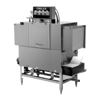
- Page 1 MODEL MODEL CMA-44 CMA-44 INSTALLATION & INSTALLATION & OPERATION OPERATION MANUAL MANUAL REV 2.16B CMA DISHMACHINES 12700 KNOTT AVENUE GARDEN GROVE CALIFORNIA 92841 800-854-6417 FAX 714-895-2141...
-
Page 2: Table Of Contents
Chemical Dispensers ....................12 2.3.8.2. Hood Fan Motor ......................12 2.3.9. CMA-44 Heater ........................12 2.4. Safety Tips for the CMA-44 ......................13 OPERATION ......................14 3.1. Initial Setup ..........................14 3.1.1. Auto Fill Timer/ Auto Re- Fill Timer ..................14 3.1.2. -
Page 3: Specifications
STANDARD TABLE HEIGHT 32 ½” adjusts to 34” MAX CLEARANCE FOR DISHES 19” STRANDARD RACKS 19 ¾” x 19 ¾” VOLTS PHASE AMPS ELECTRICAL RATING 10 kW HEATER SHIPPING WEIGHT 600# APPROXIMATE Page MODEL CMA-44 Installation & Operation Manual Rev. 2 .15B... -
Page 4: Getting Started
The CMA-44 features a scrap tray that may be emptied on a periodic basis without interruption of the flow of work and the manner in which the tank is filled ensures that the dishes are always rinsed with fresh water instead of re-circulated water. -
Page 5: Receiving And Installation
All of the spray arms should be inserted and in place over the wash tank compartments. There are a total of four curtains used in the CMA-44; two are long- narrow, two are short- wide. The two long-narrow curtains have shorter rods than the other two curtains. The short rods hold the curtains at the entrance and exit of the machine. -
Page 6: Receiving And Installation (Old Models)
All of the spray arms should be inserted and in place over the wash tank compartments. There are a total of seven curtains used in the CMA-44; two are long-narrow, four are long-wide and one is short. The two long-narrow curtains and the one short curtain have shorter rods than the other four (long-wide) curtains. -
Page 7: Electrical
CMA-44 dishwasher (see specification sheet page 2). Connect the wire that has the highest voltage (stinger lead) to the main contactor’s power terminal L2. Power lead wires (L1, L2 and L3) used for the CMA-44 at installation must comply with all local and State electrical codes. - Page 8 5. The machine must be running to set the pressure regulator. While the machine is in the FINAL RINSE CYCLE, adjust the pressure regulator to 20 PSI. See section for detailed instructions. 3.1.3 Rinse Pressure Regulator Page MODEL CMA-44 Installation & Operation Manual Rev. 2 .15B...
-
Page 9: Scrap Tray Assembly And Overflow Chute Installation
¼” SS Flat Washers, and ¼-20 Nylon Lock Nuts provided. 4. Set the scrap trap body—with the scrap trap drawer inserted—into position on the scrap trap holder. 5. Attach the drain as specified in section 2.3.2 Plumbing Page MODEL CMA-44 Installation & Operation Manual Rev. 2 .15B... -
Page 10: Pump Impeller Note
Figure 2.2.5 and damaging the motor. Removal: The Nylon Lock Nut indicated by the arrow in must be removed before Figure 2.2.5 attempting to remove the water pump impeller. Page MODEL CMA-44 Installation & Operation Manual Rev. 2 .15B... -
Page 11: Optional Hood Adapter (Set Of Two)
2.3.6. Optional Hood Adapter (Set of Two) An optional Hood Adapter set (P/N 13901.82) is available. The dimensions for proper installation are given below. Vents 53-½" Measure 4” x 16” 9-½" 65" Leg Adj 66” Page MODEL CMA-44 Installation & Operation Manual Rev. 2 .15B... -
Page 12: Optional Freestanding Scrap Trap And Adaptor Kit
Scrap Trap Flange Nut 00914.00 1/4-20 x 3/4" Hex Head Bolt 01308.00 Scrap Trap Flange Gasket 13512.00 Scrap Trap Adaptor 13512.10 Scrap Trap Adaptor Flange 01560.00 Scrap Trap, Freestanding Not Supplied Page MODEL CMA-44 Installation & Operation Manual Rev. 2 .15B... -
Page 13: Field Installed Accessories
The heater switch should always be turned off when the machine is not in operation. NOTE: Electrical and plumbing connections must be made by a qualified person who will comply with all available Federal, State, and Local Health, Electrical, Plumbing and Safety codes Page MODEL CMA-44 Installation & Operation Manual Rev. 2 .15B... -
Page 14: Safety Tips For The Cma-44
When cleaning, do not spray water directly on the motors. : When removing the final rinse arms for cleaning, exercise caution. The final CAUTION rinse arms may be filled with chemicals and/or under pressure. Page MODEL CMA-44 Installation & Operation Manual Rev. 2 .15B... -
Page 15: Operation
Initial Setup 3.1.1. Auto Fill Timer/ Auto Re- Fill Timer Both timers for the CMA-44 are set at the factory, but may need to be adjusted at the time of installation depending on supply water pressure. When the power switch is activated, the machine should fill until water begins to overflow into the scrap tray, at which point it should be set to stop filling. -
Page 16: Rinse Pressure Regulator
3.1.4. Wash Tank Temperature The wash tank temperature for the CMA-44 is set at the factory. Should you ever find a need to adjust it—after replacement of the thermostat for example—simply perform steps 1 through 4 in section 3.2 Beginning Operation. -
Page 17: Beginning Operation
4. Be sure to place the dishes correctly. If they become dislodged, they could interfere with the trip switch lever and interrupt the operation of the machine. RACK TRAVEL Page MODEL CMA-44 Installation & Operation Manual Rev. 2 .15B... -
Page 18: Chemical Dispensing
Low Temp applications. The sanitizing pump operates when the fresh water enters the machine during final rinse. The water is treated at 50 PPM (parts per million). The Page MODEL CMA-44 Installation & Operation Manual Rev. 2 .15B... -
Page 19: Regular Service And Maintenance Checklist
Check that the float switch is working properly (this will also cause the heater contactor to pull in and drop out when actuated). 6. Replace all the strainer trays into their proper position and fill the machine. Page MODEL CMA-44 Installation & Operation Manual Rev. 2 .15B... - Page 20 15. Using an all-purpose cleaner or stainless steel polish, clean up the outside of the machine to keep it looking nice. 16. Once this is done, fill out a service report and take it to the manager. Page MODEL CMA-44 Installation & Operation Manual Rev. 2 .15B...
-
Page 21: Quick Service Guide
Clogged spray jets Check and clean Motor rotation, wrong direction See wiring instruction on motor for proper rotation Debris stuck in pump cover/damaged impeller Check and clean/replace impeller, P/N 03222.85 Page MODEL CMA-44 Installation & Operation Manual Rev. 2 .15B... -
Page 22: Trouble Shooting
Drain valves open Close completely Low spray arm pressure Tank water level low Check rinse pressure, drain valve open Clogged jets Clean jets Connect motors to reverse impeller Motors connected wrong direction Page MODEL CMA-44 Installation & Operation Manual Rev. 2 .15B... -
Page 23: Cma-44 Customer Notice
Customer Notice 4. CMA-44 Customer Notice Page MODEL CMA-44 Installation & Operation Manual Rev. 2 .15B... - Page 24 Lines to chemical buckets found in wrong containers or empty. (Lines to the buckets are color-coded.) Lessee’s service responsibility shall be limited to its initial orientation, delivery of chemicals, adjustment of chemical injection system, and replacement of parts found to be worn or defective. Page MODEL CMA-44 Installation & Operation Manual Rev. 2 .15B...
-
Page 25: Electrical Diagram
Electrical Diagrams 5. Electrical Diagram Page MODEL CMA-44 Installation & Operation Manual Rev. 2 .15B... -
Page 26: Electrical Diagram (Old Models)
Electrical Diagrams 6. Electrical Diagram (Old Models) Page MODEL CMA-44 Installation & Operation Manual Rev. 2 .15B... -
Page 27: Electrical Diagram Cma-44 480/575/600 V
Electrical Diagrams 7. Electrical Diagram CMA-44 480/575/600 V Page MODEL CMA-44 Installation & Operation Manual Rev. 2 .15B...
Need help?
Do you have a question about the CMA-44 L.T. and is the answer not in the manual?
Questions and answers