Garmin G3X Pilot's Manual
Hide thumbs
Also See for G3X:
- User manual ,
- Installation manual (1011 pages) ,
- Pilot's manual (426 pages)
Table of Contents
Advertisement
Quick Links
Advertisement
Table of Contents

Related Manuals for Garmin G3X


Summary of Contents for Garmin G3X
- Page 1 ™ Pilot’s Guide...
- Page 3 SYSTEM OVERVIEW FLIGHT INSTRUMENTS CNS INTERFACE GPS NAVIGATION FLIGHT PLANNING HAZARD AVOIDANCE ADDITIONAL FEATURES AFCS ANNUNCIATIONS & ALERTS APPENDIX INDEX...
- Page 5 Garmin Ltd. or its ® ® ® ® subsidiaries. G3X is a trademark of Garmin Ltd. or its subsidiaries. These trademarks may not be ™ used without the express permission of Garmin. Jeppesen is a registered trademark of Jeppesen, Inc. ®...
- Page 6 Warnings, Cautions & Notes WARNING: Navigation and terrain separation must NOT be predicated upon the use of the terrain function. The G3X Terrain Proximity feature is NOT intended to be used as a primary reference for terrain avoidance and does not relieve the pilot from the responsibility of being aware of surroundings during flight.
- Page 7 System and is solely responsible for its accuracy and maintenance. The GPS system is subject to changes which could affect the accuracy and performance of all GPS equipment. Portions of the Garmin G3X utilize GPS as a precision electronic NAVigation AID (NAVAID). Therefore, as with all NAVAIDs, informa- tion presented by the G3X can be misused or misinterpreted and, therefore, become unsafe.
- Page 8 WARNING: Do not use the approach information provided by the VFR navigation database residing within the G3X as a means of navigating any instrument approach. The G3X VFR navigation database is limited to pres- ent only the waypoints for the final approach leg of a published procedure.
- Page 9 Although unlikely, it may be possible for erroneous operation to occur without a fault indication shown by the G3X. It is thus the responsibility of the pilot to detect such an occurrence by means of cross-checking with all redundant or correlated information available in the cockpit.
- Page 10 Warnings, Cautions & Notes Blank Page Garmin G3X Pilot’s Guide 190-01115-00 Rev. K...
- Page 11 Added ability to use VNAV when using an external GPS navigation Source • Added Softkey to Terrain Page to quickly enabled/disable terrain alerts • Added display of Navaid frequency to PFD bearing pointer data fields RR-1 190-01115-00 Rev. K Garmin G3X Pilot’s Guide...
- Page 12 System Software Version 6.00 to 6.10: • Added baro minimums altitude reference bug and audio alert to PFD 2011 • Changed CRS Softkey on PFD Page to indicate which course it controls (LOC, VOR, or OBS). RR-2 Garmin G3X Pilot’s Guide 190-01115-00 Rev. K...
- Page 13 Lean Mode is active • Changed AP NAV Softkey on PFD Page to cancel armed GS Mode on the first press if GPS Mode is active and LOC and GS Modes are both armed RR-3 190-01115-00 Rev. K Garmin G3X Pilot’s Guide...
- Page 14 Added support for GTS 8xx active traffic system. • Added support for GNS 480. System Software Version 6.40 to 7.00: July, 2012 • Added GDL39 Support August, System Software Version 7.00 to 7.20: • Added TargetTrend 2012 ™ RR-4 Garmin G3X Pilot’s Guide 190-01115-00 Rev. K...
- Page 15 Added GMC 305 AFCS Controller support • Added GSU 25 AHRS support • Added GAP 26 Pitot-AOA Mast support • Added GSA 28 Auto Pilot Servo support • Added GEA 24 Engine/Airframe support RR-5 190-01115-00 Rev. K Garmin G3X Pilot’s Guide...
- Page 16 Blank Page RR-6 Garmin G3X Pilot’s Guide 190-01115-00 Rev. K...
-
Page 17: Table Of Contents
Table of Contents Section 1 System Overview ....................1 1.1 Line Replaceable Units ..................... 1 G3X Single Display (Examples) ....................7 G3X Dual Display (Examples) ....................9 Split-Screen vs. Full-Screen Configurations ................12 External Navigators (Optional) .................... 13 Automatic Flight Control System (Optional) ................. 14 1.2 Display Overview ...................... - Page 18 Map Range ........................137 Map Panning ........................138 Fuel Range Ring ....................... 140 Measuring Bearing and Distance ..................141 Topography ........................142 Satellite View ........................143 Map Page Traffic ....................... 144 Map Symbols ........................144 Garmin G3X Pilot’s Guide 190-01115-00 Rev. K...
- Page 19 Manually Switching Between Internal and External Flight Plan Sources ......172 Failure of the External GPS Navigation Source ..............173 6.2 Flight Plan Creation Using the G3X ................174 6.3 Flight Plan Storage USing the G3X ................176 6.4 Flight Plan Activation Using the G3X ................ 177 6.5 Flight Plan Editing ......................
- Page 20 Table of Contents 7.3 Traffic Systems ....................... 236 Traffic Information Service (TIS-A) (Optional) ..............237 Garmin GTS 800 Traffic (Optional) ..................244 Data Link Traffic (GDL 39) (Optional) ................. 251 Section 8 Additional Features ................... 263 8.1 Synthetic Vision (SVX) ....................264 Synthetic Vision Operation ....................
- Page 21 Appendix C: SD Card Use and Databases ............... 403 Installing and Removing SD Cards ..................403 G3X Databases ........................ 404 Updating G3X Databases ....................407 Exporting Track Logs and User Waypoints ................410 Importing/Exporting Flight Plans ..................411 Flight Data Logging ......................411 190-01115-00 Rev.
- Page 22 Appendix F: Abnormal Operation ..................419 Loss of GPS Position ......................419 Hazard Display with Loss of GPS Position ................419 G3X System Failure Annunciations ..................420 Unusual Attitudes ......................421 Reversionary Mode (Full-Screen) ..................422 AFCS Reversionary Mode ....................422 Failure of the External GPS Navigation Source ..............
-
Page 23: Section 1 System Overview
System Overview SECTION 1 SYSTEM OVERVIEW The G3X System presents flight instrumentation, position, navigation, communication, and identification information to the pilot using Wide VGA (800x480) flat-panel color display(s). The seven-inch diagonally measured display(s) provides 22 square-inches (each) of viewing area. - Page 24 System Overview • GSU 73 Garmin Sensor Unit sub-system for the G3X (Air Data Computer (ADC), Engine/ – Airframe Unit, and the Attitude and Heading Reference System (AHRS)) – ADC: Processes data from the pitot-static system and outside air tem- perature (OAT) sensor.
- Page 25 System Overview • GSU 25 Garmin Sensor Unit sub-system for the G3X (Air Data Computer (ADC), and the – Attitude and Heading Reference System (AHRS)) – ADC: Processes data from the pitot-static system and outside air tem- perature (OAT) sensor.
- Page 26 Temperature Probe: Provides raw air temperature data. – GTP 59 • GAP 26 – Pitot Probe: Sends dynamic air pressure for airspeed, altitude, and angle of attack (AOA), when paired with a GSU 25. GAP 26 Garmin G3X Pilot’s Guide 190-01115-00 Rev. K...
- Page 27 Auto Pilot Servo: Used for automatic control of pitch, roll, and yaw. GSA 28 • GEA 24 – Engine and Airframe Unit: Receives and processes signals from the engine and airframe sensors. GEA 24 190-01115-00 Rev. K Garmin G3X Pilot’s Guide...
- Page 28 System Overview • GAD 29 – ARINC 429 interface: Transmits and receives ARINC 429 signals for interface to panel-mount IFR GPS navigators. Garmin G3X Pilot’s Guide 190-01115-00 Rev. K...
-
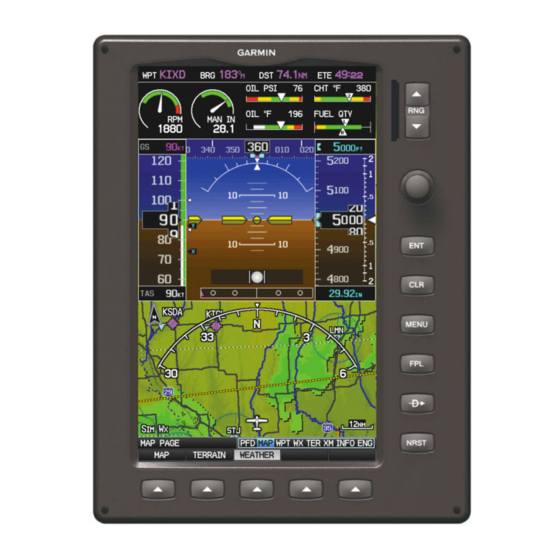
Page 29: G3X Single Display (Examples)
System Overview G3X SINGLE DISPLAY (EXAMPLES) In the single display, split-screen configuration, the Primary Flight Display (PFD) and the Multi Function Display (MFD) are displayed in split-screen mode on a single GDU. GDU 370 or 375 (XM) GDU 370 or 375 (XM) - Page 30 Magnetometer Heading Attitude Rate of Turn Heading Heading Slip/Skid Rate of Turn Slip/Skid G3X Dual ADAHRS Example Install NOTE: The G3X can support as many as three ADAHRS units. GEA 24 Engine/Airframe Unit Garmin G3X Pilot’s Guide 190-01115-00 Rev. K...
-
Page 31: G3X Dual Display (Examples)
A typical dual display panel would have the left GDU configured as a full-screen PFD and the right GDU configured as a full-screen MFD. The following is an example of a upgraded G3X panel using a GDU 370 and a GDU 375; however, two GDU 370s can be used if SiriusXM is not needed. - Page 32 Air Data Probe Computer GEA 24 Engine/Airframe Airspeed Unit Altitude GTP 59 Vertical Speed Temperature Probe AHRS Attitude Heading GMU 44/22 Rate of Turn Magnetometer Slip/Skid Heading G3X Upgraded Panel (Full-Screen) (GSU 25) Garmin G3X Pilot’s Guide 190-01115-00 Rev. K...
- Page 33 Vertical Speed GTP 59 Vertical Speed Temperature Engine/Airframe Probe Unit AHRS GMU 44/22 Attitude AHRS Magnetometer Heading Attitude Rate of Turn Heading Heading Slip/Skid Rate of Turn Slip/Skid G3X Upgraded Panel Dual ADAHRS 190-01115-00 Rev. K Garmin G3X Pilot’s Guide...
-
Page 34: Split-Screen Vs. Full-Screen Configurations
Slip/Skid Magnetometer Heading G3X Dual GSU 25 ADAHRS SPLIT-SCREEN VS. FULL-SCREEN CONFIGURATIONS Various combinations of split and full-screen configurations are available in systems with 2 or more GDUs. For example, a system with 2 GDUs (MFD and PFD1) can be... -
Page 35: External Navigators (Optional)
INTERNAL Softkey on the Active Flight Plan Page or Direct-To Page to make changes to the active flight plan from the G3X. Press the EXTERNAL Softkey to return to the external GPS navigator’s flight plan. When an external navigator is configured the internal GPS can still be used for VFR navigation. -
Page 36: Automatic Flight Control System (Optional)
MapMX. Refer to the G3X Installation Manual for more information. EXTERNAL GPS NAVIGATOR FAILURE In the event that all configured external GPS navigators fail, the G3X reverts to its internal VFR GPS for navigation and flight plan modifications. -
Page 37: Display Overview
NOTE: Refer to Appendix C for more information on SD Card use and data- bases. The G3X data card slot uses Secure Digital (SD) cards and is located on the upper right side of the display bezel(s). The SD card can be used for software updates, checklist files, flight data logging, exporting Track Logs/User Waypoints, and Importing/ Exporting Flight Plans. -
Page 38: G3X Controls
(the card should be flush with the face of the bezel). 2) To eject the card, gently press on the SD card to release the spring latch. SD Card Slot Display Bezel SD Card Slot 1.4 G3X CONTROLS Garmin G3X Pilot’s Guide 190-01115-00 Rev. K... - Page 39 Press and hold to capture screen shot FPL Key Press to display the Flight Plan Page Direct-To Key Press to activate the Direct-To function, enter a destination waypoint and establish a direct course to the selected destination 190-01115-00 Rev. K Garmin G3X Pilot’s Guide...
-
Page 40: System Power-Up
Current database information is displayed during power-up including valid operating dates, cycle number, and database type. When this information has been reviewed for currency (to ensure that no databases have expired), the pilot is prompted to continue. Garmin G3X Pilot’s Guide 190-01115-00 Rev. K... - Page 41 Pressing the ENT Key acknowledges this information. After acknowledgement of the database information, the pilot is prompted to acknowledge a data link weather advisory. Data link Weather Advisory Pressing the ENT Key acknowledges this information. 190-01115-00 Rev. K Garmin G3X Pilot’s Guide...
-
Page 42: System Operation
System Overview 1.6 SYSTEM OPERATION NOTE: The G3X display operation can be configured from the DSPL Page in Config Mode (refer to the G3X Installation Manual for more information). DISPLAY OPERATION NOTE: In a reversionary situation where failure occurs with all the GDUs... - Page 43 G3X Normal Mode (Optional Split-Screen PFD) • Full-Screen PFD/MFD Configuration (Reversionary Mode) In the event of a display failure, the G3X System automatically switches to reversionary (backup) mode. In reversionary mode, all flight information is presented on the remaining display in the split-screen configuration.
- Page 44 If a display failure occurs with the GDU 375, the WX and XM Pages will no longer be available since the XM receiver resides in the GDU 375. G3X Full-Screen Reversionary Mode (Failed PFD) • Multi-Display (Normal Mode) – In normal mode an example Multi-Display system includes a pilot-side PFD (PFD1), MFD, and co-pilot side PFD (PFD2).
-
Page 45: Pfd Display Configuration
4) Move the FMS Joystick to highlight the PFD2 Display Layout field. 5) Turn the FMS Joystick to highlight ‘Auto’, ‘Split’, or ‘PFD/MFD’. 6) Press the FMS Joystick, the CLR Key, the EXIT Softkey or the MENU Key to return to the previous page. 190-01115-00 Rev. K Garmin G3X Pilot’s Guide... -
Page 46: G3X System Annunciations
All instruments should be operational within one minute of power- up. If any instrument remains flagged, and it is not likely an installation related problem, the G3X should be serviced by a Garmin-authorized repair facility . PFD Initialization... - Page 47 (indicated by red ‘X’ flags over the corresponding flight instruments). If the G3X senses that the magnetic heading measurement is valid, but possibly outside of the internal accuracy limits, the numeric heading value on the PFD is displayed in yellow.
- Page 48 In installations that include multiple AHRS units (G3X supports up to three AHRS sources) if data from an AHRS source is lost the G3X will automatically switch sources, when a failure is detected. Reversionary sensor selection is annunciated in a window on the right side of the PFD.
- Page 49 System Overview Reversionary Sensor Window Dual AHRS 190-01115-00 Rev. K Garmin G3X Pilot’s Guide...
-
Page 50: Accessing System Functionality
NOTE: Flight Log and Track Log must be accessed from the MFD in a Multiple Display system. The G3X has a dedicated MENU Key. Press once to display a context-sensitive list of options for the page or the dedicated PFD. Press twice to display the Main Menu. -
Page 51: Data Entry
The FMS Joystick can be used for directly entering alphanumeric data into the G3X. In some instances, such as when entering an identifier, the G3X tries to predict the desired identifier based on the characters being entered. In this case, if the desired identifier appears, use the ENT Key to confirm the entry without entering the rest of the identifier manually. - Page 52 Turning the FMS Joystick counter- clockwise scrolls in the opposite direction. b) Use the FMS Joystick to move the cursor to the next placeholder in the field. Garmin G3X Pilot’s Guide 190-01115-00 Rev. K...
- Page 53 Selected Page Input Focus on Page Navigation Bar Active Page Title (Page Cursor Off) Input Focus on Current Page (Page Cursor On) Page Navigation (Split-Screen) 190-01115-00 Rev. K Garmin G3X Pilot’s Guide...
- Page 54 PFD Page (PFD) (split-screen) Traffic Page (TRF) Map Page (MAP) XM Audio Page (XM) (optional) Vertical Power (VP-X) (optional) Waypoint Page (WPT) Weather Page (WX) (optional) Info Page (INFO) Terrain Page (TER) Engine Page (ENG) Garmin G3X Pilot’s Guide 190-01115-00 Rev. K...
- Page 55 2) Turn or move the FMS Joystick to highlight ‘System Setup...’ and press the ENT Key. 3) Turn or move the FMS Joystick to highlight ‘Display’, and press the ENT Key. 4) Move the FMS Joystick to highlight the Traffic Page field. 190-01115-00 Rev. K Garmin G3X Pilot’s Guide...
- Page 56 • CTY (City)—name, bearing, and distance. • ATC (Air Route Traffic Control Center)—bearing, distance, and frequency. • FSS (Flight Service Station)—name, bearing, distance, frequency, and VOR (if applicable). • ASPC (Airspace)—name, time to entry (when applicable), and status. Garmin G3X Pilot’s Guide 190-01115-00 Rev. K...
- Page 57 Nearest Airport Weather (WX) (GDU 375) Nearest Cities (CTY) Nearest VORs (VOR) Nearest ARTCC (ATC) Nearest NDBs (NDB) Nearest FSS (FSS) Nearest Intersections (INT) Nearest Airspace (ASPC) Visual Reporting Point (VRP) (Atlantic) Nearest Pages (Split-Screen) 190-01115-00 Rev. K Garmin G3X Pilot’s Guide...
-
Page 58: Main Page Softkeys
When a softkey function is disabled, the softkey label is subdued (dimmed). Softkey Softkey Names (Displayed) Bezel Mounted Softkeys (Press) Softkeys (WPT Page) Garmin G3X Pilot’s Guide 190-01115-00 Rev. K... - Page 59 BARO MINIMUMS XX GAL BARO BACK MINIMUMS Allows the pilot to set or clear the barometric minimums altitude reminder BARO Allows the pilot to change the barometric setting BACK Returns to top-level softkeys 190-01115-00 Rev. K Garmin G3X Pilot’s Guide...
- Page 60 Allows the pilot to adjust the VOR course LOC CRS Allows the pilot to adjust the localizer course CODE Allows the pilot to enter the transponder code and displays the second-level CODE softkeys Garmin G3X Pilot’s Guide 190-01115-00 Rev. K...
- Page 61 With an autopilot configured, the #1 PFD Softkey becomes HDG/ROLL and the #5 PFD Softkey becomes ALT/PTCH. NOTE: Optional Integrated Autopilot Interface Softkeys are not available when a GMC 305 is operating as part of the AFCS system. 190-01115-00 Rev. K Garmin G3X Pilot’s Guide...
- Page 62 AP VNAV Selects/deselects altitude hold mode AP APPR Selects/deselects approach mode AP VS Selects/deselects vertical speed mode AP ALT Selects/deselects altitude hold mode Garmin G3X Pilot’s Guide 190-01115-00 Rev. K...
- Page 63 HIGH AWY BACK VFR MAP Softkey selected IFR MAP Displays IFR map information and softkeys TOPO Displays/removes topographical terrain shading SAT VIEW Displays/removes satellite imagery (above 20nm scale) BACK Returns to top-level softkeys 190-01115-00 Rev. K Garmin G3X Pilot’s Guide...
- Page 64 Displays METAR and TAF text (optional) WEATHER PAGE SOFTKEYS (OPTIONAL) SETUP ANIMATE INFO PAN MAP LEGEND PAN MAP Activates the map pointer for panning the map SETUP Select the weather source (XM or FIS-B). Garmin G3X Pilot’s Guide 190-01115-00 Rev. K...
- Page 65 Toggles terrain alerts on/off. VOL - BACK VOL + MUTE TRAFFIC PAGE SOFTKEYS (OPTIONAL GDL 39 OR GTS 800) INFO TREND FLT ID ALT MODE DISABLE BELOW NORMAL ABOVE UNREST BACK INFO STATIONS SETUP EXIT 190-01115-00 Rev. K Garmin G3X Pilot’s Guide...
- Page 66 Displays weather product status. XM AUDIO PAGE SOFTKEYS (OPTIONAL) VOLUME INFO CATEGORY CHANNEL FAVORITE INFO Displays XM Information CATEGORY Highlights the Category field CHANNEL Highlights the Channels field FAVORITE Displays a list of favorite channels Garmin G3X Pilot’s Guide 190-01115-00 Rev. K...
- Page 67 VOL + MUTE VOL - Decreases XM audio volume VOL + Increases XM audio volume MUTE Toggles XM audio on/off BACK Returns to top-level softkeys INFO PAGE SOFTKEY MESSAGES MESSAGES Displays system status messages 190-01115-00 Rev. K Garmin G3X Pilot’s Guide...
- Page 68 AUTO FLAPS DN ENG PAGE SOFTKEYS (EXAMPLE CONFIGURATION) NOTE: The Engine (ENG) Page softkeys displayed are dependant on the configuration. Refer to the G3X Installation Manual for information on configuring the Engine Page. Garmin G3X Pilot’s Guide 190-01115-00 Rev. K...
- Page 69 XX is an airframe specific partial fuel quantity (optional) XX GAL Sets fuel remaining to a partial tank quantity (i.e., filler neck tab) where XX is an airframe specific partial fuel quantity (optional) FUEL Returns to top-level softkeys 190-01115-00 Rev. K Garmin G3X Pilot’s Guide...
-
Page 70: Flight Planning Softkeys
Displays the available flight plans to import from the SD Card EXPORT Exports the selected flight plan EXIT Exits the Flight Plan Pages VERTICAL NAVIGATION (VNAV) PAGE SOFTKEYS CAPTURE EXIT CAPTURE Captures/cancels VNAV profile EXIT Exits the Flight Plan Pages Garmin G3X Pilot’s Guide 190-01115-00 Rev. K... -
Page 71: Nearest Page Softkeys
Internal system checking is performed to ensure the GPS receiver is providing accurate data to the GDU(s). The G3X GDUs can be configured to share GPS information (refer to the G3X Installation Manual for configuration information). For example, a GDU can be configured to share its GPS position, velocity, and time data with another GDU. - Page 72 • Lost Satellite Reception—the receiver is no longer tracking enough satellites for a 2D or 3D fix GPS Status, Position, and Data Fields (full-screen only) can be accessed from the Information Page. INFO Page (Split-Screen) Garmin G3X Pilot’s Guide 190-01115-00 Rev. K...
- Page 73 ENT Key. 4) After selecting your approximate position using the map pointer or entering an identifier, press the ENT Key. 5) The GPS Receiver will begin a new search based on the location entered. 190-01115-00 Rev. K Garmin G3X Pilot’s Guide...
-
Page 74: Position
‘Nearest Type’ using the ‘Change Nearest Type’ page menu option. By default the Nearest Type is set to ‘Automatic’, which will display the nearest large airport, enroute VOR, or city (in that order). Garmin G3X Pilot’s Guide 190-01115-00 Rev. K... - Page 75 Map Datum and Location Formats) is not set to a Lat/Lon format, a new menu option ‘Show/Hide Lat/Lon’ will appear on the INFO Page. Selecting ‘Show Lat/Lon’ allows simultaneous display of the current position in both the selected location format as well as Lat/Lon format. 190-01115-00 Rev. K Garmin G3X Pilot’s Guide...
-
Page 76: Data Fields And Layout (Full-Screen Mfd)
2) Turn or move the FMS Joystick to highlight ‘Select Page Layout’ and press the ENT Key. 3) Move the FMS Joystick to highlight the desired page layout option (1 Row, 2 Rows, 3 Rows), and press the ENT Key. Garmin G3X Pilot’s Guide 190-01115-00 Rev. K... -
Page 77: System Settings
If configured to ‘Set By Pilot’ in configuration mode, (refer to the Installation Manual for configuration information) the pilot can change the Flight ID and enable/disable ADS-B Transmit from the Transponder Setup Page. 190-01115-00 Rev. K Garmin G3X Pilot’s Guide... -
Page 78: Data Bar Fields
The content of the four data bar fields are independently configured by the user. The full-screen MFD and PFD Data Bar Fields are independently configured from each display. Data Bar Data Bar (Split-Screen) Garmin G3X Pilot’s Guide 190-01115-00 Rev. K... - Page 79 5) Turn the FMS Joystick to access the list of options, then turn or move the FMS Joystick to highlight the desired option and press the ENT Key. 6) To restore defaults, press the MENU Key. With ‘Restore Default’ highlighted, press the ENT Key. 190-01115-00 Rev. K Garmin G3X Pilot’s Guide...
- Page 80 ‘REV’ is displayed in yellow and ‘GPS’ is displayed in magenta in the upper left corner of the Data Bar when all external GPS navigation sources fail. External GPS Failure. Reverted to Internal GPS External GPS Navigation Failure Garmin G3X Pilot’s Guide 190-01115-00 Rev. K...
-
Page 81: Display
Backlight Intensity based on the aircraft’s instrument lighting bus voltage. With ‘Manual’ selected, the pilot can manually adjust the desired backlight intensity (1-10). After each power cycle the Backlight Intensity is set to the default, which is configurable. Refer to the G3X Installation Manual for more information. ‘EIS Display Location’... - Page 82 • User Selected—Enables the user to choose between ‘AUTO’ and ‘PFD’ via the Display Setup menu. For more information on how to enable the ‘EIS Display Location’ setting in Configuration Mode refer to the G3X Installation Manual. Garmin G3X Pilot’s Guide 190-01115-00 Rev. K...
- Page 83 Saving a Screenshot: 1) With screenshots enabled (see above), navigate to the desired screen. 2) Press and hold the MENU Key until the screen flashes indicating the screenshot was saved to the SD Card. 190-01115-00 Rev. K Garmin G3X Pilot’s Guide...
-
Page 84: Sound
(e.g., “Approaching Airspace” or “Arriving at Waypoint”). Alert Volume (e.g., terrain, traffic, autopilot, etc.) is set in configuration mode (refer to the G3X Installation Manual for more information). Sound Setup Page (Split-Screen) Adjusting XM and/or Message Volume: 1) Press the MENU Key twice to display the Main Menu. -
Page 85: Units
1) Press the MENU Key twice to display the Main Menu. 2) Turn or move the FMS Joystick to highlight ‘System Setup...’ and press the ENT Key. 3) Turn or move the FMS Joystick to highlight ‘Units’ and press the ENT Key. 190-01115-00 Rev. K Garmin G3X Pilot’s Guide... -
Page 86: Date & Time
FMS Joystick. 5) Press the FMS Joystick, the CLR Key, the EXIT Softkey or the MENU Key to return to the previous page. Date & Time Setup Page (Split-Screen) Garmin G3X Pilot’s Guide 190-01115-00 Rev. K... -
Page 87: Position
Buffer, Arrival Alarm, Next Waypoint Alarm, Proximity Alarm, and Fuel Tank Reminder Alarm. Changing alarm settings: 1) Press the MENU Key twice to display the Main Menu. 2) Turn or move the FMS Joystick to highlight ‘System Setup...’, and press the ENT Key. 190-01115-00 Rev. K Garmin G3X Pilot’s Guide... - Page 88 The Fuel Tank Timer (FUEL TIMER) data field option is the elapsed time since the ‘Fuel Tank’ Reminder alarm was last issued (HH:MM). Airspace Alarms (Split-Screen) Alarms (Full-Screen MFD) Nav Alarms (Split-Screen) Garmin G3X Pilot’s Guide 190-01115-00 Rev. K...
-
Page 89: Airport Criteria
5) Move the FMS Joystick to highlight the desired field and turn the FMS Joystick to select the desired option from the menu. Press the ENT Key if necessary to highlight the next field. 190-01115-00 Rev. K Garmin G3X Pilot’s Guide... - Page 90 4) Turn or move the FMS Joystick to select ‘Set Airport Criteria’, and then press the ENT Key. A window appears with the current settings. 5) Press the MENU Key. 6) With ‘Restore Default’ highlighted press the ENT Key. Garmin G3X Pilot’s Guide 190-01115-00 Rev. K...
-
Page 91: Section 2 Flight Instruments
Press the FMS Joystick if necessary to begin interaction with the Page Navigation Bar. 2) Turn the FMS Joystick to select the PFD Page. The following flight instruments and supplemental flight data are displayed on the PFD and/or PFD Page (split-screen). 190-01115-00 Rev. K Garmin G3X Pilot’s Guide... - Page 92 Flight Instruments Garmin G3X Pilot’s Guide 190-01115-00 Rev. K...
- Page 93 Zero Pitch Line Flap Indicator Current Track Indicator (Heading Strip) Navigation Source Current Heading Bearing 1 Information Window Selected Heading Bug Outside Air Temperature (OAT) Turn Rate Indicator Transponder Code Autopilot Status Box 190-01115-00 Rev. K Garmin G3X Pilot’s Guide...
-
Page 94: Airspeed Indicator
Flight Instruments AIRSPEED INDICATOR NOTE: The G3X Vspeed Reference values and Flaps Tick Mark values depend upon the aircraft’s specific system configuration and may vary from the examples discussed in this section. The Airspeed Indicator displays airspeed on a rolling number gauge using a moving tape. - Page 95 V . Using TAS instead of IAS causes V to be reduced at high altitudes. If configured, the G3X can calculate and display this reduction in V . A solid red band is used between the TAS adjusted V...
-
Page 96: Attitude Indicator
Angle of bank is indicated by the position of the pointer on the roll scale. Slip/skid is indicated by the location of the ball. Roll Pointer Roll Scale Horizon Line Aircraft Symbol Slip/Skid Indicator Land Representation Pitch Scale Sky Representation Roll Scale Zero Attitude Indicator Garmin G3X Pilot’s Guide 190-01115-00 Rev. K... -
Page 97: Altimeter
1) From the PFD Page (one display) or PFD (two display), press the ALT (or ALT/PTCH if the Integrated Autopilot Interface is configured) Softkey. 2) Press and hold the FMS Joystick. The current altitude is now displayed as the Selected Altitude. 190-01115-00 Rev. K Garmin G3X Pilot’s Guide... - Page 98 1) From the PFD Page (one display) or PFD (two display), press the BARO Softkey. 2) While stationary on the ground, press and hold the FMS Joystick. 3) Verify indicated altitude matches local field elevation. Garmin G3X Pilot’s Guide 190-01115-00 Rev. K...
- Page 99 1) From the PFD Page (one display) or PFD (two display), press the BARO Softkey. 2) Press the MINIMUMS Softkey. 3) Turn the FMS Joystick to display the desired alert altitude and press the ENT Key. 190-01115-00 Rev. K Garmin G3X Pilot’s Guide...
- Page 100 • After reaching the Selected Altitude, if the pilot flies outside the deviation band (±200 Feet of the Selected Altitude), the Selected Altitude changes to yellow text on a black background, flashes for 5 seconds, and an aural tone is generated. Garmin G3X Pilot’s Guide 190-01115-00 Rev. K...
- Page 101 3) Turn or move the FMS Joystick to highlight ‘Sound’, and press the ENT Key. 4) Move the FMS Joystick to highlight the Altitude Alert field, and select ‘On/ Off’ by turning the FMS Joystick. 190-01115-00 Rev. K Garmin G3X Pilot’s Guide...
-
Page 102: Vertical Speed Indicator (Vsi)
ILS frequency is tuned in the active NAV field of an external navigator. A green diamond acts as the VDI Indicator, like a glideslope needle on a conventional indicator. If a localizer frequency is tuned and there is no glideslope signal, “NO GS” is annunciated. Garmin G3X Pilot’s Guide 190-01115-00 Rev. K... - Page 103 GPS approach. The glidepath is analogous to the glideslope for GPS approaches supporting WAAS vertical guidance (LNAV+V, L/VNAV, LPV). The Glidepath Indicator appears on the G3X as a magenta diamond. If the approach type downgrades past the final approach fix (FAF), “NO GP” is annunciated.
-
Page 104: Horizontal Situation Indicator (Hsi)
The HSI also presents course deviation, bearing, and navigation source information. The Selected Heading is shown to the left of the HSI The light blue bug on the compass rose corresponds to the Selected Heading. Garmin G3X Pilot’s Guide 190-01115-00 Rev. K... - Page 105 To/From Indicator Current Track Indicator Aircraft Symbol Course Pointer Lateral Deviation Scales Navigation Source Selected Heading Bug Course Deviation Indicator Course Deviation & To/From (CDI) Indicator Rotating Compass Rose Horizontal Situation Indicator (HSI) 190-01115-00 Rev. K Garmin G3X Pilot’s Guide...
- Page 106 Flight Instruments HSI ANNUNCIATIONS NOTE: Some or all HSI annunciations may appear in the four quadrants of the G3X HSI depending on the external navigator(s) configured (i.e., SL30 Nav/Comm Transceiver and/or the GTN or GNS Series Units). VFR CDI Scales: ‘1’...
- Page 107 • GPS is the bearing source and an the tuned VOR station active waypoint is not selected Bearing Bearing Pointer 2 Pointer 1 Bearing 1 Information Window Bearing 2 Information Window -Identifier -Identifier -Bearing Source -Distance HSI with Bearing Pointers 190-01115-00 Rev. K Garmin G3X Pilot’s Guide...
- Page 108 Scale The CDI is capable of displaying two sources of navigation: GPS or NAV (VOR, localizer) depending on the external navigator(s) configured (refer to the G3X Installation Manual for more information). Color indicates the current navigation source: magenta (for GPS) or green (for VOR and LOC). The full-scale limits for the CDI are defined by a GPS-derived distance when coupled to GPS.
- Page 109 Pilot’s Guide, or the GTN or GNS Series Pilot’s Guides) for more information. external navigator is configured the internal GPS can still be used for VFR navigation. NOTE: The G3X internal GPS flight plan is only for VFR use. 190-01115-00 Rev. K...
- Page 110 Navigator 2 Navigator 2 Navigator (e.g., if the external navigator is a GNS 430, press the CDI Key on the GNS 430 to toggle between GPS1 and LOC1 or GPS2 and LOC2) CDI Source Garmin G3X Pilot’s Guide 190-01115-00 Rev. K...
- Page 111 G loads. When in the auto display mode, the G-meter will automatically be displayed when an unusual attitude is sensed (i.e., greater than +/- 65° roll or +30°/-20° pitch). Refer to the G3X installation manual for more information on configuring the G-meter.
- Page 112 While in ‘Auto Trk/Hdg’ the HSI will remain heading-based when the aircraft is on the ground or when the autopilot is in HDG mode. Refer to the G3X installation manual for more information on configuring the HSI Orientation.
- Page 113 2) Press the MORE Softkey. 3) Move the FMS Joystick to highlight PITCH OFFSET. 4) Turn the FMS Joystick to select the desired setting. Aircraft Symbol showing pitch offset. Pitch Attitude offset angle Pitch Attitude Offset 190-01115-00 Rev. K Garmin G3X Pilot’s Guide...
- Page 114 Press the INTERNAL Softkey on the Active Flight Plan Page or the Direct-to Page, to temporarily allow flight planning through the G3X using the internal GPS flight plan when an external GPS Navigator is configured. Press the EXTERNAL Softkey to return to the external GPS navigator’s flight plan.
- Page 115 ‘REV’ is shown in yellow in the upper left corner of the Data Bar as well as the lower left quadrant of the HSI. External Failure. Reverted to Internal REV: External Navigation Source failed. Reverted to internal VFR GPS for navigation. External GPS Navigation Failure 190-01115-00 Rev. K Garmin G3X Pilot’s Guide...
- Page 116 CDI scale. lewing The G3X will automatically slew the LOC course pointer to the correct final approach course when an ILS, LOC, BC, LDA, or SDF approach is active in the external navigator and the appropriate CDI and navigation source are selected on the G3X.
-
Page 117: Trim And Flap Position Indicators (Optional)
ENG page. Elevator Trim, Aileron Trim, Rudder Trim, and Flap Position indicators can be configured from the Engine/Airframe Input Configuration Page in Configuration Mode. Refer to the G3X Installation Manual for more information. 190-01115-00 Rev. K Garmin G3X Pilot’s Guide... -
Page 118: Heading Strip And Turn Rate Indicator
4 deg/sec, an arrowhead appears at the end of the magenta trend vector and the prediction is no longer valid. Turn Rate Indicator (Standard Rate Tick Marks) Turn Rate Trend Vector Heading Strip Current Heading Current Track Indicator Selected Heading Heading Strip/Turn Rate Indicator Garmin G3X Pilot’s Guide 190-01115-00 Rev. K... -
Page 119: Obs Mode
3) Turn the FMS Joystick to select the desired course to/from the waypoint. 4) To cancel OBS Mode and return to automatic waypoint sequencing, press the MENU Key, with ‘Release Hold’ highlighted, press the ENT Key. 190-01115-00 Rev. K Garmin G3X Pilot’s Guide... -
Page 120: Supplemental Flight Data
1) Press the OBS Key on the external navigator. The ‘Set OBS and Hold’ Active Flight Plan Page menu option is now available. 2) Turn the FMS Joystick on the G3X to select the desired course to/from the waypoint. Syncing to the current aircraft location (without external GPS... -
Page 121: Wind Data
G3X installations that include a GAP 26 and a GSU 25, Angle of Attack information can be displayed on the PFD. Refer to the G3X Installation Manual for the Angle of Attack Calibration procedure. During Angle of Attack Calibration Stall Warning AOA, Caution Alert AOA, Minimum Visible AOA, and Approach Target AOA are defined. - Page 122 When AOA is below the calibrated Minimum Visible AOA threshold, the angle of attack gauge is not displayed. Angle of Attack Angle of Attack (AOA) Stall Warning AOA (Flashes) Caution Alert Approach Target AOA Minimum Visible AOA Angle of Attack Display (AOA) Garmin G3X Pilot’s Guide 190-01115-00 Rev. K...
-
Page 123: Vertical Navigation (Vnav)
The VNAV feature does not take into account any changes in ground speed that occur during the transition from level flight to descent or climb. At 200 ft above the target altitude, the “Approaching Target Altitude” message appears, and the VNAV indicator disappears from the PFD. 190-01115-00 Rev. K Garmin G3X Pilot’s Guide... -
Page 124: Using The Vnav Feature
2) Turn the FMS Joystick to select the Vertical Navigation Page. 3) Press the FMS Joystick to activate the cursor. 4) Enter the desired profile into the fields, and press the EXIT Softkey. Garmin G3X Pilot’s Guide 190-01115-00 Rev. K... - Page 125 1) From the full-screen PFD and/or the split-screen PFD Page, press the MENU Key. 2) Move the FMS Joystick to highlight the VNAV Indicator field. 3) Turn the FMS Joystick to highlight ‘On’ or ‘Off’. 190-01115-00 Rev. K Garmin G3X Pilot’s Guide...
- Page 126 4) Turn or move the FMS Joystick to highlight ‘Cancel VNAV Capture’ and press the ENT Key. 1) Enter a valid VNAV profile and begin navigation. 2) From the VNAV Page, press (deselect) the CAPTURE Softkey. Garmin G3X Pilot’s Guide 190-01115-00 Rev. K...
-
Page 127: Section 3 Engine Indication System
SECTION 3 ENGINE INDICATION SYSTEM 3.1 EIS DISPLAY & ENG PAGE NOTE: The display of the G3X Engine Indication System depends upon the current configuration and may vary from the examples discussed in this sec- tion. The G3X Engine Indication System (EIS) displays critical engine, electrical, and other system parameters on the top portion of the display (split-screen and/or full-screen MFD). - Page 128 Example Engine (ENG) Page Configuration - TEMPS Softkey Selected (Split-Screen) Example Engine (ENG) Page Configuration- AUX Softkey Selected (Split-Screen) Garmin G3X Pilot’s Guide 190-01115-00 Rev. K...
- Page 129 Displays fuel pressure 13 18 Voltmeter Displays the main bus voltage 14 29 Ammeter Displays the battery load in amperes 15 30 Total Hours (HOURS) Refer to G3X Installation Manual for 16 31 more information. 190-01115-00 Rev. K Garmin G3X Pilot’s Guide...
- Page 130 If sensory data to an instrument becomes invalid or unavailable, a red “X” is displayed across the instrument. Garmin G3X Pilot’s Guide 190-01115-00 Rev. K...
-
Page 131: Eng Page Softkeys (Example Configuration)
ENG PAGE SOFTKEYS (EXAMPLE CONFIGURATION) NOTE: The Engine (ENG) Page softkeys displayed are dependant on the configuration. Refer to the G3X Installation Manual for information on configuring the Engine Page. If the Engine Page information configured exceeds one page, additional engine gauges may be distributed among the 1st, 2nd, and 3rd softkeys as required. - Page 132 Peak Temperature Cylinder to Peak Leaning to First Peak (ENG Page - Full-Screen MFD) A ‘ NOTE: +’ (DEGT) value indicates that the current temperature is greater than the previously detected peak. Garmin G3X Pilot’s Guide 190-01115-00 Rev. K...
- Page 133 DTIT) is displayed in place of the normal temperature number in light blue text. Difference Between Present and Peak Temperature Cylinder with the Cylinder Peak Temperature Closest to Temperature Its Peak Value Engine Instrument Display (Split-Screen) 190-01115-00 Rev. K Garmin G3X Pilot’s Guide...
- Page 134 Lean Assist Mode - ENG Page (Split-Screen) If Turbine Inlet Temperature (TIT) inputs are configured, the first and last TIT to peak are not identified. Lean Assist Mode - Turbine Inlet Temperature (ENG Page) Garmin G3X Pilot’s Guide 190-01115-00 Rev. K...
-
Page 135: Fuel Calculator (Optional)
WARNING: The G3X Fuel Calculator and/or Fuel Range Rings are NOT intended to be relied upon as the primary fuel indicator(s), and does not relieve the pilot from the responsibility of proper flight planning. G3X fuel calculations do not use the aircraft fuel quantity indicators and are calculated from the last time the fuel was reset. - Page 136 Fuel Calculator (Split-Screen) Fuel Calculator (Full-Screen MFD) Garmin G3X Pilot’s Guide 190-01115-00 Rev. K...
-
Page 137: Fuel Calculator Softkeys
XX is an airframe specific partial fuel quantity (optional) XX GAL Sets fuel remaining to a partial tank quantity (i.e., filler neck tab) where XX is an airframe specific partial fuel quantity (optional) FUEL Returns to top-level softkeys 190-01115-00 Rev. K Garmin G3X Pilot’s Guide... -
Page 138: Confirming Fuel Quantity
XX GAL Sets fuel remaining to a partial tank quantity (i.e., filler neck tab) where XX is an airframe specific partial fuel quantity (optional) DONE Returns to top-level softkeys Garmin G3X Pilot’s Guide 190-01115-00 Rev. K... - Page 139 Resetting Fuel Remaining to partial fuel quantities (optional): Press Softkey #3 or #4 (XX GAL); this resets fuel remaining to a partial tank quantity (i.e., filler neck tab). XX is the airframe specific partial fuel quantity (if configured). 190-01115-00 Rev. K Garmin G3X Pilot’s Guide...
-
Page 140: Cas Messages (Optional)
3.4 CAS MESSAGES (OPTIONAL) The CAS messages displayed depend upon the current configuration, and will vary from the examples listed below. Refer to the G3X Installation Manual for more information on configuring CAS messages (if applicable). CAS Messages are grouped by criticality (warning, caution, advisory). The color of the message is based on its urgency and on required action: •... - Page 141 If less than four CAS Messages are configured for the system, the CAS Messages are displayed to the right of the Airspeed Indicator and the Check Alerts Triangle is not displayed. CAS Warning Example 190-01115-00 Rev. K Garmin G3X Pilot’s Guide...
- Page 142 Blank Page Garmin G3X Pilot’s Guide 190-01115-00 Rev. K...
-
Page 143: Section 4 Cns Interface
CNS Interface SECTION 4 CNS INTERFACE 4.1 AUTO-TUNING FREQUENCIES (OPTIONAL) NOTE: Refer to the G3X Installation Manual for more information on the G3X optional communication interfaces. Frequencies can be automatically tuned from the following: • Map Page • Nearest Airport Weather Page •... - Page 144 4) Press the ENT Key to load the frequency into the standby field of the SL40. If the frequency has an * (additional information available) next to it, press the ENT Key a second time with ‘Tune’ highlighted. Frequency with Additional Information (Split-Screen) Garmin G3X Pilot’s Guide 190-01115-00 Rev. K...
- Page 145 3) Press the ENT Key to load the frequency into the standby field of the SL40. If the frequency has an * (additional information available) next to it, press the ENT Key a second time with ‘Tune’ highlighted. 190-01115-00 Rev. K Garmin G3X Pilot’s Guide...
-
Page 146: Remote Transponder Interface (Optional)
PFD. All trim gauges are available from the ENG page. The G3X is capable of interfacing with several remote transponders providing Mode S interrogation and reply capabilities. Selective addressing or Mode Select (Mode S) capability includes the following features: •... - Page 147 LOC CRS IDENT CODE MODE BACK STBY / GND SET ID BACK IDENT CODE BACK IDENT Sends a distinct identity indication to Air Traffic Control (ATC). CRS (subdued) A navigation source is not selected 190-01115-00 Rev. K Garmin G3X Pilot’s Guide...
- Page 148 SET ID Allows the pilot to set the Flight ID. (The Flight ID must be configured to ‘Set By Pilot’ for the SET ID softkey to be displayed). BACK Returns to previous level softkeys Garmin G3X Pilot’s Guide 190-01115-00 Rev. K...
-
Page 149: Transponder Mode Selection
Mode A and Mode S replies, but Mode C altitude reporting is inhibited. In ON Mode, a green ON indication and transponder code appear in the mode field of the Transponder Data Box. 190-01115-00 Rev. K Garmin G3X Pilot’s Guide... -
Page 150: Entering A Transponder Code
2) Press the CODE Softkey. A Transponder Code Box appears with the cursor on the first digit in the code. 3) Enter the desired code using the FMS Joystick and press the ENT Key. Transponder CODE Code Entry Softkey Transponder Code Entry (Split-Screen PFD Page) Garmin G3X Pilot’s Guide 190-01115-00 Rev. K... -
Page 151: Ident Function
Transponder Data Box, if the ADS-B Out broadcast has been manually disabled or if the transponder does not have the required GPS data. Transponder is not broadcasting ADS-B Out data NO ADS-B (Split-Screen PFD Page) 190-01115-00 Rev. K Garmin G3X Pilot’s Guide... -
Page 152: Flight Id Reporting
CNS Interface FLIGHT ID REPORTING NOTE: The Flight ID must be configured to ‘Set By Pilot’ in Configuration Mode for the SET ID Softkey to appear. Refer to the G3X Installation Manual for more information. Entering a Flight ID: 1) From the full-screen PFD and/or the split-screen PFD Page, press the XPDR Softkey. -
Page 153: Section 5 Gps Navigation
NOTE: The compass arc is not available in ‘North Up’ map orientation. A compass arc representing the aircraft’s ground track, appears by default on the Map Page. The route line represents the course. Compass Arc Route Line Compass Arc (Map Page) 190-01115-00 Rev. K Garmin G3X Pilot’s Guide... -
Page 154: Using Map Displays
WARNING: The G3X map displays are to be used for situational awareness only. Map displays are used extensively in the G3X to provide situational awareness in flight. Most G3X maps can display the following information: • Airports, NAVAIDs, airspaces, airways, land data (highways, cities, lakes, rivers, borders, etc.) with names... -
Page 155: Map Page Setup
Turn or move the FMS Joystick to highlight ‘North Up’, ‘Track Up’, or ‘DTK Up’, and press the ENT Key. a) Move the FMS Joystick to highlight the ‘North Up Above’ field. b) Turn the FMS Joystick to access a list of available range options. 190-01115-00 Rev. K Garmin G3X Pilot’s Guide... - Page 156 Runway Extension line Runway Number Runway Extensions and Numbers (Map Page) Garmin G3X Pilot’s Guide 190-01115-00 Rev. K...
- Page 157 4) Move the FMS Joystick to highlight the desired feature. 5) Turn the FMS Joystick to access a list of options for each feature (On/Off, Auto, range settings, or text size). 190-01115-00 Rev. K Garmin G3X Pilot’s Guide...
- Page 158 7) Press the FMS Joystick, the CLR Key, or the EXIT Softkey to return to the Map Page with the changed settings. Map Setup Page (Airspace Category) Map Setup Page (Airspace Category - Atlantic) Garmin G3X Pilot’s Guide 190-01115-00 Rev. K...
-
Page 159: Map Range
(Split-Screen) AUTO ZOOM Auto Zoom allows the G3X to change the map display range to the smallest range clearly showing the active waypoint. Auto Zoom can be overridden by adjusting the range and remains that way until the active waypoint changes, a terrain or traffic alert occurs, or the aircraft takes off. -
Page 160: Map Panning
Map Pointer position, a green arrow will appear in the information box. Turning the FMS Joystick will cycle through the list of map features present at that position. Garmin G3X Pilot’s Guide 190-01115-00 Rev. K... - Page 161 2) Press the ENT Key to display the review page for the highlighted feature. 3) Press the FMS Joystick, the CLR Key, or the ENT Key to exit the review page and return to the Map Page showing the selected waypoint. 190-01115-00 Rev. K Garmin G3X Pilot’s Guide...
-
Page 162: Fuel Range Ring
WARNING: The G3X Fuel Calculator and/or Fuel Range Rings are NOT intended to be relied upon as the primary fuel indicator(s), and does not relieve the pilot from the responsibility of proper flight planning. G3X fuel calculations do not use the aircraft fuel quantity indicators and are calculated from the last time the fuel was reset. -
Page 163: Measuring Bearing And Distance
Elevation at the current pointer position is also displayed. Pressing the ENT Key changes the starting point for measuring. 4) To exit the Measure Bearing/Distance option, press the FMS Joystick; or select ‘Stop Measuring’ from the Page Menu and press the ENT Key. 190-01115-00 Rev. K Garmin G3X Pilot’s Guide... -
Page 164: Topography
3) Turn the FMS Joystick to highlight the ‘Map’ Category from the horizontal list. 4) Move the FMS Joystick to highlight the ‘Topo Shading’ field. 5) Turn the FMS Joystick to select ‘On’ or ‘Off’, and press the ENT Key. Garmin G3X Pilot’s Guide 190-01115-00 Rev. K... -
Page 165: Satellite View
3) Turn the FMS Joystick to highlight the ‘Map’ Category from the horizontal list. 4) Move the FMS Joystick to highlight the ‘Satellite View’ field. 5) Turn the FMS Joystick to select ‘On’ or ‘Off’, and press the ENT Key. 190-01115-00 Rev. K Garmin G3X Pilot’s Guide... -
Page 166: Map Page Traffic
The background symbols (such as highways, cities, rivers, and smaller lakes) are removed from the map. 2) Press the CLR Key again. ‘CLEAR-2’ appears below the map range and airspace boundary detail is removed from the map. Garmin G3X Pilot’s Guide 190-01115-00 Rev. K... - Page 167 4) Move the FMS Joystick to highlight the ‘Detail Level’ field. 5) Turn the FMS Joystick to select the desired detail level (‘Most’, ‘More’, ‘Normal’, ‘Less’, or ‘Least’), and press the ENT Key. 190-01115-00 Rev. K Garmin G3X Pilot’s Guide...
-
Page 168: Airways
5.3 AIRWAYS WARNING: Do not use the approach information provided by the VFR navigation database residing within the G3X as a means of navigating any instrument approach. The G3X VFR navigation database is limited to pres- ent only the waypoints for the final approach leg of a published procedure. - Page 169 Calculated -MEA Radial -Airway Name -Endpoints -Distance Calculated Radial Reviewing Airway Information (Map Page) (Split-Screen) 5) Press the ENT Key to display the review page for the airway. 190-01115-00 Rev. K Garmin G3X Pilot’s Guide...
-
Page 170: Waypoints
The Waypoint Page allows the pilot to review airport information, runway information, frequencies, instrument procedures, airport directory information, and weather information. The pilot can manually enter the identifier or the G3X will choose the most appropriate identifier based on the current position and phase of flight. - Page 171 -Lat/Long (Full) -Bearing/Distance INFO Softkey Selected Waypoint Page (INFO Softkey Selected) (Split-Screen) Runway Information -Designation -Length/Width -Surface -Lighting Showing -Traffic Pattern Selected -Wind (Full) Waypoint RUNWAY Softkey Selected Waypoint Page (RUNWAY Softkey Selected) (Split-Screen) 190-01115-00 Rev. K Garmin G3X Pilot’s Guide...
- Page 172 (turning it counter-clockwise brings up the waypoint selection submenu - press the CLR Key or the FMS Joystick to remove it), or move the FMS Joystick to select the facility name, or city field. 4) Press the ENT Key. Garmin G3X Pilot’s Guide 190-01115-00 Rev. K...
- Page 173 7) Move the FMS Joystick to place the cursor in the ‘Runway’ Box, on the runway designator. Runways Box (Waypoint Page) 8) Turn the FMS Joystick to display the desired runway (if more than one) for the selected airport. 190-01115-00 Rev. K Garmin G3X Pilot’s Guide...
- Page 174 *. Additional Frequency Information (Waypoint Page) 4) Press the ENT Key to view the Additional Information Window. 5) To remove the window, press the FMS Joystick, ENT Key, or CLR Key. Garmin G3X Pilot’s Guide 190-01115-00 Rev. K...
-
Page 175: Nearest Information
‘View Departure Airport’, and press the ENT Key. NEAREST INFORMATION The G3X provides a NRST Key which gives the pilot quick access to nearest airport, weather, VOR, NDB, intersection, user waypoint, city, ARTCC, FSS, and airspace information. If none are available, “None Within 200 NM” is displayed. - Page 176 3) Press the ENT Key. The Airport Criteria Window is displayed. 4) Move the FMS Joystick to select the desired criteria to be defined. 5) Turn the FMS Joystick to select the desired option. 6) Press the ENT Key. Garmin G3X Pilot’s Guide 190-01115-00 Rev. K...
-
Page 177: Weather Information
Airport Weather is not available, “None Within 200 NM” is displayed. 3) Press the FMS Joystick to highlight the first airport in the nearest airport weather list. Turn or move the FMS Joystick to highlight the desired airport weather. 190-01115-00 Rev. K Garmin G3X Pilot’s Guide... -
Page 178: Intersections
2) Turn the FMS Joystick to select the Nearest Intersections Page. 3) Press the FMS Joystick to activate the cursor. 4) Turn or move the FMS Joystick to highlight the desired intersection. 5) Press the ENT Key to display the Intersection Information Page. Garmin G3X Pilot’s Guide 190-01115-00 Rev. K... -
Page 179: Ndbs
The list only includes VORs that are within 200nm. If there are no VORs in the list, text indicating that there are no nearest VORs is displayed. If there are no nearest VORs in the list, the information and frequency fields are dashed. 190-01115-00 Rev. K Garmin G3X Pilot’s Guide... -
Page 180: User Waypoints
5) Press the ENT Key to display the VOR Information Page. USER WAYPOINTS The G3X can create and store up to 3,000 user-defined waypoints. Once a waypoint has been created, it can be renamed, deleted, or moved. Creating user waypoints:... - Page 181 Move the FMS Joystick to highlight the Symbol. b) Turn the FMS Joystick to access the ‘Select Symbol’ Menu. c) Turn or move the FMS Joystick to highlight the desired symbol from the menu, and press the ENT Key. 190-01115-00 Rev. K Garmin G3X Pilot’s Guide...
- Page 182 New Waypoint Window New Waypoint Window (POSITION Softkey Selected) (REF WPTS Softkey Selected) (Split-Screen) (Split-Screen) 6) With ‘Done’ highlighted, press the ENT Key. Garmin G3X Pilot’s Guide 190-01115-00 Rev. K...
- Page 183 ENT Key. If deleting all user waypoints, go to Step 4. 3) Highlight a User Waypoint in the User Waypoint List, or enter a waypoint in the User Waypoint field. 4) Press the MENU Key. User Waypoints Page Menu 190-01115-00 Rev. K Garmin G3X Pilot’s Guide...
-
Page 184: Automatic Waypoint Selection
The automatic selection will not resume until such time that the manually entered waypoint and the automatically selected waypoint coincide (does not apply if the CHART Softkey is selected). To manually return to Automatic Waypoint Selection, highlight the identifier and press the CLR Key. Garmin G3X Pilot’s Guide 190-01115-00 Rev. K... -
Page 185: Airspace
5) Press the FREQS Softkey (if available) to display frequency and additional airport information similar to the Waypoint Information Page. Nearest Airspace Page Airspace Information Page (Split-Screen) (Split-Screen) The Full-Screen Display will also show a map with the nearest airspace highlighted. 190-01115-00 Rev. K Garmin G3X Pilot’s Guide... -
Page 186: Airspace Alert Messages
• Inside Airspace—Within the boundaries of the airspace SMART AIRSPACE ™ Smart Airspace shows airspace at and immediately surrounding the aircraft’s ™ current altitude in bold. Airspaces at all other altitudes are de-emphasized. De-emphasized Bold Airspace Airspace Smart Airspace ™ Garmin G3X Pilot’s Guide 190-01115-00 Rev. K... -
Page 187: Direct-To Navigation Using The G3X
GPS Navigation 5.6 DIRECT-TO NAVIGATION USING THE G3X NOTE: The G3X Direct-to Key is disabled while using an external GPS naviga- tor. Press the INTERNAL Softkey on the Direct-to Page to make changes to the active flight plan from the G3X. Press the EXTERNAL Softkey to return to the external GPS navigator’s flight plan. - Page 188 (RECENT WPTS), nearest airports (NRST APTS), and flight plan waypoints (FPL WPTS). 4) Move the FMS Joystick to select the desired waypoint. 5) Press the ENT Key. 6) With ‘Activate’ highlighted, press the ENT Key. Garmin G3X Pilot’s Guide 190-01115-00 Rev. K...
- Page 189 3) If the pointer is placed on an existing airport, NAVAID, or user waypoint, the waypoint name is highlighted. 4) Press the Direct-to Key to display the Direct-to Window with the selected point entered as the direct-to destination. 190-01115-00 Rev. K Garmin G3X Pilot’s Guide...
- Page 190 3) Move the FMS Joystick to highlight ‘Stop Navigation’ or ‘Resume Flight Plan’ if a flight plan was active. 4) Press the ENT Key. If a flight plan is still active, the G3X resumes navigating the flight plan. 1) Press the FPL Key.
-
Page 191: Section 6 Flight Planning
The active flight plan is erased when the destination is reached and the system is turned off. When storing flight plans with an approach, the G3X uses the waypoint information from the current database to define the waypoints. If the database is changed or updated, the G3X automatically updates the information if the procedure has not been modified. -
Page 192: Flight Plan Data Fields
5) Turn the FMS Joystick to access the list of available Data Fields. 6) Turn or Move the FMS Joystick to highlight the desired option from the list and press the ENT Key. Garmin G3X Pilot’s Guide 190-01115-00 Rev. K... -
Page 193: Flight Planning
Data Field Selection (Active Flight Plan Page) Viewing fuel remaining at each waypoint: From the Active Flight Plan Page, move the FMS Joystick (right or left) to quickly change the third data field to Fuel Remaining (FUEL REM). 190-01115-00 Rev. K Garmin G3X Pilot’s Guide... -
Page 194: Manually Switching Between Internal And External Flight Plan Sources
Press the INTERNAL Softkey on the Active Flight Plan Page or the Direct-to Page, to temporarily allow flight planning through the G3X using the internal GPS flight plan when an external GPS Navigator is configured. Press the EXTERNAL Softkey to return to the external GPS navigator’s flight plan. -
Page 195: Failure Of The External Gps Navigation Source
HSI. External GPS Failure. Reverted to Internal GPS REV: External Navigation Source failed. Reverted to internal VFR GPS for navigation. External GPS Navigation Failure 190-01115-00 Rev. K Garmin G3X Pilot’s Guide... -
Page 196: Flight Plan Creation Using The G3X
The active flight plan is listed on the Active Flight Plan Page. It is the flight plan to which the G3X is currently providing guidance, and is shown on the navigation maps. Stored flight plans are listed on the Flight Plan List Page, and are available for activation (becomes the active flight plan). - Page 197 6) Repeat step numbers 3 and 4 to enter each additional flight plan waypoint. 7) When all waypoints have been entered, press the FMS Joystick to remove the cursor. Creating a stored flight plan using the G3X: 1) Press the FPL Key. 2) If an external navigator is configured, press the INTERNAL Softkey.
-
Page 198: Flight Plan Storage Using The G3X
Flight Planning 6.3 FLIGHT PLAN STORAGE USING THE G3X The G3X can store up to 50 flight plans. The active flight plan is erased when another flight plan is activated. Details about each stored flight plan can be viewed on the Flight Plan List Page Viewing information about a stored flight plan: 1) Press the FPL Key. -
Page 199: Flight Plan Activation Using The G3X
Flight Planning 6.4 FLIGHT PLAN ACTIVATION USING THE G3X Activating a stored flight plan erases the active flight plan and replaces it with a copy of the flight plan being activated. Inverting a stored flight plan reverses the waypoint order, erases the active flight plan, and replaces it with the flight plan being activated (the stored flight plan is not changed). -
Page 200: Flight Plan Editing
3) Press the FMS Joystick to activate the cursor. 4) Using the FMS Joystick select the point in the flight plan before which to add the new waypoint. The new waypoint is placed directly in front of the highlighted waypoint. Garmin G3X Pilot’s Guide 190-01115-00 Rev. K... - Page 201 5) With the desired flight plan leg highlighted (blue), press the ENT Key (the flight plan leg turns magenta). This will split the flight plan leg. 6) Using the FMS Joystick, drag the flight plan leg to highlight the desired waypoint to be added. 190-01115-00 Rev. K Garmin G3X Pilot’s Guide...
-
Page 202: Editing Flight Plan Speed, Fuel, And/Or Name
3) Press the FMS Joystick to activate the cursor, and move the FMS Joystick to highlight the ‘Plan Fuel’ field. 4) Using the FMS Joystick, enter the desired plan flow, and press the ENT Key. Garmin G3X Pilot’s Guide 190-01115-00 Rev. K... - Page 203 3) Move the FMS Joystick to the ‘Plan Speed’ field. 4) Using the FMS Joystick, enter the desired speed, and press the ENT Key. 5) Repeat steps 3 and 4 for ‘Plan Fuel’, and press the DONE Softkey. 190-01115-00 Rev. K Garmin G3X Pilot’s Guide...
- Page 204 3) Move the FMS Joystick to highlight the Flight Plan Name field. 4) Using the FMS Joystick, enter the flight plan name, and press the ENT Key. Editing the Saved Flight Plan Name Garmin G3X Pilot’s Guide 190-01115-00 Rev. K...
-
Page 205: Copying Flight Plans
Flight Planning COPYING FLIGHT PLANS The G3X allows copying a flight plan into a new flight plan memory slot, allowing editing, etc., without affecting the original flight plan. This can be used to duplicate an existing stored flight plan for use in creating a modified version of the original stored flight plan. - Page 206 Waypoint’. The ‘Remove XXXXX From Flight Plan?’ window is displayed. Remove Waypoint Window 5) With ‘Yes’ highlighted, press the ENT Key. To cancel the request, press the CLR Key, the FMS Joystick, or highlight ‘No’ and press the ENT Key. Garmin G3X Pilot’s Guide 190-01115-00 Rev. K...
-
Page 207: Inverting A Flight Plan
4) Press the MENU Key, highlight ‘Invert Flight Plan?’, and press the ENT Key. 5) With ‘Yes’ highlighted, press the ENT Key. To cancel the request, press the CLR Key, the FMS Joystick, or highlight ‘No’ and press the ENT Key. 190-01115-00 Rev. K Garmin G3X Pilot’s Guide... -
Page 208: Importing/Exporting Flight Plans
NAVIGATOR CONFIGURED) WARNING: Do not use the approach information provided by the VFR navigation database residing within the G3X as a means of navigating any instrument approach. The G3X VFR navigation database is limited to pres- ent only the waypoints for the final approach leg of a published procedure. -
Page 209: Selecting An Approach
Loading an approach from the active or saved flight plan page: 1) Press the FPL Key. 2) Turn the FMS Joystick to display the Active Flight Plan Page or Saved Flight Plan Page. 190-01115-00 Rev. K Garmin G3X Pilot’s Guide... - Page 210 CLR Key or the FMS Joystick. 1) With an approach loaded on the Active Flight Plan Page, press the MENU Key. 2) Turn or move the FMS Joystick to highlight ‘Activate Approach’, and press the ENT Key. Garmin G3X Pilot’s Guide 190-01115-00 Rev. K...
- Page 211 2) Turn the FMS Joystick to display the Active Flight Plan Page or Saved Flight Plan Page. 3) Press the RMV APPR Softkey; or press the MENU Key, highlight ‘Remove Approach’ by turning or moving the FMS Joystick, and press the ENT Key. 190-01115-00 Rev. K Garmin G3X Pilot’s Guide...
-
Page 212: Activating Vectors-To-Final
After an approach has been activated, the VECTORS Softkey is used when being vectored to the final approach course by Air Traffic Control (ATC). If the VECTORS Softkey is pressed, the G3X creates an extension of the final course, beyond the final approach waypoint in the database (final approach fix [FAF]). On the Active Flight Plan Page, a Vector to Final symbol appears beside the first approach waypoint. - Page 213 Flight Planning If the VECTORS Softkey is not pressed, the G3X creates a straight-line course directly to the first waypoint in the approach. Loading the approach cancels the Direct-to and initiates a route to the FAF. Cancelling Vectors-to-Final: From the Active Flight Plan Page (with an approach activated), press the VECTORS Softkey.
- Page 214 Flight Planning Blank Page Garmin G3X Pilot’s Guide 190-01115-00 Rev. K...
-
Page 215: Section 7 Hazard Avoidance
XM, or GDL FIS-B). The default is ‘AUTO’ which will use XM over GDL FIS-B if both are available. 6) Press the FMS Joystick, the CLR Key, or the EXIT Softkey to return to the previous page. 190-01115-00 Rev. K Garmin G3X Pilot’s Guide... - Page 216 NEXRAD Radar (Canada) Satellite Mosaic Surface Precipitation Surface Analysis Sea Surface Temperatures Echo Tops Surface Pressure Lightning Storm Cells METAR (US) METAR (Canada) TAF (US) TAF (Canada) AIRMET SIGMET PIREP Winds Aloft Temperatures Aloft Garmin G3X Pilot’s Guide 190-01115-00 Rev. K...
-
Page 217: S Irius Xm Weather (Optional)
City Forecast Supported Weather Products by Source XM WEATHER (OPTIONAL) irius NOTE: See the G3X Installation Manual for SiriusXM activation instructions. NOTE: SiriusXM Weather is only available with the optional GDU 375. XM DATA LINK WEATHER ADVISORY iriuS Each time the system powers-up, the pilot is prompted to acknowledge a SiriusXM data link weather advisory. - Page 218 Before SiriusXM Weather can be used, the service must be activated. Service is activated by providing SiriusXM Satellite Radio with a Radio ID. SiriusXM Satellite Radio uses the Radio ID to send an activation signal that allows the G3X to display weather data and/or entertainment programming. XM w eather nForMation •...
- Page 219 NEXRAD site cannot depict high altitude storms at close ranges, and has no information about storms directly over the site. • Radar coverage only extends to 55°N. • Any precipitation displayed between 52°N and 55°N is unknown. 190-01115-00 Rev. K Garmin G3X Pilot’s Guide...
- Page 220 Satellite Mosaic displays infrared composite images of cloud cover taken by geostationary weather satellites. The Satellite Mosaic provides up to seven levels of cloud cover. RADAR Legend Satellite Mosaic/Cloud Tops Data Garmin G3X Pilot’s Guide 190-01115-00 Rev. K...
- Page 221 A short wind flag is 5 knots, a long wind flag is 10 knots, and a triangle flag is 50 knots. 190-01115-00 Rev. K Garmin G3X Pilot’s Guide...
- Page 222 Isobars that are packed closely together show a strong pressure gradient. Strong gradients are associated with areas of stronger winds. Pressure units can be displayed in Millibars (mb) and Inches of Mercury (in). Other Legend Surface Pressure Data Garmin G3X Pilot’s Guide 190-01115-00 Rev. K...
- Page 223 15 minutes. Critical information about the storm cell (tops and intensity) can be viewed by selecting the storm cell with the map pointer. Pressing the ENT Key will display additional information. Storm Cell Data (Split-Screen) 190-01115-00 Rev. K Garmin G3X Pilot’s Guide...
- Page 224 Select ‘Change Text Size’ and press the ENT Key. b) Select ‘Small’, ‘Medium’, or ‘Large’ and press the ENT Key. The METAR flag color is determined by the information in the METAR text. Garmin G3X Pilot’s Guide 190-01115-00 Rev. K...
- Page 225 In the contiguous United States, the following items are covered: severe icing, severe or extreme turbulence, volcanic ash, dust storms, and sandstorms that lower visibility to less than three statute miles. 190-01115-00 Rev. K Garmin G3X Pilot’s Guide...
- Page 226 TFRs are routinely issued for activities such as sporting events, dignitary visits, military depots, and forest fires. TFRs are represented as an area highlighted by red (active) or yellow (not yet active). TFR Data Garmin G3X Pilot’s Guide 190-01115-00 Rev. K...
- Page 227 PIREPs are issued as either Routine (UA) (blue) or Urgent (UUA) (yellow). Urgent (UUA) PIREP Routine (UA) PIREP Selected PIREP Data reezing evelS Freezing Level shows contours for the lowest forecast altitude where icing conditions are likely to occur. Freezing Level Data 190-01115-00 Rev. K Garmin G3X Pilot’s Guide...
- Page 228 SLD threat areas are depicted as magenta dots over the CIP colors. Moderate Icing Selected With Map Pointer Icing Forecast Legend (Split-Screen) Garmin G3X Pilot’s Guide 190-01115-00 Rev. K...
- Page 229 Mostly Cloudy Freezing Rain Foggy Cloudy Snow Very Cold Fronts Legend Forecast Legend ater eMperature The surface temperatures of coastal and large inland bodies of water are displayed. Other Legend Water Temperature Data (Split-Screen) 190-01115-00 Rev. K Garmin G3X Pilot’s Guide...
-
Page 230: Using S Irius Xm Weather Products
• Storm Cells • METARs • SIGMETs • TFRs • AIRMETs Additional information is also available for the following weather products on the Weather Page (not displayed on the Map Page): • Forecast • PIREPs Garmin G3X Pilot’s Guide 190-01115-00 Rev. K... - Page 231 (Split-Screen) NOTE: The Map Setup Menu may display the weather category as: ‘Weather’ and ‘WX Reports’ or ‘XM Weather’ and ‘XM WX Reports’ or ‘FIS-B Weather’ depending on the currently configured weather source(s). 190-01115-00 Rev. K Garmin G3X Pilot’s Guide...
- Page 232 6) With ‘Restore Default’ or ‘Restore All Map Defaults’ selected, press the ENT Key. 7) Press the FMS Joystick, the CLR Key, or the EXIT Softkey to return to the Map Page with the restored settings. Garmin G3X Pilot’s Guide 190-01115-00 Rev. K...
- Page 233 Select ‘Animate Weather’ and press the ENT Key to begin animation. 4) To stop animation, deselect the ANIMATE Softkey. Press the MENU Key, turn or move the FMS Joystick to select ‘Stop Animation’, and press the ENT Key. 190-01115-00 Rev. K Garmin G3X Pilot’s Guide...
-
Page 234: Data Link Weather (Fis-B)
It is designed to receive, process, and output traffic (ADS-B air-to-air, and TIS-B traffic information), and weather (Flight Information Service-Broadcast (FIS-B)) information to the G3X system through an RS-232 serial connection. As a UAT receiver, the GDL 39 can receive and, when connected to the G3X, display Flight Information Service-Broadcast (FIS-B) weather products as well as traffic. - Page 235 The age of the product is based on the time difference between when the data was assembled on the ground and the current GPS time. Weather products are broadcast at specific intervals (see broadcast interval in the table below). 190-01115-00 Rev. K Garmin G3X Pilot’s Guide...
- Page 236 As Available, then at 15 SIGMET 12 hours minute intervals for 1 hour PIREP 8 hours As Available Winds and 12 hours 12 hours Temperatures Aloft NOTAM (D)/FDC 12 hours As Available (Including TFRs) Weather Product Timing Garmin G3X Pilot’s Guide 190-01115-00 Rev. K...
- Page 237 • Ground clutter • Strobes and spurious radar data • Sun strobes, when the radar antenna points directly at the sun • Military aircraft deploy metallic dust (chaff) which can cause alterations in radar scans 190-01115-00 Rev. K Garmin G3X Pilot’s Guide...
- Page 238 The dBZ values increase as returned signal strength increases. Precipitation intensity is displayed using colors corresponding to the dBZ values. RADAR Legend NEXRAD Data Garmin G3X Pilot’s Guide 190-01115-00 Rev. K...
- Page 239 A short wind flag is 5 knots, a long wind flag is 10 knots, and a triangle flag is 50 knots. 190-01115-00 Rev. K Garmin G3X Pilot’s Guide...
- Page 240 ISA temperature is also shown. Temperatures are color coded with temperatures near and below freezing are shown as shades of blue, green for temperatures just above freezing and shades of orange are used for warmer temperatures. Temperatures Aloft Garmin G3X Pilot’s Guide 190-01115-00 Rev. K...
- Page 241 Select ‘Change Text Size’ and press the ENT Key. b) Select ‘Small’, ‘Medium’, or ‘Large’ and press the ENT Key. The METAR flag color is determined by the information in the METAR text. 190-01115-00 Rev. K Garmin G3X Pilot’s Guide...
- Page 242 In the contiguous United States, the following items are covered: severe icing, severe or extreme turbulence, volcanic ash, dust storms, and sandstorms that lower visibility to less than three statute miles. Garmin G3X Pilot’s Guide 190-01115-00 Rev. K...
- Page 243 TFRs are routinely issued for activities such as sporting events, dignitary visits, military depots, and forest fires. TFRs are represented as an area highlighted by red (active) or yellow (not yet active). TFR Data 190-01115-00 Rev. K Garmin G3X Pilot’s Guide...
- Page 244 PIREPs are issued as either Routine (UA) (blue) or Urgent (UUA) (yellow). Urgent (UUA) PIREP Routine (UA) PIREP Selected PIREP Data Garmin G3X Pilot’s Guide 190-01115-00 Rev. K...
- Page 245 XM, or GDL FIS-B). The default is ‘AUTO’ which will use XM over GDL FIS-B if both are available. 3) Press the FMS Joystick, the CLR Key, or the EXIT Softkey to return to the previous page 190-01115-00 Rev. K Garmin G3X Pilot’s Guide...
- Page 246 3) If necessary, move the FMS Joystick to highlight the type field and turn the FMS Joystick to scroll through a list of available options. 4) Press the PAN MAP Softkey to get abbreviated information about the selected weather product or map feature (if available). Garmin G3X Pilot’s Guide 190-01115-00 Rev. K...
- Page 247 6) Press the ENT Key to select an option. 7) Press the FMS Joystick, the CLR Key, or the EXIT Softkey to return to the Map Page with the changed settings. Map Setup Page (FIS-B Weather) 190-01115-00 Rev. K Garmin G3X Pilot’s Guide...
- Page 248 2) Turn or move the FMS Joystick to select ‘Animate Weather’ and press the ENT Key. 3) To stop animation, press the MENU Key again, turn or move the FMS Joystick to select ‘Stop Animation’, and press the ENT Key. Garmin G3X Pilot’s Guide 190-01115-00 Rev. K...
- Page 249 Press the MENU Key, turn or move the FMS Joystick to select ‘Stop Animation’, and press the ENT Key. Viewing FIS-B NOTAMs: 1) From the Waypoints Page press NOTAMS Softkey. 2) If needed, scroll up or down using the FMS Joystick. FIS-B WX/NOTAM 190-01115-00 Rev. K Garmin G3X Pilot’s Guide...
-
Page 250: Terrain
Note that all obstructions may not be available in the terrain and obstacle database. No terrain and obstacle information is shown without a valid 3-D GPS position. The G3X GPS receiver provides the horizontal position and altitude of the aircraft. Aircraft GPS altitude is derived from satellite position. GPS altitude is then converted to a mean sea level (MSL)-based altitude (GPS-MSL altitude) and is used to determine terrain and obstacle proximity. -
Page 251: Synthetic Vision
3) Turn the FMS Joystick to highlight the ‘Map’ Category from the horizontal list. 4) Move the FMS Joystick to highlight the ‘Terrain Shading’ field. 5) Turn the FMS Joystick to select ‘On’ or ‘Off’, and press the ENT Key. 190-01115-00 Rev. K Garmin G3X Pilot’s Guide... -
Page 252: Terrain Views
100 ft Below the Aircraft Red Terrain is above the aircraft, or within 100 ft below the aircraft. Potential Impact Point Obstacle Terrain Legend Terrain (TER) Page (Map View) (Split-Screen) Terrain (TER) Page (Profile View) (Split-Screen) Garmin G3X Pilot’s Guide 190-01115-00 Rev. K... - Page 253 > 1000’ Points WARNING: Red obstacle is above or within 100’ below current aircraft altitude CAUTION: Yellow obstacle is between 100’ and 1000’ (default) below current aircraft altitude Terrain Obstacle Colors and Symbology 190-01115-00 Rev. K Garmin G3X Pilot’s Guide...
-
Page 254: Terrain Settings
Caution Elevation or user-defined Caution Elevation. • Look Ahead Time—Determines the maximum time when an alert annunciation occurs. For example, if 120 seconds is selected, the G3X provides an alert up to 120 seconds before you reach the terrain or obstacle. -
Page 255: Terrain Alerts
2) Turn or move the FMS Joystick to highlight ‘Disable Alerts’ or ‘Enable Alerts’ and press the ENT Key. Disabling terrain alerts is only temporary. Terrain alerts are automatically enabled when the unit is powered on. 190-01115-00 Rev. K Garmin G3X Pilot’s Guide... - Page 256 “terrain ahead! pull “obstacle ahead! pull “sink rate, pull up!” up!” up!” Warning “terrain! terrain! pull “obstacle! obstacle! “pull up!” up! pull up!” pull up! pull up!” Aural Alerts Summary Garmin G3X Pilot’s Guide 190-01115-00 Rev. K...
- Page 257 Hazard Avoidance Pop-up Alert PFD Page Terrain Alerts 190-01115-00 Rev. K Garmin G3X Pilot’s Guide...
-
Page 258: Traffic Systems
Mode S Transponder (GTX 33, GTX 330 or GTX 23), TAS via a GTS 800, or ADS-B/ TIS-B traffic via a GDL 39. When the G3X system is configured with both a Mode S transponder capable of receiving TIS-A traffic and a GDL 39 capable of receiving ADS-B/TIS-B traffic the G3X will automatically switch between traffic sources. -
Page 259: Traffic Information Service (Tis-A) (Optional)
TRAFFIC INFORMATION SERVICE (TIS-A) (OPTIONAL) NOTE: Refer to Appendix E for general information regarding Traffic Informa- tion Service (TIS-A). The G3X supports Traffic input from a Garmin Mode S transponder, such as the GTX 330 or GTX 23. SYSTEM STATUS The traffic system status is annunciated in the upper right corner of the Map Page. - Page 260 Traffic Advisory (TA) Traffic Symbols TRAFFIC ANNUNCIATIONS The G3X displays traffic symbolically on the Map Page, and the Traffic Warning Window (Inset Map) in the lower left corner of the display(s). When a traffic advisory (TA) is detected, the following automatically occur: •...
- Page 261 Arrows are depicted on the traffic message if traffic is outside the Synthetic Vision field of view. The arrow points in the direction of the traffic. Traffic Outside the Synthetic Vision Field of View (PFD) 190-01115-00 Rev. K Garmin G3X Pilot’s Guide...
- Page 262 A traffic voice alert is generated whenever the number of Traffic Advisories on the G3X screen increases from one scan to the next. Limiting Traffic Advisories only reduces the “nuisance” alerting due to proximate aircraft. For example, when the first Traffic Advisories appear on the TIS-A display, the user is alerted audibly.
- Page 263 Hazard Avoidance raFFiC rounD raCk Traffic ground track is indicated on the G3X screen by a “target track vector,” a short line shown in 45-degree increments, extending in the direction of target movement. iSplaying raFFiC Traffic is displayed by default on the Map Page and the Traffic Warning Window.
- Page 264 4) Move the FMS Joystick to highlight the Traffic Page field. 5) Turn the FMS Joystick to highlight ‘Show’ or ‘Hide’. 6) Press the FMS Joystick, the CLR Key, the EXIT Softkey or the MENU Key to return to the previous page. Garmin G3X Pilot’s Guide 190-01115-00 Rev. K...
- Page 265 NOTE: Traffic alerts are reset to ‘enabled’ on the next power cycle. 1) Display the dedicated Traffic (TRF) Page as described in the procedure above. 2) From the Traffic (TRF) Page touch the DISABLE Softkey to enable/disable traffic alerts. Traffic Page Full-Screen MFD 190-01115-00 Rev. K Garmin G3X Pilot’s Guide...
-
Page 266: Garmin Gts 800 Traffic (Optional)
Pilots should remain vigilant for traffic at all times. NOTE: TIS-A is disabled when TAS installed. The optional Garmin GTS 800 is a Traffic Advisory System (TAS). It enhances flight crew situational awareness by displaying traffic information for transponder-equipped aircraft. - Page 267 TA criteria. A Traffic Advisory that is beyond the selected display range (off scale) is indicated by a half TA symbol at the edge of the screen at the relative bearing of the intruder. 190-01115-00 Rev. K Garmin G3X Pilot’s Guide...
- Page 268 Traffic Page and in the lower-left of the PFD inset map instead of a TA symbol. The text will indicate “TA” followed by the distance, relative altitude, and vertical trend arrow for the TA traffic, if known. Garmin G3X Pilot’s Guide 190-01115-00 Rev. K...
- Page 269 600 feet. Intruder range is within 0.2 nm and vertical separation is within 600 feet. Intruder closing rate provides less than 15 seconds of separation. Intruder range is less than 20 seconds. 190-01115-00 Rev. K Garmin G3X Pilot’s Guide...
- Page 270 2) Press the RNG Key to set the range to 2/6 nm to allow for full test pattern to be displayed during test. 3) Press the MENU Key to display the page menu. 4) With SELF-TEST highlighted press the ENT Key to start the self-test. Traffic Page Menu Garmin G3X Pilot’s Guide 190-01115-00 Rev. K...
-
Page 271: Switching From Standby Mode To Operating Mode
9000 feet below the aircraft. Typically used during descent phase of flight. • UNREST (unrestricted): All traffic is displayed from 9900 feet above and 9900 feet below the aircraft. 3) To return to the Traffic Page, press the BACK Softkey. 190-01115-00 Rev. K Garmin G3X Pilot’s Guide... -
Page 272: Traffic Page
The traffic mode and altitude display mode are annunciated in the upper left corner of the page. Traffic Source Altitude/ Operating Traffic Display Mode Range Rings Traffic Advisory, 700’ above, Climbing Non-Threat Traffic, 500’ above, Descending Flight ID Traffic Page Full-Screen MFD (GTS 800) Garmin G3X Pilot’s Guide 190-01115-00 Rev. K... -
Page 273: Data Link Traffic (Gdl 39) (Optional)
It is designed to receive, process, and output traffic (ADS-B air-to-air, and TIS-B traffic information), and weather (Flight Information Service-Broadcast (FIS-B)) information to the G3X system through an RS-232 serial connection. ADS-B (Automatic Dependent Surveillance-Broadcast) is a surveillance technology deployed across the United States as the cornerstone of the FAA’s Next Generation Air... - Page 274 Currently, rule-compliant ADS-B Out capability in the United States requires a TSO’ed SBAS-enabled GPS, such as a Garmin GPS 400W or similar, and one of two possible data links: 1090 ES transponder or a 978 MHz UAT. Either data link system is capable of transmitting the aircraft’s position, velocity, identification, and other...
- Page 275 GPS and 1090 ES transponder, a GBT may not identify it as an ADS-B participating aircraft. The squitter of some 1090 ES transponders, including the Garmin GTX 23ES, must be configured to communicate that the aircraft has 978 MHz receive capability in order to be identified as an ADS-B participating aircraft.
- Page 276 500 feet per minute. The vector line that extends from the traffic symbol is an indication of the intruder aircraft track. For directional traffic symbols, the arrow head points in the direction of aircraft’s ground track. Garmin G3X Pilot’s Guide 190-01115-00 Rev. K...
- Page 277 *Ground traffic is only displayed on the Map Page when the aircraft is on the ground or below 1,500 feet AGL. Ground traffic is always displayed on the dedicated traffic page. ADS-B Traffic Symbology 190-01115-00 Rev. K Garmin G3X Pilot’s Guide...
- Page 278 See the Additional Features Section for more information about SVX. ADS-B Symbol on the Description PFD (SVX Only) Proximity Advisory (PA) Traffic Advisory (TA) Non-threat traffic PFD ADS-B Symbology (SVX Only) Garmin G3X Pilot’s Guide 190-01115-00 Rev. K...
- Page 279 TRAFFIC ALERTS (ADS-B TIS-B) A traffic voice alert is generated whenever the number of Traffic Advisories on the G3X display increases. Limiting Traffic Advisories only reduces the “nuisance” alerting due to proximate aircraft. For example, when the first Traffic Advisories appear on the display, the user is alerted audibly.
- Page 280 4) Move the FMS Joystick to highlight ‘Traffic Symbol’, or ‘Traffic Label’ field. 5) Turn the FMS Joystick to select ‘OFF’, ‘AUTO’ or range settings for Traffic Symbol and Traffic Label, and press the ENT Key. Garmin G3X Pilot’s Guide 190-01115-00 Rev. K...
- Page 281 4) Move the FMS Joystick to highlight the Traffic Page field. 5) Turn the FMS Joystick to highlight ‘Show’ or ‘Hide’. 6) Press the FMS Joystick, the CLR Key, the EXIT Softkey or the MENU Key to return to the previous page. 190-01115-00 Rev. K Garmin G3X Pilot’s Guide...
- Page 282 The Flight IDs of other aircraft (when available) can be displayed on the Traffic Page. When a Flight ID or call sign is received, it will appear below the corresponding traffic symbol when enabled. Garmin G3X Pilot’s Guide 190-01115-00 Rev. K...
- Page 283 Altitude/ Operating Traffic's Mode Predicated Relative Location in 60 seconds Traffic’s Predicated TragetTrend Relative Look-ahead Location in 60 Time seconds Traffic Page TargetTrend (GDL 39) 190-01115-00 Rev. K Garmin G3X Pilot’s Guide...
- Page 284 Motion vector selection is made from the Traffic Page Menu by enabling/disabling TargetTrend. Absolute vectors are selected by default and are replaced when TargetTrend is enabled. Enabling/Disabling TargetTrend: On the Traffic Page, press the TREND Softkey. Garmin G3X Pilot’s Guide 190-01115-00 Rev. K...
-
Page 285: Section 8 Additional Features
The Airport Directory contains airport statistics such as pattern altitudes, noise abatement information, FBO phone numbers, hours of operation, local attractions, ground transportation, lodging, and services. The optional SiriusXM Radio entertainment audio feature offers more than 170 channels of music, news, and sports. 190-01115-00 Rev. K Garmin G3X Pilot’s Guide... -
Page 286: Synthetic Vision (Svx)
Synthetic Vision is a visual enhancement to the G3X. Synthetic Vision depicts a forward-looking attitude display of the topography immediately in front of the aircraft. -
Page 287: Synthetic Vision Operation
1) From the full-screen PFD and/or split-screen PFD Page, press the MENU Key. 2) Move the FMS Joystick to highlight the ‘Synthetic Vision’ field. 3) Turn the FMS Joystick to highlight ‘On’ or ‘Off’. 190-01115-00 Rev. K Garmin G3X Pilot’s Guide... - Page 288 700 feet or one half full scale deviation on the HSI, whichever is less. Other than the descending portion of an ILS or WAAS GPS approach (starting from the leg leading into the FAF), pathways boxes are shown at the level of the altitude bug. Garmin G3X Pilot’s Guide 190-01115-00 Rev. K...
- Page 289 1) From the full-screen PFD and/or the split-screen PFD Page, press the MENU Key. 2) Move the FMS Joystick to highlight the ‘Pathways’ field. 3) Turn the FMS Joystick to highlight ‘On’ or ‘Off’. 190-01115-00 Rev. K Garmin G3X Pilot’s Guide...
- Page 290 If GPS is the selected navigation source on the HSI, the pathways boxes are magenta. If LOC is the selected navigation source on the HSI, the pathways boxes are green for the ILS. Pathways boxes are not displayed for segments such as heading legs or VOR radials. Garmin G3X Pilot’s Guide 190-01115-00 Rev. K...
- Page 291 Displayed terrain or obstacles in the aircraft’s flight path extending above the FPM could indicate a potential conflict, even before a terrain alert is issued. However, decisions regarding terrain and/or obstacle avoidance should not be made using only the FPM. 190-01115-00 Rev. K Garmin G3X Pilot’s Guide...
- Page 292 The Zero Pitch Line is drawn completely across the display and represents the aircraft attitude with respect to the horizon. It may not align with the terrain horizon, particularly when the terrain is mountainous or when the aircraft is flown at high altitudes. Garmin G3X Pilot’s Guide 190-01115-00 Rev. K...
- Page 293 Key. 2) Move the FMS Joystick to highlight the ‘TRAFFIC’ field. 3) Turn the FMS Joystick to highlight ‘On’ or ‘Off’. Traffic Traffic Synthetic Vision Traffic (PFD) Traffic Outside the Field of View 190-01115-00 Rev. K Garmin G3X Pilot’s Guide...
- Page 294 All runway thresholds are depicted at their respective elevations as defined in the database. In some situations, where threshold elevations differ significantly, crossing runways may appear to be layered. As runways are displayed, Garmin G3X Pilot’s Guide 190-01115-00 Rev. K...
- Page 295 In some instances, a terrain or obstacle alert may be issued with no conflict shading displayed on the synthetic vision. In these cases, the conflict is outside the Synthetic Vision field of view and the alert will have arrows indicating the direction of the alert. 190-01115-00 Rev. K Garmin G3X Pilot’s Guide...
- Page 296 Obstacles greater than 1000 feet below the aircraft altitude are not shown. Obstacles are shown behind the airspeed and altitude displays. Arrows indicate the obstacle is outside the Synthetic Vision field of view. Obstacle Outside the Synthetic Vision Field of View Garmin G3X Pilot’s Guide 190-01115-00 Rev. K...
- Page 297 (earth) or blue (sky) colored bar at the top or bottom of the screen is displayed to prevent the pilot from losing sight of the horizon. Blue Band Terrain Completely Fills Display Blue Sky Bar with Full Display Terrain 190-01115-00 Rev. K Garmin G3X Pilot’s Guide...
- Page 298 3) Turn the FMS Joystick to select the ‘Miscellaneous’ from the horizontal list. 4) Move the FMS Joystick to highlight ‘Field of View’. 5) Turn the FMS Joystick to select ‘On’ or ‘Off’, and press the ENT Key. Garmin G3X Pilot’s Guide 190-01115-00 Rev. K...
-
Page 299: Safetaxi
1) With the Map Page displayed, press the Menu Key. The Map Page Menu is displayed. 2) Turn or move the FMS Joystick to highlight ‘Set Up Map’ and press the ENT Key. 3) Turn the FMS Joystick to highlight the ‘Airport’ Category from the horizontal list. 190-01115-00 Rev. K Garmin G3X Pilot’s Guide... -
Page 300: Safetaxi Cycle Number And Revision
The SafeTaxi Region, Version, Cycle, Effective date, and Expiration date of the database cycle can also be found in the Main Menu, under ‘Database Information’. The SafeTaxi database is provided by Garmin. Refer to Appendix C for instructions on updating the SafeTaxi database. - Page 301 Therefore, when the aircraft symbol appears within one of these areas, the aircraft position indicated is relative to the chart planview, not to the off-scale area. Off-Scale Area Off-Scale Areas Sample Chart Indicating Off-Scale Areas 190-01115-00 Rev. K Garmin G3X Pilot’s Guide...
- Page 302 “CHART NOT AVAILABLE” appears on the screen. The “CHART NOT AVAILABLE” banner does not refer to the ChartView subscription, but rather the availability of a particular airport chart selection or procedure for a selected airport. Garmin G3X Pilot’s Guide 190-01115-00 Rev. K...
-
Page 303: Aircraft Symbol
Showing/Hiding the aircraft symbol on the chart: Press the Key to show/hide the aircraft symbol. The Aircraft Symbol Hidden Icon (circle with a line) is displayed in the lower right corner when the aircraft symbol is hidden. 190-01115-00 Rev. K Garmin G3X Pilot’s Guide... -
Page 304: Chart Range
ChartView database. If NOTAMs are available for the selected airport, a ‘Chart NOTAMs’ option will be displayed at the bottom of the drop-down menu of available charts. Select the ‘Chart NOTAMs’ option from the chart menu to display the applicable NOTAM information. Garmin G3X Pilot’s Guide 190-01115-00 Rev. K... -
Page 305: Flitecharts
® WARNING: Do not use the approach information provided by the VFR navigation database residing within the G3X as a means of navigating any instrument approach. The G3X VFR navigation database is limited to pres- ent only the waypoints for the final approach leg of a published procedure. - Page 306 Therefore, when the aircraft symbol appears within one of these areas, the aircraft position indicated is relative to the chart planview, not to the off- scale area. Off-Scale Areas Off-Scale Area Off-Scale Areas Off-Scale Area Sample Chart Indicating Off-Scale Areas Garmin G3X Pilot’s Guide 190-01115-00 Rev. K...
- Page 307 3) With the ‘Chart’ Field highlighted, turn the FMS Joystick to access a drop- down menu of available charts. 4) Turn or move the FMS Joystick to select the desired chart, and press the ENT Key. 190-01115-00 Rev. K Garmin G3X Pilot’s Guide...
-
Page 308: Aircraft Symbol
The aircraft symbol is not displayed when the Aircraft Not Shown Icon appears. The Aircraft Not Shown Icon may appear at certain times, even if the chart is displayed to scale. Garmin G3X Pilot’s Guide 190-01115-00 Rev. K... -
Page 309: Chart Range
Joystick to scroll the chart up, down, left, or right. CHART To quickly zoom all the way out, press the Softkey. Press it again to return to the previous range (only available from the Waypoint Page). 190-01115-00 Rev. K Garmin G3X Pilot’s Guide... -
Page 310: Flitecharts Cycle Number And Expiration Date
If the AOPA database is in use, the AOPA Softkey is displayed on the Waypoint (WPT) Page. If another airport directory database is in use, such as AC-U-KWIK, the DIRECTORY Softkey is displayed on the Waypoint (WPT) Page. Garmin G3X Pilot’s Guide 190-01115-00 Rev. K... - Page 311 3) To return to the map, press the ENT Key, the CLR Key, or the FMS Joystick. Airport Identifier Field Scroll Bar Service Icon Airport Directory Softkey Airport Directory Information (Waypoint (WPT) Page) (Split-Screen) Icon Description Restaurant on Field Self Serve Fuel Courtesy Car Airport Directory Service Icons 190-01115-00 Rev. K Garmin G3X Pilot’s Guide...
-
Page 312: S Irius Xm Radio Entertainment (Optional)
8.6 S XM RADIO ENTERTAINMENT (OPTIONAL) irius NOTE: See the G3X Installation Manual for SiriusXM activation instructions. NOTE: SiriusXM Radio is only available with the optional GDU 375. NOTE: Refer to the Hazard Avoidance Section for information about XM Weather products. -
Page 313: Using S Irius Xm Radio
1) If necessary, press the FMS Joystick to interact with the page navigation bar. 2) Turn the FMS Joystick to select the XM Audio Page. Categories Selected Channel Active Channel Box: Signal Strength -Artist Name -Song Title Volume -Category -Channel XM Audio Page (Split-Screen) 190-01115-00 Rev. K Garmin G3X Pilot’s Guide... - Page 314 Selecting a channel: 1) From the XM Audio Page, press the CHANNEL Softkey. The Channel Field is highlighted. 2) Turn the FMS Joystick to highlight the desired channel and press the ENT Key. Garmin G3X Pilot’s Guide 190-01115-00 Rev. K...
- Page 315 1) Press the FAVORITE Softkey on the XM Audio Page. The Favorites category is displayed. 2) Press the FMS Joystick to activate the cursor. 3) Move the FMS Joystick to select the desired channel and press the ENT Key. 190-01115-00 Rev. K Garmin G3X Pilot’s Guide...
- Page 316 3) Press the MUTE Softkey to mute the audio. Press the MUTE Softkey again to unmute the audio. Press and hold the VOLUME Softkey to mute and unmute the audio. Volume Control (Split-Screen) Garmin G3X Pilot’s Guide 190-01115-00 Rev. K...
-
Page 317: Vertical Power (Optional)
Additional Features 8.7 VERTICAL POWER (OPTIONAL) The Vertical Power electronic circuit breaker (VP-X) integrates with the G3X system to provide a visual display of the aircraft’s electrical system. From the Vertical Power (VP-X) Page pilots control, view and respond to electrical faults. The Vertical Power (VP-X) Page only appears when a VP-X is connected, configured and operational. - Page 318 2) Move the FMS Joystick to highlight the desired device. 3) Using the device sensitive softkeys select the desired function. Select ‘RESET’ to reset a faulted device. System Schematic Device Device Fault Device Fault Description Vertical Power (VP-X) Page Garmin G3X Pilot’s Guide 190-01115-00 Rev. K...
-
Page 319: Electronic Checklists (Optional)
The G3X accesses the checklist file (*.ace) from the root directory (/*. ace) of the SD card. If a checklist file is available on the SD card, the ‘Checklists’ Main Menu Option will appear. - Page 320 Additional Features Blank Page Garmin G3X Pilot’s Guide 190-01115-00 Rev. K...
-
Page 321: Section 9 Automatic Flight Control Systems (Optional)
Flight Director. The Flight Director operates independently of the autopilot servos, but in most cases the autopilot servos can not operate independent of the Flight Director. On G3X installations that do not have a separate and independent Flight Director, the Flight Director is always coupled to the autopilot. - Page 322 Yaw commands are provided by the yaw servo. Servo motor control limits the maximum servo speed and torque. The servo mounts are equipped with electronic slip-clutches. Slip-clutch torque values are set at installation, see the G3X installation manual for installation instructions. This allows the servos to be overridden in case of an emergency.
-
Page 323: G3X Afcs Installations Options
AFCS. Press and hold the autopilot unit’s CWS Button (if equipped) to temporarily disengage the pitch and roll servos from the flight control surfaces and hand-fly the aircraft. The G3X autopilot control is synchronized to the aircraft attitude during Control Wheel Steering. The green ‘AP’ annunciation is temporarily replaced by a white ‘CW’... -
Page 324: G3X Afcs Status Box
Flight Director (FD) mode annunciations on the PFD. When a third party autopilot unit is engaged and the G3X is issuing commands to it, lateral and vertical modes are displayed. When a third party autopilot unit is engaged but it is operating in a standalone mode (i.e., not responding to the G3X commands), the Autopilot status... -
Page 325: Afcs Operation
YD Key. • Manual Electric Trim (MET) — Manual electric trim may provide trim capability for any properly configured axis (pitch, roll, or yaw) when the autopilot is not engaged. 190-01115-00 Rev. K Garmin G3X Pilot’s Guide... -
Page 326: Afcs Pre-Flight Actions
The G3X can also communicate with various third-party autopilot units. With an appropriate third-party autopilot installed and the G3X Integrated Autopilot Interface is configured (refer to the G3X Installation Manual), the G3X issues pitch and roll steering commands to the autopilot unit. The autopilot unit is then responsible for moving the flight controls. -
Page 327: Afcs Controls
5) Elevator trim control - SET FOR TAKEOFF Before takeoff checklist - Garmin autopilot with GSA 28 servos and GMC 305 mode controller: 1) Autopilot - ENGAGE (using AP/CWS button, or AP button on mode... - Page 328 Pressing again deactivates the flight director and removes the Command Bars. If the autopilot is engaged, the key is disabled. APR Key Selects/deselects Approach Mode Active Mode GMC 305 AFCS Control Unit Garmin G3X Pilot’s Guide 190-01115-00 Rev. K...
- Page 329 Mode if GPS Mode is active and LOC Mode is armed. ALT/PTCH Initial press allows the pilot to adjust the selected altitude and displays the vertical mode softkeys; subsequent press returns to top-level softkeys 190-01115-00 Rev. K Garmin G3X Pilot’s Guide...
- Page 330 The FMS Joystick cannot be used to increase the roll reference bank angle, only to drive the aircraft towards wings-level. The following AFCS controls are located separately from the GDU softkeys and GMC 305 AFCS Control Unit: Garmin G3X Pilot’s Guide 190-01115-00 Rev. K...
- Page 331 VOR/LOC and a valid frequency has been tuned. MET Switch Used to command manual electric trim for any properly (Manual Electric Trim) configured servo (pitch, roll, or yaw). 190-01115-00 Rev. K Garmin G3X Pilot’s Guide...
- Page 332 (gMC 305) ngaging the utopilot An initial press of the AP Key on the GMC 305 will activate the Flight Director and engage the autopilot in the default PIT and ROL modes. Garmin G3X Pilot’s Guide 190-01115-00 Rev. K...
- Page 333 Therefore, any application of pressure or force to the controls should be avoided when the autopilot is engaged. 190-01115-00 Rev. K Garmin G3X Pilot’s Guide...
-
Page 334: Flight Director Operation
Roll Hold (default) Altitude Hold VS Key Roll Hold (default) Vertical Speed VNV Key Roll Hold (default) Vertical Navigation* VNAV IAS Key Roll Hold (default) Indicated Airspeed APR Key Approach** Pitch Hold (default) Garmin G3X Pilot’s Guide 190-01115-00 Rev. K... -
Page 335: Flight Director Modes
The flashing annunciation stops when the affected mode key is pressed or another mode for the axis is selected. If after 10 seconds no action is taken, the flashing annunciation stops. 190-01115-00 Rev. K Garmin G3X Pilot’s Guide... - Page 336 Hollow Command Bars (Pilot Hand Flying Aircraft, FD Only) Solid Command Bars (Autopilot Engaged) Aircraft Symbol Command Bars If the attitude information being sent to the flight director becomes invalid or unavailable, the Command Bars are removed from the display. Garmin G3X Pilot’s Guide 190-01115-00 Rev. K...
-
Page 337: Vertical Modes
Selected Altitude AP VS Softkey IAS Key Maintains the current aircraft Indicated airspeed in IAS while the aircraft (GMC Airspeed 1 kt is climbing/descending to the (IAS) Selected Altitude only) 190-01115-00 Rev. K Garmin G3X Pilot’s Guide... -
Page 338: Pitch Hold Mode (Pit)
When the flight director is activated (the FD Key is pressed) or when the Autopilot is activated, Pitch Hold Mode is selected by default. Pitch Hold Mode is indicated as the active vertical mode by the green ‘PIT’ annunciation. This mode may be used for climb Garmin G3X Pilot’s Guide 190-01115-00 Rev. K... - Page 339 Hold the Control Wheel Steering (CWS) Button (if equipped, and the autopilot unit supports CWS), establish the desired pitch attitude, then release the CWS Button. Selected Altitude Pitch Hold Capture Mode Mode Active Armed Selected Altitude Pitch Hold & Selected Altitude Capture Modes 190-01115-00 Rev. K Garmin G3X Pilot’s Guide...
-
Page 340: Selected Altitude Capture Mode (Alts)
Selected Altitude Capture to Altitude Hold Mode and holds the reference altitude. As Altitude Hold Mode becomes active, the white ‘ALTS’ annunciation moves to the active vertical mode field and flashes green for 10 seconds to indicate the automatic transition. Garmin G3X Pilot’s Guide 190-01115-00 Rev. K... -
Page 341: Altitude Hold Mode (Alt)
ALT Key (GMC 305); the AFCS maintains the current aircraft altitude (to the nearest 10 feet) as the Altitude Reference. The Altitude Reference, shown in the G3X Autopilot Status Box, is independent of the Selected Altitude, displayed above the Altimeter. Altitude Hold Mode active is indicated by a green ‘ALT’... - Page 342 NOTE: While operating in Altitude Hold Mode, using the FMS Joystick to change the Selected Altitude does NOT affect the autopilot (i.e., does not change the Altitude Reference, and does not cancel the mode). Garmin G3X Pilot’s Guide 190-01115-00 Rev. K...
-
Page 343: Vertical Speed Mode (Vs)
Move the FMS Joystick up or down to adjust the Vertical Speed Reference in increments of 100 fpm. The current Vertical Speed Reference is displayed in the G3X Autopilot Status reference bug on the Box for 10 seconds after a change is made and as a Vertical Speed Indicator . -
Page 344: Indicated Airspeed Mode (Ias) (Gmc 305 Only)
Airspeed Reference along the airspeed tape. Engine power must be adjusted to allow the autopilot to fly the aircraft at a pitch attitude corresponding to the desired flight profile (climb or descent) while maintaining the Airspeed Reference. Garmin G3X Pilot’s Guide 190-01115-00 Rev. K... -
Page 345: Vertical Navigation Mode (Vnav)
CWS Button. Vertical Navigation (VNAV) Mode is available for enroute/terminal cruise and descent operations any time that VNAV flight planning is available. Refer to Section 2.3 (Vertical Navigation) for more information. 190-01115-00 Rev. K Garmin G3X Pilot’s Guide... - Page 346 AP VNAV Softkey is pressed, VNAV mode is armed in preparation for descent path capture. ‘VNAV’ is annunciated in white in the G3X Autopilot Status Box. If applicable, the appropriate altitude capture mode is armed for capture of the VNAV Target Altitude (ALTV) or the Selected Altitude (ALTS), whichever is greater.
- Page 347 • Vertical deviation becomes invalid (the Deviation Indicator is removed from the PFD). Following a reversion to Pitch Hold Mode, VNAV Mode and the appropriate altitude capture mode become armed to allow for possible profile recapture. 190-01115-00 Rev. K Garmin G3X Pilot’s Guide...
-
Page 348: Vnav Target Altitude Capture Mode (Altv)
Autopilot Altitude Reference. As Altitude Hold Mode becomes active, the white ‘ALT’ annunciation moves to the active vertical mode field and flashes green for 10 seconds to indicate the automatic transition. Garmin G3X Pilot’s Guide 190-01115-00 Rev. K... - Page 349 AFCS Selected Altitude Below Automatic Transition to ALTV VNAV Altitude Mode with ALT Mode Armed Automatic Transition Altitude from ALTV to ALT Mode Reference Automatic Mode Transitions During Altitude Capture 190-01115-00 Rev. K Garmin G3X Pilot’s Guide...
-
Page 350: Glidepath Mode (Gp) (With External Waas Enabled Ifr Navigator Only)
Once the following conditions have been met, the glidepath can be captured: • The active waypoint is at or after the final approach fix (FAF). • Vertical deviation is valid. Garmin G3X Pilot’s Guide 190-01115-00 Rev. K... - Page 351 • The CDI is at less than full-scale deviation • Automatic sequencing of waypoints has not been suspended (no ‘SUSP’ annunciation on the HSI) Glidepath Mode Active Glide Path Marker Approach Mode Softkey Glidepath Mode 190-01115-00 Rev. K Garmin G3X Pilot’s Guide...
-
Page 352: Glideslope Mode (Gs)
LOC and GS (Glideslope) Modes. Once LOC is the navigation source, the localizer and glideslope can be captured. Upon reaching the glideslope, the flight director transitions to Glideslope Mode and begins to capture and track the glideslope. Garmin G3X Pilot’s Guide 190-01115-00 Rev. K... -
Page 353: Go Around (Ga) And Takeoff (To) Modes (Gmc 305 Only)
Takeoff Mode provides an attitude reference during rotation and takeoff. This mode can be selected only while on the ground by pushing the TO/GA Button. The flight director Command Bars assume a wings-level, pitch-up attitude. 190-01115-00 Rev. K Garmin G3X Pilot’s Guide... - Page 354 Go Around Mode arms Selected Altitude Capture Mode automatically, and attempts to modify the aircraft attitude (i.e., with the NOSE UP/DN Wheel or FMS Joystick) result in reversion to Pitch and Roll Hold modes. Go Around (GA) Mode Armed Garmin G3X Pilot’s Guide 190-01115-00 Rev. K...
-
Page 355: Lateral Modes
Capture/Track Captures and tracks the selected (GMC 305) navigation source (GPS, VOR, LOC) Navigation, LOC Capture/ Track AP NAV Softkey Glideslope) Navigation, Captures and tracks a localizer Backcourse signal for backcourse approaches Capture/Track 190-01115-00 Rev. K Garmin G3X Pilot’s Guide... -
Page 356: Roll Hold Mode (Rol)
When the flight director is activated or switched, Roll Hold Mode is selected by default. This mode is annunciated as ‘ROL’ in the Autopilot Status Box. The current aircraft bank angle is held, subject to the bank angle condition. Roll Hold Mode Annunciation Garmin G3X Pilot’s Guide 190-01115-00 Rev. K... -
Page 357: Heading Select Mode (Hdg)
1) From the PFD Page (one display) or PFD (two display), press the HDG/ROLL Softkey (if necessary). The Heading Box is highlighted. 2) Turn the FMS Joystick to select the desired heading. The Selected Heading is shown to the left of the HSI. 190-01115-00 Rev. K Garmin G3X Pilot’s Guide... - Page 358 Bug is turned more than 180˚ from the present heading (e.g., a 270˚ turn to the right). However, Selected Heading changes of more than 330˚ at a time result in turn reversals. Heading Mode Annunciation Garmin G3X Pilot’s Guide 190-01115-00 Rev. K...
-
Page 359: Navigation Modes (Gps, Vor, Loc, Bc)
Navigation Mode is automatically captured when the NAV Key or AP NAV Softkey is pressed. The armed annunciation appears in white to the left of the active roll mode. Navigation Mode Annunciation 190-01115-00 Rev. K Garmin G3X Pilot’s Guide... - Page 360 CRS Softkey, or LOC CRS Softkey, (while in OBS, VOR, LOC, or BC Mode) and turning the FMS Joystick on the G3X PFD (or PFD Page) to select the desired course (or press XPDR/CRS > OBS CRS / VOR CRS / LOC CRS from the PFD (or PFD Page) if a transponder is configured).
- Page 361 1) EXTERNAL NAVIGATOR: Press the OBS Key. The ‘Set OBS and Hold’ Active Flight Plan Page menu option is now available. 2) G3X: Turn the FMS Joystick to select the desired course to/from the waypoint. 190-01115-00 Rev. K Garmin G3X Pilot’s Guide...
- Page 362 GTN or GNS series unit is not configured skip to Step 3. 2) EXTERNAL NAVIGATOR (GTN or GNS series units only): Ensure the ‘VLOC’ . If not, press the CDI Key. indication is showing in the lower-left corner Garmin G3X Pilot’s Guide 190-01115-00 Rev. K...
- Page 363 4) G3X: From the PFD or PFD Page, press the VOR CRS Softkey ( XPDR/CRS > VOR CRS if a transponder is configured) and turn the FMS Joystick until the CDI is centered with a ‘TO’ indication.
- Page 364 If there is more than half-scale deviation when the AP NAV Softkey is pressed, VOR Mode will arm (white text) first, then activate when closer to the radial. Navigation Mode Active Selected Navigation Source VOR CRS Softkey Intercepting and Tracking a VOR Radial Garmin G3X Pilot’s Guide 190-01115-00 Rev. K...
-
Page 365: Approaches Without Vertical Guidance
NOTE: The selected navigation receiver must have a valid VOR or LOC signal or active GPS course for the flight director to enter Approach Mode. NOTE: For the autopilot to enter a VLOC mode, the G3X must have GPS reception, a valid navigation database, and the external navigation receiver must have a valid signal (VOR or LOC). - Page 366 2) EXTERNAL NAVIGATOR: Ensure the ‘GPS’ indication is showing in the . If not, press the CDI Key. lower-left corner 3) G3X: Ensure that GPS1 is the selected navigation source on the PFD or PFD Page (use the CDI SRC Softkey to cycle through external navigation sources if necessary).
- Page 367 AFCS 5) G3X: From the PFD or PFD Page, press the HDG/ROLL Softkey to access the autopilot lateral modes and then press the AP NAV Softkey. Or: Press or the NAV Key on the GMC 305 If there is less than half-scale deviation when the AP NAV Softkey or NAV Key is pressed, VOR Mode will activate (green text), intercept, and track the selected radial.
- Page 368 The HSI should automatically slew the needle to the correct course. 3) G3X: From the PFD or PFD Page, press the HDG/ROLL Softkey to access the autopilot lateral modes and then press the AP NAV Softkey.
-
Page 369: Approaches With Lateral + Vertical Guidance
Captures and tracks a WAAS LNAV+V Glidepath approach glidepath APPR Softkey Lateral: Captures and tracks the Localizer localizer (GMC 305) LOC, ILS, LDA, SDF Vertical: Captures and tracks the Glideslope glideslope APPR Softkey Lateral + Vertical Approaches 190-01115-00 Rev. K Garmin G3X Pilot’s Guide... - Page 370 LOC Mode (lateral) and GS Mode (vertical) are both armed by pressing the ALT/ PTCH Softkey and then the AP APPR Softkey from the G3X PFD or by pressing the APR Key on the GMC 305. LOC/ILS approach captures are inhibited if the difference between aircraft heading and localizer course exceeds 105˚.
- Page 371 Active Glideslope Indicator Selected Navigation Source ILS Approach PFD NOTE: To cancel Glideslope (GS) Mode without cancelling LOC Mode, press the AP NAV Softkey once. Pressing it a second time cancels LOC Mode. 190-01115-00 Rev. K Garmin G3X Pilot’s Guide...
- Page 372 Navigation Source CDI Source Softkey 3) G3X: From the PFD or PFD Page, press the ALT/PTCH Softkey to access the autopilot pitch modes and then press the AP APPR Softkey. APR Key on the GMC 305 Or: Press the This simultaneously selects LOC Mode and GS (Glideslope) Mode. If the...
- Page 373 VLOC Flip-flop Key. (Note: The external navigator should have automatically loaded the localizer frequency into the standby VLOC slot.) 6) G3X: From the PFD or PFD Page, press the ALT/PTCH Softkey to access the autopilot pitch modes and then press the AP APPR Softkey to arm LOC and GS modes.
- Page 374 LVL Key is pressed all armed and active modes are cancelled and the autopilot and flight director revert to LVL mode for pitch and roll. While in level mode, all other modes are available by pressing the corresponding button. Garmin G3X Pilot’s Guide 190-01115-00 Rev. K...
-
Page 375: Afcs Alerts
AFCS Level (LVL) Mode Active AFCS ALERTS Refer to Section 10.4, ‘PFD Annunciations and Alerting Functions’. 190-01115-00 Rev. K Garmin G3X Pilot’s Guide... -
Page 376: Example Autopilot Flight Plan
Climbing to the Selected Altitude and flying an assigned heading: 1) Before takeoff: a) G3X: From the PFD or PFD Page, press the ALT Softkey and turn the FMS Joystick to set the Selected Altitude to 12,000 feet. b) GMC 305 Only: Push the TO/GA Button to activate Takeoff Mode. The flight director Command Bars establish a pitch up attitude to follow. - Page 377 The Vertical Speed Reference may be adjusted after Vertical Speed Mode is selected using the NOSE UP/DN Wheel or FMS Joystick. G3X: From the PFD or PFD Page, press the HDG Softkey (if necessary). The Heading Box is highlighted. Turn the FMS Joystick to select the desired heading, and press the FMS Joystick, complying with ATC vectors to intercept Airway V4.
- Page 378 At 50 feet from the Selected Altitude, the green ‘ALT’ annunciation flashes for up to 10 seconds; the autopilot transitions to Altitude Hold Mode and levels the aircraft. Selected Altitude of 12,000 MSL ALT Mode KMKC Departure Garmin G3X Pilot’s Guide 190-01115-00 Rev. K...
- Page 379 . If not, press the CDI Key. showing in the lower-left corner b) G3X: Press the CDI SRC Softkey to set the navigation source to VOR. c) G3X: From the PFD or PFD Page, press the VOR CRS Softkey ( press XPDR/CRS >...
- Page 380 Flying a GPS flight plan: 1) Transition from VOR to GPS Navigation Mode: a) G3X: Press the CDI SRC Softkey until GPS is the selected navigation source. b) GMC 305: Press the NAV Key to activate GPS Navigation Mode. The autopilot guides the aircraft along the active flight plan leg.
- Page 381 Indicated Airspeed descent (GMC 305 Only): 1) Select Indicated Airspeed Mode: a) G3X: From the PFD or PFD Page, press the ALT Softkey and turn the FMS Joystick to set the Selected Altitude to 10,000 feet. b) GMC 305: Press the IAS Key to activate Indicated Airspeed Mode. The annunciation ‘IAS’...
- Page 382 1) Select VNAV flight control: a) GMC 305: Press the VNV Key to arm VNV Mode. The white annunciation ‘VNAV’ appears. Or: G3X: Press the AP VNAV Softkey to arm Vertical Path Tracking Mode. The white annunciation ‘VNAV’ appears. Garmin G3X Pilot’s Guide...
- Page 383 AFCS b) G3X: From the PFD or PFD Page, press the ALT Softkey and turn the FMS Joystick to set the Selected Altitude to the flight plan’s VNAV Target Altitude of 10,000 feet. Or: G3X: From the PFD or PFD Page, press the ALT/PTCH Softkey and turn the FMS Joystick to set the Selected Altitude below the flight plan’s...
- Page 384 KCOS and select ‘VECTORS’ for the transition. Load and activate the approach into the flight plan. c) G3X: From the PFD or PFD Page, press the HDG Softkey (if necessary). The Heading Box is highlighted. Turn the FMS Joystick to select the desired heading, and press the FMS Joystick, to complying with ATC vectors.
- Page 385 • Use the TO/GA Button (GMC 305 only) to execute a missed approach and apply TO/GA power. • Push the AP DISC Button at the decision height to execute a missed approach and apply go-around power. 190-01115-00 Rev. K Garmin G3X Pilot’s Guide...
- Page 386 AFCS KCOS PETEY PYNON ILS Approach to KCOS Garmin G3X Pilot’s Guide 190-01115-00 Rev. K...
- Page 387 Flying a RNAV GPS approach with vertical guidance (SBAS Only): 1) Arm flight director modes for a RNAV GPS approach with vertical guidance: a) G3X: Press the CDI SRC Softkey until GPS is the selected navigation source. b) EXTERNAL NAVIGATOR: Select the Runway 35R LPV approach for KCOS.
- Page 388 AFCS KCOS CEGIX FALUR HABUK PYNON LPV Approach to KCOS Garmin G3X Pilot’s Guide 190-01115-00 Rev. K...
- Page 389 GMC 305: Press the NAV Key to have the autopilot fly to the hold. (Only available if a GTN is configured) G3X: Press the AP NAV Softkey to have the autopilot fly the hold. 3) From the PFD or PFD Page, press the ALT Softkey and turn the FMS Joystick to set a Selected Altitude to hold.
- Page 390 AFCS 4) The autopilot flies the holding pattern after the missed approach is activated. ADANE WABOP KCOS Go Around/Missed Approach Garmin G3X Pilot’s Guide 190-01115-00 Rev. K...
-
Page 391: Section 10 Annunciations & Alerts
No applicable unlock code for one or more maps was found. All MapSource maps are not accessible. Database Error Internal problem with the system. Contact your dealer or Garmin Product Support to have the unit repaired. Fuel Tank A reminder for switching fuel tanks. The reminder message repeats at the specified interval after the beginning of each trip. - Page 392 The projected course takes you inside an Minutes airspace within the next 10 minutes or less. Airspace Near, Within 2 nm Within two nautical miles of an airspace but not projected to enter it. Garmin G3X Pilot’s Guide 190-01115-00 Rev. K...
-
Page 393: System Status Messages (Info Page)
Messages Page (Split-Screen) 3) To return to the Info Page, press the FMS Joystick, CLR Key, or EXIT Softkey. The Info Page will stop flashing, but remain yellow until the message is resolved. 190-01115-00 Rev. K Garmin G3X Pilot’s Guide... - Page 394 The specifice LRU has a hardware fault and requires service. Config module error The GDU has encountered a problem writing to/ from the config module The G3X system should be serviced. Config module missing The PFD1 config module is not connected.
- Page 395 One or more LRUs on the CAN bus have an changed indeterminate network address. This likely indicates a wiring issue or an intermittent connector pin. If the problem persists, the G3X system should be serviced. [GDU name] software version The PFD and MFD do not have the same mismatch software version installed.
- Page 396 The display should be serviced when possible. Not receiving external GPS Not receiving RS-232 data from the specificed [number] RS-232 Aviation data external GPS navigator. Not receiving GTX TIS-A RS-232 Not receiving RS-232 data from the GTX. data Garmin G3X Pilot’s Guide 190-01115-00 Rev. K...
- Page 397 Power unit. Using internal flight plan for Communication with the external GPS navigation navigation source has failed. The G3X internal flight plan is being used for navigation. Aviation waypoint was deleted A waypoint that was part of a stored flight plan was deleted from the latest navigation database.
-
Page 398: Audio Alerts
Voice Alerts Summary AOA AURAL ALERT When a G3X is configured with a GSU 25, a GAP 26 and AOA is configured. The G3X will issue an aural alert when the aircraft’s pitch attitude approaches a stall. A persistent beeping will begin at the first red chevron and will become progressively faster as the AOA is increased. -
Page 399: Pfd Annunciations And Alerting Functions
The following annunciations and alerting functions are displayed on the PFD. UNCERTAIN HEADING If the G3X senses that the magnetic heading measurement is valid, but possibly outside of the internal accuracy limits, the numeric heading value on the PFD is display in yellow. -
Page 400: Cas Messages (Optional)
CAS MESSAGES (OPTIONAL) The CAS messages displayed depend upon the current configuration, and will vary from the examples listed below. Refer to the G3X Installation Manual for more information on configuring CAS messages (if applicable). CAS Messages are grouped by criticality (warning, caution, advisory, and safe): •... -
Page 401: Terrain Annunciations
In addition to the Terrain Pop-up Alert in the lower left corner of the page, terrain and obstacle annunciations appear on the PFD and/or PFD Page in the upper left corner of the Attitude Indicator. Refer to the Hazard Avoidance Section for more details. 190-01115-00 Rev. K Garmin G3X Pilot’s Guide... -
Page 402: Traffic Annunciations
(PFD and/or PFD Page) TRAFFIC ANNUNCIATIONS The G3X displays traffic symbolically on the Map Page, and the Traffic Warning Window (Inset Map) in the lower left corner of the display(s). Refer to the Hazard Avoidance Section and the Annunciations and Alerts section for more details. -
Page 403: Ahrs Alerts (Optional)
PFD and the discrepancy is annunciated in the Comparator Window as a ‘MISCOMP’ (miscompare). If one or both of the sensed values are unavailable, it will be annunciated as a ‘NO COMP’ (no compare). Comparator Window 190-01115-00 Rev. K Garmin G3X Pilot’s Guide... -
Page 404: Afcs Alerts (Optional)
AHRS2) and re-engage the autopilot. If ADAHRS1 is selected as the operating ADAHRS no annunciation will appear in the reversionary sensor window and the pilot can re- engage the autopilot. AFCS ALERTS (OPTIONAL) AFCS Alerts Garmin G3X Pilot’s Guide 190-01115-00 Rev. K... - Page 405 Up-elevator Trim Required TRIM UP required elevator authority to Down-elevator Trim Required TRIM DOWN reach the desired flight condition. Status Alerts The following messages are displayed in the G3X Autopilot Status Box. Alert Condition Annunciation Description Autopilot Failure Autopilot inoperative Manual Autopilot...
-
Page 406: Vertical Power Fault Indications
Flap or trim runaway condition detected. unaway Flap or trim switch disabled. witCh isableD XX indicates an internal VP-X fault code (consult Vertical Power for ault details). Unable to clear fault or other error occurred. rrOr Device Faults Garmin G3X Pilot’s Guide 190-01115-00 Rev. K... -
Page 407: Section 11 Appendices
ETE - Estimated Time En Route The estimated time it takes to reach the next waypoint from the present position, based upon current ground speed. 190-01115-00 Rev. K Garmin G3X Pilot’s Guide... - Page 408 WPT - Next Waypoint The next waypoint in the flight plan or direct-to route. XTK - Crosstrack Error The distance the aircraft is from a desired course in either direction, left or right. Garmin G3X Pilot’s Guide 190-01115-00 Rev. K...
- Page 409 Estimated Time En Route The estimated time it takes to reach the (Destination) (ETE DEST) destination waypoint from the present position, based upon current ground speed. 190-01115-00 Rev. K Garmin G3X Pilot’s Guide...
- Page 410 Ground Speed The velocity that the aircraft is traveling relative to a ground position. Ground Track (TRK) The direction of aircraft movement relative to a ground position. Garmin G3X Pilot’s Guide 190-01115-00 Rev. K...
- Page 411 The relative humidity at the nearest weather HUMIDITY) reporting station. Weather (Temperature) (WX The temperature at the nearest weather reporting TEMP) station. Weather (Wind) (WX WIND) The wind speed and direction at the nearest weather reporting station. 190-01115-00 Rev. K Garmin G3X Pilot’s Guide...
- Page 412 Appendix A Blank Page Garmin G3X Pilot’s Guide 190-01115-00 Rev. K...
-
Page 413: Appendix B: Utilities
FLIGHT LOG The Flight Log shows a list of any recorded flights, including date, route of flight, and flight time. The G3X saves up to 50 recorded flights. Entries on this list are automatically created for each flight. Recording begins when the aircraft reaches 250 feet of altitude. When the aircraft’s groundspeed drops below 30 knots, the flight entry is saved and a new entry is recorded when departing the airport. - Page 414 Appendix B Flight Log List (Split-Screen) Flight Log Information (Split-Screen) Flight Log Map (Split-Screen) Garmin G3X Pilot’s Guide 190-01115-00 Rev. K...
-
Page 415: Track Log
Track Log Track Log (Map Page) The track log starts recording as soon as the G3X gets a location fix. For the best results, clear the track log before each flight. When the track log is full, new track points overwrite the oldest track points (if set to ‘Wrap’ in the Track Log Settings). - Page 416 1) From the split-screen or full-screen MFD, press the MENU Key twice. (The ‘Track Log’ option is not available from the full-screen PFD Main Menu). 2) Turn or move the FMS Joystick to select ‘Track Log’ from the Main Menu, and press the ENT Key. Garmin G3X Pilot’s Guide 190-01115-00 Rev. K...
- Page 417 3) Move the FMS Joystick to highlight the desired saved track, and press the CLEAR Softkey. (Or press the MENU Key, with ‘Clear Active Track‘ selected, press the ENT Key.) The ‘Clear Active Track Log?’ window is displayed. 4) With ‘Yes’ selected, press the ENT Key. 190-01115-00 Rev. K Garmin G3X Pilot’s Guide...
- Page 418 2) Turn or move the FMS Joystick to select ‘Track Log’ from the Main Menu, and press the ENT Key. 3) Using the FMS Joystick highlight the desired track log to export. 4) With an SD card inserted, press the EXPORT Softkey. Garmin G3X Pilot’s Guide 190-01115-00 Rev. K...
-
Page 419: Heading Line
Appendix B HEADING LINE The G3X draws an electronic “heading line” on the Map Page. The heading line can be set to time or distance. Heading Line Heading Line (Map Page) Changing the heading line settings on the Map Page: 1) From the Map Page, press the MENU Key. -
Page 420: Weight & Balance
Weight & Balance may be used during pre-flight preparations to verify the weight and balance conditions of the aircraft. By entering the weight values on this page, the G3X can calculate the total weight, moment, and center of gravity (CG). Stations C.G. - Page 421 Press the ENT Key after each entry. The calculated moment, weight, and CG figures appear at the bottom of the page. 6) To empty the aircraft, press the MENU Key and select ‘Empty Aircraft’, or press the EMPTY Softkey. 190-01115-00 Rev. K Garmin G3X Pilot’s Guide...
-
Page 422: Epe Circle
1) From the Map Page press the MENU Key. 2) Turn or move the FMS Joystick to highlight ‘Set Up Map’ and press the ENT Key. 3) Turn the FMS Joystick to select the ‘Miscellaneous’ from the horizontal list. Garmin G3X Pilot’s Guide 190-01115-00 Rev. K... -
Page 423: Proximity Waypoints
Setting up and customizing proximity waypoints for the map page: 1) Press the MENU Key twice to open the Main Menu. 2) Turn or move the FMS Joystick to highlight ‘User Waypoints’, and press the ENT Key. 190-01115-00 Rev. K Garmin G3X Pilot’s Guide... - Page 424 5) Press the CLR Key or the MENU Key and select ‘Remove Selected Waypoint’ or ‘Remove All Waypoints’. 6) Press the ENT Key. The ‘Remove Proximity Waypoint for XXXX’ Window is displayed. 7) With ‘Yes’ highlighted, press the ENT Key. Garmin G3X Pilot’s Guide 190-01115-00 Rev. K...
-
Page 425: Appendix C: Sd Card Use And Databases
MapSource detailed maps are available from your local Garmin dealer. Refer to the Garmin website (www.garmin.com) for instructions on downloading software updates. Refer to the lastest revision of the G3X Instillation Manual for software update instructions. INSTALLING AND REMOVING SD CARDS NOTE: SD Cards are not waterproof. -
Page 426: G3X Databases
Appendix C If you insert an SD Card and get a card format not recognized message, try removing the card and reinserting it. If the card is still not recognized, contact Garmin Product Support or your Garmin dealer. Removing an SD Card: 1) Push the card into the unit until it stops. - Page 427 NAVIGATION DATABASE The G3X includes an internal navigation database that provides location and facility information for thousands of airports, VORs, NDBs, and more. Updates to the navigation database are available every 28 days online (www.fly.garmin.com). There are two...
- Page 428 ChartView is disabled 70 days after the expiration date and is no longer available for viewing. The ChartView database is always on the SD Card and is not copied to the GDU’s internal memory. Garmin G3X Pilot’s Guide 190-01115-00 Rev. K...
-
Page 429: Updating G3X Databases
GDUs, each GDU will need to be updated individually using the same SD card. The G3X database updates can be obtained by visiting the ‘flyGarmin’ website (www.fly.garmin.com). The ‘flyGarmin’ website requires the unit’s System ID to update databases. - Page 430 • Windows-compatible PC computer (Windows 2000 or XP recommended) • Verbatim 96504 SD Card Reader or equivalent • Updated database obtained from the flyGarmin website • SD Card, 2 GB recommended (Garmin recommends SanDisk or Toshiba SD cards) Garmin G3X Pilot’s Guide 190-01115-00 Rev. K...
- Page 431 2) Power on the display. The Update Databases Page is displayed. A green checkbox indicates that the database already installed on the G3X is up to date. An empty checkbox indicates that the database on the SD card is more current and should be installed.
-
Page 432: Exporting Track Logs And User Waypoints
2) Turn or move the FMS Joystick to select ‘Track Log’ from the Main Menu, and press the ENT Key. 3) Using the FMS Joystick highlight the desired track log to export. 4) With an SD card inserted, press the EXPORT Softkey. Garmin G3X Pilot’s Guide 190-01115-00 Rev. K... -
Page 433: Importing/Exporting Flight Plans
Joystick to highlight the desired flight plan. 3) Press the EXPORT Softkey and press the ENT Key. FLIGHT DATA LOGGING The G3X also has the ability to log flight data. Refer to the Additional Features section for more information. 190-01115-00 Rev. K... - Page 434 Appendix C Blank Page Garmin G3X Pilot’s Guide 190-01115-00 Rev. K...
-
Page 435: Appendix D: Map Datum And Location Formats
Lines of latitude and longitude on a chart are referenced to a specific map datum. Every chart has a map datum reference and the G3X can be set to match most of those commonly used. - Page 436 Appendix D Blank Page Garmin G3X Pilot’s Guide 190-01115-00 Rev. K...
-
Page 437: Appendix E: General Tis-A Information
The G3X displays TIS-A traffic information on the Map Page. Surveillance data includes all transponder- equipped aircraft within the coverage volume. The G3X displays up to eight traffic targets within a 7.5-nm radius, from 3,000 feet below, to 3,500 feet above the requesting aircraft. -
Page 438: Tis-A Limitations
NOTE: TIS-A is unavailable at low altitudes in many area of the United States. This is often the case in mountainous regions. NOTE: Garmin is not responsible for Mode S geographical coverage. Opera- tion of the ground stations is the responsibility of the FAA. Refer to the AIM for a Terminal Mode S radar site map. - Page 439 • By telephone to the nearest Flight Service Station (FSS) facility • By FAA Form 8000-7, Safety Improvement Report (postage-paid card can be obtained at FAA FSSs, General Aviation District Offices, Flight Standards District Offices, and General Aviation Fixed Base Operators) 190-01115-00 Rev. K Garmin G3X Pilot’s Guide...
- Page 440 Appendix E Blank Page Garmin G3X Pilot’s Guide 190-01115-00 Rev. K...
-
Page 441: Appendix F: Abnormal Operation
APPENDIX F: ABNORMAL OPERATION LOSS OF GPS POSITION When the G3X loses the GPS signal for any reason, the following will occur: • A blinking red question mark will appear over the airplane icon on the map. • The ‘Lost Satellite Reception’ message will display. -
Page 442: G3X System Failure Annunciations
G3X SYSTEM FAILURE ANNUNCIATIONS When an LRU or an LRU function fails, a large red ‘X’ is typically displayed over the instrument(s) or data experiencing the failure. Upon G3X power-up, certain instruments remain invalid as equipment begins to initialize. All instruments should be operational within one minute of power-up. -
Page 443: Unusual Attitudes
(removed) from the display. The chevrons are displayed on the Attitude Indicator, starting at 50˚ above and 30˚ below the horizon line. Pitch Attitude Warnings 190-01115-00 Rev. K Garmin G3X Pilot’s Guide... -
Page 444: Reversionary Mode (Full-Screen)
Appendix F REVERSIONARY MODE (FULL-SCREEN) In the event of a display failure, the G3X System automatically switches to reversionary (backup) mode. In reversionary mode, the information is presented on the remaining display in the split-screen configuration. If a display failure occurs with the GDU 375, the WX and XM Pages will no longer be available since the XM receiver resides in the GDU 375. - Page 445 Appendix F External GPS Failure. Reverted to Internal GPS REV: External Navigation Source failed. Reverted to internal VFR GPS for navigation. External GPS Navigation Failure 190-01115-00 Rev. K Garmin G3X Pilot’s Guide...
-
Page 446: Synthetic Vision Troubleshooting
Synthetic Vision can be displayed on the remaining display(s) in Reversionary Mode. If it is enabled when the system switches to Reversionary Mode, Synthetic Vision may take up to 30 seconds to display. The standard display will be shown in the interim. Garmin G3X Pilot’s Guide 190-01115-00 Rev. K... -
Page 447: Appendix G: Display Symbols
Non-towered, Serviced Military, Serviced Civilian, Soft/Unknown Towered, Serviced Surface, Non-serviced Civilian, Soft/Unknown Soft Surface, Non-serviced Surface, Serviced Soft Surface, Serviced Atlantic Database Airports Soft Surface, Private Paved, Private Seaplane Base Heliport Americas/Pacific Database Airports 190-01115-00 Rev. K Garmin G3X Pilot’s Guide... -
Page 448: Ifr Symbols
Medium City ILS/DME or DME only Large City VORTAC Miscellaneous TACAN Navaids IFR SYMBOLS Item Symbol Item Symbol VFR, Soft/unknown Surface, Low-Altitude Non-serviced VFR, Soft/unknown Surface, High- Altitude Serviced Atlantic Database Airports Airways Garmin G3X Pilot’s Guide 190-01115-00 Rev. K... - Page 449 IFR Airport, Serviced VOR/DME VFR, Soft Surface, Non- ILS/DME or DME Only serviced VFR, Soft Surface, Serviced VORTAC VFR, Soft Surface, Private TACAN VFR, Paved, Private Navaids VFR Seaplane Base VFR Heliport Americas/Pacific Database Airports 190-01115-00 Rev. K Garmin G3X Pilot’s Guide...
-
Page 450: Airspace Symbols
Restricted, Prohibited, or Warning Area Danger, Alert, or Training Area Radar Area Restricted, Prohibited, or ATZ, TIZ Warning Area Radar Area Misc/Unknown ATZ, TIZ IFR Americas/Pacific Database MATZ ADIZ Misc/Unknown VFR Americas/Pacific Database Garmin G3X Pilot’s Guide 190-01115-00 Rev. K... - Page 451 Appendix G Item Symbol Item Symbol Danger or Alert Training Area Area Restricted, IFR Atlantic Database Exceptions Prohibited, or Warning Area Training Area VFR Atlantic Database Exceptions 190-01115-00 Rev. K Garmin G3X Pilot’s Guide...
- Page 452 Appendix G Blank Page Garmin G3X Pilot’s Guide 190-01115-00 Rev. K...
-
Page 453: Appendix H: Glossary
Automatic Terminal Information Service AWOS Automated Weather Observing System The compass direction from the present position to a Bearing destination waypoint. ºC degrees Celsius Calibrated Indicated airspeed corrected for installation and instrument Airspeed errors. centimeter 190-01115-00 Rev. K Garmin G3X Pilot’s Guide... - Page 454 Estimated Time The estimated time it takes to reach the destination waypoint Enroute from the present position, based upon current ground speed. Estimated Time of Arrival Estimated Time Enroute Garmin G3X Pilot’s Guide 190-01115-00 Rev. K...
- Page 455 Provides ADS-R, TIS-B and FIS-B broadcasts to ADS-B Transceiver participating aircraft. Ground Track see Track Ground speed The direction an aircraft is pointed, based upon indications Heading from a magnetic compass or a properly set directional gyro. mercury hectopascal hour 190-01115-00 Rev. K Garmin G3X Pilot’s Guide...
- Page 456 The portion of a flight plan between two waypoints. longitude meter Missed Approach Point METAR Meteorological Aviation Routine megahertz Minimum Safe Uses Grid MORAs to determine a safe altitude within ten Altitude miles of the aircraft present position. Military Operations Area Garmin G3X Pilot’s Guide 190-01115-00 Rev. K...
- Page 457 SBAS Satellite-Based Augmentation System Secure Digital second(s) SIGMET Significant Meteorological Information TACAN Tactical Air Navigation System Terminal Aerodrome Forecast True Airspeed terrain Temporary Flight Restriction TOPO topographic TIS-A Traffic Information Service 190-01115-00 Rev. K Garmin G3X Pilot’s Guide...
- Page 458 VHF Omni-directional Range very high frequency omnidirectional range station and VORTAC tactical air navigation Vertical Speed Indicator Vertical Speed Required vector to final WAAS Wide Area Augmentation System waypoint weather Garmin G3X Pilot’s Guide 190-01115-00 Rev. K...
-
Page 459: Appendix I: License Agreement And Warranty
APPENDIX I: LICENSE AGREEMENT AND WARRANTY CONTACT GARMIN Contact Garmin if you have any questions while using your G3X. In the USA contact Garmin Product Support by phone: (913) 397-8200 or (800) 800-1020, Monday–Friday, 8 AM–5 PM Central Time; or go to www.garmin.com/ support. -
Page 460: Aopa Airport Directory Notice
Garmin retains the exclusive right to repair or replace the unit or software, or to offer a full refund of the purchase price, at its sole discretion. SUCH REMEDY SHALL BE YOUR SOLE AND EXCLUSIVE REMEDY FOR ANY BREACH OF WARRANTY. -
Page 461: Ac-U-Kwik License Agreement
XM and Garmin further do not warrant the accuracy, reliability, completeness or timeliness of the traffic and weather information disclosed on the Radio Service. In no event will XM and Garmin, their data suppliers, service providers, marketing/distribution, software or Internet partners or hardware manufacturers be liable to you or to any third party for any direct, indirect, incidental, consequential, special, exemplary or punitive damages or lost profits resulting from use of or interruptions in the transmission or reception of the Services. - Page 462 Neither NGA nor its personnel will be liable for any claims, losses, or damages arising from or connected with the use of this product. The user agrees to hold harmless the United States National Geospatial-Intelligence Agency. The user’s sole and exclusive remedy is to stop using the DAFIF product. Garmin G3X Pilot’s Guide 190-01115-00 Rev. K...
-
Page 463: Index
Course Deviation Indicator (CDI) 84 Chart 188 Crew Alerting System (CAS) 109, 113, ILS 362 117, 378 Loading 187 Current Icing Product (CIP) 206 Missed 367 Cylinder Head Temperature 107 Removing 189 Selecting 187 WAAS 365 Index-1 190-01115-00 Rev. K Garmin G3X Pilot’s Guide... - Page 464 Fuel Quantity Indicator 107 Fuel Range Ring 140 Field of View 276 FIS-B 252 Garmin Display Unit (GDU) 67 Flight director (FD) 303 Garmin Sensor Unit (GSU) 2, 3 Modes, vertical 315–329 GBT 252 Index-2 Garmin G3X Pilot’s Guide 190-01115-00 Rev. K...
- Page 465 Main Menu 28 Engaging 310 Navigating 23, 28 Intersections 156 Page Menu 28 Inverting, Flight Plan 185 Messages Miscellaneous 369, 370 System 371 Lean Assist 109 METAR 202, 219 Legends 211, 226 Index-3 190-01115-00 Rev. K Garmin G3X Pilot’s Guide...
- Page 466 Information (INFO) 49 SIGMET 203, 220 MAIN 32 SiriusXM 195, 196, 208, 209, 211, Nearest (NRST) 34 263, 290, 291, 293, 439 Panning 139 Smart Airspace 164 Softkeys 36, 48 Annunciations 377 Index-4 Garmin G3X Pilot’s Guide 190-01115-00 Rev. K...
- Page 467 Vertical Speed Indicator (VSI) 80 Topography 142 Vertical Speed Mode 321 Track Log 393 Vertical Speed Reference 321 Traffic Information Service-Broadcast VNAV Target Altitude Capture Mode (ALTV) 326 Traffic Information Service (TIS) 236, Voltmeter 107 Index-5 190-01115-00 Rev. K Garmin G3X Pilot’s Guide...
- Page 468 Waypoints 148, 158 Creating 158 User 158 Weather Information 155 Weight & Balance 398 Wind Data 99 Winds Aloft 199, 217 Accessing 196 XM Satellite Radio 290, 297 XM Lightning 201 X Symbol 229 Index-6 Garmin G3X Pilot’s Guide 190-01115-00 Rev. K...
- Page 470 Southampton, SO40 9RB, U.K. Toll free (within U.K.) 0808.2380000 p: 44/0870.8501241 f: 44/0870.8501251 Garmin Corporation No. 68, Jangshu 2nd Road Shijr, Taipei County, Taiwan p: 886/2.2642.9199 f: 886/2.2642.9099 www.garmin.com 190-01115-00 Rev. K © 2009 -13 Garmin Ltd. or its subsidiaries...
Need help?
Do you have a question about the G3X and is the answer not in the manual?
Questions and answers