Garmin G3X Touch Manual
Hide thumbs
Also See for G3X Touch:
- User manual ,
- Installation manual (1011 pages) ,
- Pilot's manual (470 pages)
Table of Contents
Advertisement
Advertisement
Table of Contents

Related Manuals for Garmin G3X Touch


Summary of Contents for Garmin G3X Touch
- Page 2 Garmin. Garmin hereby grants permission to download a single copy of this manual and of any revision to this manual onto a hard drive or other electronic storage medium to be viewed and...
- Page 3 375 as approved IFR 5/30/19 ODA STC Unit navigators. Administrator Incorporate system Robert Murray software v8.60 and 12/20/19 ODA STC Unit associated hardware Administrator changes. 190-01754-01 Rev. 4 FAA Approved AFMS or Supplemental AFM for the Garmin G3X Touch EFIS Page i...
- Page 4 This page intentionally left blank. FAA Approved AFMS or Supplemental AFM for the Garmin G3X Touch EFIS 190-01754-01 Rev. 4 Page ii...
-
Page 5: Table Of Contents
ADC Failure (GSU 25) ........................ 3-1 Attitude Failure (GSU 25) ......................3-1 Attitude Aligning / Keep Wings Level ..................3-2 AHRS ALIGN ..........................3-2 190-01754-01 Rev. 4 FAA Approved AFMS or Supplemental AFM for the Garmin G3X Touch EFIS Page iii... - Page 6 Minimum Altitude Display and Alerting .................. 7-6 7.10 AOA Probe (Optional) ......................7-7 7.11 GAD 27 Wig Wag (Optional) ....................7-7 7.12 EIS Caution / Warning Lights ....................7-7 FAA Approved AFMS or Supplemental AFM for the Garmin G3X Touch EFIS 190-01754-01 Rev. 4 Page iv...
-
Page 7: General
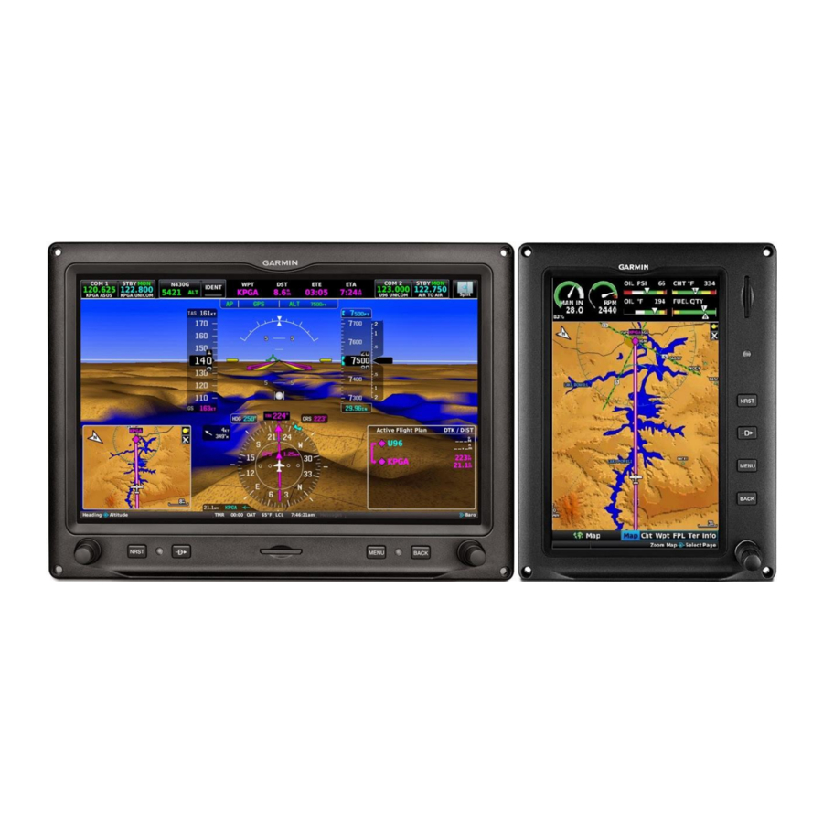
The G3X Touch is scalable with a variety of configurations made up of the 7” portrait GDU 470 and the 10” landscape GDU 460. Installations may consist of one or both display types in any combination from one to three displays (or up to four displays total in tandem cockpit aircraft). - Page 8 Single 7” Portrait GDU (PFD with MFD in split mode, No EIS) Single 10” GDU (PFD & MFD, EIS Optional) FAA Approved AFMS or Supplemental AFM for the Garmin G3X Touch EFIS 190-01754-01 Rev. 4 P a g e | 1-2...
- Page 9 Dual 7” Portrait GDUs (PFD & MFD, EIS Optional) One 10” + One 7” Portrait GDU (PFD & MFD, EIS Optional) 190-01754-01 Rev. 4 FAA Approved AFMS or Supplemental AFM for the Garmin G3X Touch EFIS P a g e | 1-3...
- Page 10 If the installation includes a separate PFD and MFD, reversionary backup is available should a failure of either display occur. In reversionary mode, the remaining G3X Touch display combines critical flight instrumentation with engine readouts (if installed) and navigation information in a single-screen consolidated presentation.
-
Page 11: G3X Touch Gnss (Gps/Sbas) Navigation Equipment Approvals
G3X TOUCH GNSS (GPS/SBAS) NAVIGATION EQUIPMENT APPROVALS To support IFR navigation the G3X Touch must be interfaced to a compatible Garmin GPS or VHF navigator including the following: • GNC 300XL / GPS 155XL * • GNS 4XX(W) / GNS 5XX(W) / GNS 480 * •... - Page 12 This page intentionally left blank. FAA Approved AFMS or Supplemental AFM for the Garmin G3X Touch EFIS 190-01754-01 Rev. 4 P a g e | 1-6...
-
Page 13: Abbreviations And Terminology
Engine Indication System Electronic Stability and Protection Go Around Glide Path GPSS GPS Steering Federal Aviation Administration Final Approach Fix 190-01754-01 Rev. 4 FAA Approved AFMS or Supplemental AFM for the Garmin G3X Touch EFIS P a g e | 1-7... - Page 14 Lateral Navigation with Vertical Guidance Localizer Precision Localizer Precision with Vertical Guidance Localizer Loss of Integrity Maximum Minimum Descent Altitude FAA Approved AFMS or Supplemental AFM for the Garmin G3X Touch EFIS 190-01754-01 Rev. 4 P a g e | 1-8...
- Page 15 Visual Meteorological Conditions VNAV Vertical Navigation VHF Omni-directional Range Vertical Speed Indicator WAAS Wide Area Augmentation System Cross Track Error 190-01754-01 Rev. 4 FAA Approved AFMS or Supplemental AFM for the Garmin G3X Touch EFIS P a g e | 1-9...
- Page 16 Yaw Damper FAA Approved AFMS or Supplemental AFM for the Garmin G3X Touch EFIS 190-01754-01 Rev. 4 P a g e | 1-10...
- Page 17 This page intentionally left blank. 190-01754-01 Rev. 4 FAA Approved AFMS or Supplemental AFM for the Garmin G3X Touch EFIS P a g e | 1-11...
-
Page 19: Limitations
2 LIMITATIONS System Software Requirements The G3X Touch must utilize the following or later FAA approved software versions for this AFMS revision to be applicable: Component Software Version G3X Touch Electronic Flight Instrument NOTE This section is not intended to be a comprehensive list of approved software. It is intended to provide a means to determine if this AFMS revision is applicable to the software that is installed in the aircraft. -
Page 20: Ahrs Operational Area
Moving map displays (ownship position relative to map features) must not be used as the primary or sole means of navigation or course guidance. 2.13 Terrain Display FAA Approved AFMS or Supplemental AFM for the Garmin G3X Touch EFIS 190-01754-01 Rev. 4 P a g e... -
Page 21: Terrain Alerts
The % power display is for information purposes only. 2.19 Weight and Balance Weight and balance data provided by the G3X Touch is for flight planning purposes only. Consult the aircraft’s Pilot’s Operating Handbook for the official weight and balance data. -
Page 22: Glove Usage
Airmen (NOTAM) information. Not all TFRs and NOTAMS may be depicted. 2.21 Glove Usage No device or apparel may cover the pilot’s fingers used to operate the G3X Touch display. 2.22 Service Required It is prohibited to initiate flight when a “Service Required” advisory is present on the PFD, MFD, or EIS display. -
Page 23: Placards
This installation is not limited to VFR. □ This installation is limited to VFR and the following placard is required: AIRCRAFT LIMITED TO VFR 190-01754-01 Rev. 4 FAA Approved AFMS or Supplemental AFM for the Garmin G3X Touch EFIS P a g e | 2-5... - Page 24 This page intentionally left blank. FAA Approved AFMS or Supplemental AFM for the Garmin G3X Touch EFIS 190-01754-01 Rev. 4 P a g e | 2-6...
-
Page 25: Emergency Procedures
ADC fails, the G3X Touch will automatically revert and use air data from the G5. An amber ADC REVERT annunciation will automatically be displayed on the PFD and air data from the G5 will be displayed on the G3X Touch. If installed, the GFC 500 autopilot will function normally. -
Page 26: Attitude Aligning / Keep Wings Level
(to cancel disconnect tone and extinguish annunciator) G3X Touch Altimeter Barometric Window Cyan If a G5 Standby Flight Instrument is installed and the G3X Touch Altimeter Barometric Setting window is cyan and the digits are changing without the pilot manually adjusting the Barometric Altimeter setting knob on the G5, disable the G5 / G3X Touch Baro synchronization as follows: 1. -
Page 27: Erroneous Air Data Or Attitude Information (G5 Standby Flight Instrument Installed)
ADC REVERT, AHRS REVERT, and ECS FAIL messages will be displayed. This will restore the autopilot and flight director. G3X Touch Failure Annunciations If a G3X Touch function fails, a large red ‘X’ is typically displayed over the instrument(s) or data experiencing the failure. Upon G3X Touch power-up, certain instruments remain invalid as equipment begins to initialize. -
Page 28: Heading Failure, Loss Of Magnetometer Data, Or Magnetic Field Error
X, and a Amber “HDG” on the display 1. Use standby magnetic compass. NOTE: If the G3X Touch DG/HSI has a valid GPS signal the G3X Touch DG/HSI instrument will display the GPS track information in magenta. 3.11 PFD Failure PFD failure is indicated by the loss of displayed information on the PFD, including a blank, frozen, or unresponsive display. -
Page 29: Terrain Alerts
NOTE: The arrow “CAUTION, Sink indicates the Rate” obstacle is outside the Synthetic Vision field of view. 190-01754-01 Rev. 4 FAA Approved AFMS or Supplemental AFM for the Garmin G3X Touch EFIS P a g e | 3-5... -
Page 30: Warnings, Cautions, And Advisories
Display is in split screen mode and Select full screen mode on display to view WARNING WARNING annunciations are not annunciations. displayed. FAA Approved AFMS or Supplemental AFM for the Garmin G3X Touch EFIS 190-01754-01 Rev. 4 P a g e | 3-6... - Page 31 AIR MISCOMP other sources to identify erroneous Touch airspeed or altitude and the G5 IAS MISCOMP information. airspeed or altitude. 190-01754-01 Rev. 4 FAA Approved AFMS or Supplemental AFM for the Garmin G3X Touch EFIS P a g e | 3-7...
- Page 32 The unit will not be able to perform the NO COMP the PFD to determine which unit is in error. miscompare monitor function. FAA Approved AFMS or Supplemental AFM for the Garmin G3X Touch EFIS 190-01754-01 Rev. 4 P a g e | 3-8...
-
Page 33: Normal Procedures
5. Select Internal for VFR only flight 6. Press and Hold BACK Button to return to normal PFD display G3X Touch CDI source --------------- Touch the HSI display on the PFD. PFD Options window opens. In the CDI Source window ------------------... -
Page 34: Com Radio Tuning (Optional)
Changing the Navigation Source When an external navigator that supports both GPS and VOR/ILS capabilities (i.e., GTN or GNS Series) is selected, the external navigator’s CDI Key is used to switch the G3X Touch HSI between GPS and VOR/ILS navigation. -
Page 35: Approaches
1. Navigation Source ------------------------------------------ Select GPS on the external navigator 2. Select waypoint and execute the Direct-TO on the external navigator 3. G3X Touch CDI source --------------------------------------- Touch the HSI display on the PFD. PFD Options window opens. 4. Select the external navigator from the CDI Source window (GPS). - Page 36 Touch the Highlight Minimums window. • Enter Barometric Altitude Minimums and touch ENTER 4. G3X Touch CDI source ------------------------------------------------ Touch the HSI display on the PFD. PFD Options window opens. 5. Select the external navigator from the CDI Source window (LOC 1 or 2).
- Page 37 Touch the Highlight Minimums window. • Enter Barometric Altitude Minimums and touch ENTER 4. G3X Touch CDI source ------------------------------------------------ Touch the HSI display on the PFD. PFD Options window opens. 5. Select the external navigator from the CDI Source window (LOC 1 or 2).
- Page 38 7. Navigation Source ---------------------------------------------------- Select GPS on the external navigator 8. Select IAF waypoint and execute the Direct-TO on the external navigator 9. G3X Touch CDI source -------------------------------------------------- Touch the HSI display on the PFD. PFD Options window opens. 10. Select the external navigator from the CDI Source window (GPS 1 or 2).
- Page 39 Touch the Highlight Minimums window. • Enter Barometric Altitude Minimums and touch ENTER 4. G3X Touch CDI source ------------------------------------------------ Touch the HSI display on the PFD. PFD Options window opens. 5. Select the external navigator from the CDI Source window (GPS 1 or 2).
- Page 40 7. Navigation Source ---------------------------------------------------- Select GPS on the external navigator 8. Select IAF waypoint and execute the Direct-TO on the external navigator 9. G3X Touch CDI source -------------------------------------------------- Touch the HSI display on the PFD. PFD Options window opens. 10. Select the external navigator from the CDI Source window (GPS 1 or 2).
- Page 41 Touch the Highlight Minimums window. • Enter Barometric Altitude Minimums and touch ENTER 4. G3X Touch CDI source ------------------------------------------------ Touch the HSI display on the PFD. PFD Options window opens. 5. Select the external navigator from the CDI Source window (GPS 1 or 2).
- Page 42 Touch the Highlight Minimums window. • Enter Barometric Altitude Minimums and touch ENTER 4. G3X Touch CDI source ------------------------------------------------ Touch the HSI display on the PFD. PFD Options window opens. 5. Select the external navigator from the CDI Source window (GPS 1 or 2).
- Page 43 7. Navigation Source ---------------------------------------------------- Select GPS on the external navigator 8. Select IAF waypoint and execute the Direct-TO on the external navigator 9. G3X Touch CDI source -------------------------------------------------- Touch the HSI display on the PFD. PFD Options window opens. 10. Select the external navigator from the CDI Source window (GPS 1 or 2).
- Page 44 Touch the Highlight Minimums window. • Enter Barometric Altitude Minimums and touch ENTER 4. G3X Touch CDI source ------------------------------------------------ Touch the HSI display on the PFD. PFD Options window opens. 5. Select the external navigator from the CDI Source window (GPS 1 or 2).
- Page 45 7. Navigation Source ---------------------------------------------------- Select GPS on the external navigator 8. Select IAF waypoint and execute the Direct-TO on the external navigator 9. G3X Touch CDI source -------------------------------------------------- Touch the HSI display on the PFD. PFD Options window opens. 10. Select the external navigator from the CDI Source window (GPS 1 or 2).
-
Page 46: Barometric Minimums Alert
8. Set Missed Approach Altitude ------------------------------------ Touch the Reference Altitude display. Enter the Missed Approach Altitude. Barometric Minimums Alert A barometric minimums alert is provided in the G3X Touch to enhance the pilot’s awareness of approaching altitude minimums while flying an instrument approach procedure. Setting the barometric minimums alert bug: 1. -
Page 47: Disable Electronic Stability Protection (Esp)
5. Press and Hold the BACK button to close the Automatic Flight Control System window and return to PFD display. 190-01754-01 Rev. 4 FAA Approved AFMS or Supplemental AFM for the Garmin G3X Touch EFIS P a g e | 4-15... - Page 48 This page intentionally left blank. FAA Approved AFMS or Supplemental AFM for the Garmin G3X Touch EFIS 190-01754-01 Rev. 4 P a g e | 4-16...
-
Page 49: Performance
5 PERFORMANCE No change. 190-01754-01 Rev. 4 FAA Approved AFMS or Supplemental AFM for the Garmin G3X Touch EFIS P a g e | 5-1... - Page 50 This page intentionally left blank. FAA Approved AFMS or Supplemental AFM for the Garmin G3X Touch EFIS 190-01754-01 Rev. 4 P a g e | 5-2...
-
Page 51: Weight And Balance
6 WEIGHT AND BALANCE See current weight and balance data. 190-01754-01 Rev. 4 FAA Approved AFMS or Supplemental AFM for the Garmin G3X Touch EFIS Page | 6-1... - Page 52 This page intentionally left blank. FAA Approved AFMS or Supplemental AFM for the Garmin G3X Touch EFIS 190-01754-01 Rev. 4 Page | 6-2...
-
Page 53: System Description
7 SYSTEM DESCRIPTION The G3X Touch System increases situational awareness by replacing the traditional instruments on the panel with an easy-to-scan Primary Flight Display (PFD) that features a horizon, airspeed, attitude, altitude, vertical speed, heading, and course deviation information. Primary Flight Instruments Attitude information is displayed over a virtual blue sky and synthetic ground with a white horizon line. - Page 54 The end of the trend vector gives the heading predicted in 6 seconds, based on the present turn rate. A standard-rate turn is shown on the indicator by the trend vector stopping at the standard FAA Approved AFMS or Supplemental AFM for the Garmin G3X Touch EFIS 190-01754-01 Rev. 4...
-
Page 55: Vertical Deviation Indicators
Indicator. The green 'G' indicates an external glideslope source. If a localizer frequency is tuned and there is no glideslope signal, “NO GS” is annunciated. 190-01754-01 Rev. 4 FAA Approved AFMS or Supplemental AFM for the Garmin G3X Touch EFIS P a g e | 7-3... -
Page 56: Hsi Annunciations
The magenta 'V' indicates a VNAV profile is active. HSI Annunciations Some or all HSI annunciations may appear in the four quadrants of the G3X Touch HSI depending on the external navigator(s) configured. Amber LOI – Loss of GPS integrity Amber or Magenta VFR –... -
Page 57: Display Of Pfd Information On Mfd
Display of PFD information on MFD MFDs installed as part of the G3X touch system can display PFD information if manually selected by the pilot, or will automatically do so if the installed PFD display fails. The display of PFD information on an MFD is a duplication of the original PFD information and is not an independent compilation of data from other sources. -
Page 58: Minimum Altitude Display And Alerting
The G3X Touch is capable of interfacing with several remote transponders providing Mode S interrogation and reply capabilities. Transponder tuning for panel mount transponders is also supported. Ground Mode Ground Mode is normally selected automatically when the aircraft is on the ground. The transponder powers up in the mode it was in when shut down. -
Page 59: Aoa Probe (Optional)
7.10 AOA Probe (Optional) The G3X Touch PFD will display angle of attack from the GAP 26 AOA probe if installed. The GSU 25D uses the pressure from the GAP 26 probe and the pitot/static pressures it already receives from the existing aircraft pitot/static system to determine the aircraft’s angle of attack (AOA).
Need help?
Do you have a question about the G3X Touch and is the answer not in the manual?
Questions and answers