Garmin G3X Pilot's Manual
Pilots guide
Hide thumbs
Also See for G3X:
- User manual ,
- Installation manual (1011 pages) ,
- Pilot's manual (470 pages)
Table of Contents
Advertisement
Quick Links
Advertisement
Table of Contents

Related Manuals for Garmin G3X


Summary of Contents for Garmin G3X
- Page 1 ™ Pilot’s Guide...
- Page 3 SYSTEM OVERVIEW FLIGHT INSTRUMENTS CNS INTERFACE GPS NAVIGATION FLIGHT PLANNING HAZARD AVOIDANCE ADDITIONAL FEATURES INTEGRATED AUTOPILOT ANNUNCIATIONS & ALERTS APPENDIX INDEX...
- Page 5 Garmin Ltd. or its ® ® ® ® subsidiaries. G3X is a trademark of Garmin Ltd. or its subsidiaries. These trademarks may not be ™ used without the express permission of Garmin. Jeppesen is a registered trademark of Jeppesen, Inc. ®...
- Page 6 WARNING: Navigation and terrain separation must NOT be predicated upon the use of the terrain function. The G3X Terrain Proximity feature is NOT intended to be used as a primary reference for terrain avoidance and does not relieve the pilot from the responsibility of being aware of surroundings during flight.
- Page 7 Although unlikely, it may be possible for erroneous operation to occur without a fault indication shown by the G3X. It is thus the responsibility of the pilot to detect such an occurrence by means of cross- checking with all redundant or correlated information available in the cockpit.
- Page 8 FAA/FCC regulations. NOTE: All visual depictions contained within this document, including screen images of the G3X panel and displays, are subject to change and may not reflect the most current G3X system and aviation databases. Depictions of equipment may differ slightly from the actual equipment.
- Page 9 Added ability to use VNAV when using an external GPS navigation Source • Added Softkey to Terrain Page to quickly enabled/disable terrain alerts • Added display of Navaid frequency to PFD bearing pointer data fields RR-1 190-01115-00 Rev. F Garmin G3X Pilot’s Guide...
- Page 10 System Software Version 6.00 - 6.10 : • Added baro minimums altitude reference bug and audio alert to PFD 2011 • Changed CRS Softkey on PFD Page to indicate which course it controls (LOC, VOR, or OBS). RR-2 Garmin G3X Pilot’s Guide 190-01115-00 Rev. F...
- Page 11 Lean Mode is active • Changed AP NAV Softkey on PFD Page to cancel armed GS Mode on the first press if GPS Mode is active and LOC and GS Modes are both armed RR-3 190-01115-00 Rev. F Garmin G3X Pilot’s Guide...
- Page 12 Blank Page RR-4 Garmin G3X Pilot’s Guide 190-01115-00 Rev. F...
-
Page 13: Table Of Contents
Table of Contents Section 1 System Overview ................1 1.1 Line Replaceable Units .....................1 G3X Standard Panel ......................4 G3X Upgraded Panel ......................5 Split-Screen vs. Full-Screen Configurations ................6 External Navigators (Optional) ....................6 Integrated Autopilot (Optional) ..................... 7 1.2 Display Overview ......................8... - Page 14 Map Range ........................121 Map Panning ........................122 Fuel Range Ring ....................... 124 Measuring Bearing and Distance ..................125 Topography ........................126 Satellite View ........................127 Map Page Traffic ....................... 128 Map Symbols ........................128 Garmin G3X Pilot’s Guide 190-01115-00 Rev. F...
- Page 15 Activating Services ......................176 XM Satellite Weather Products ..................176 Using XM Satellite Weather Products ................187 7.2 Terrain ........................191 Synthetic Vision ........................ 192 Terrain Information ......................192 Terrain Views ........................193 Terrain Settings ........................ 194 190-01115-00 Rev. F Garmin G3X Pilot’s Guide...
- Page 16 8.8 Flight Data Logging ....................236 Section 9 Integrated Autopilot (Optional) ..........237 9.1 Integrated Autopilot Operation ................238 Controls ........................... 238 G3X Autopilot Status Box ....................241 Integrated Autopilot Modes ....................243 9.2 Vertical Modes .......................244 Pitch Hold Mode (PIT)....................... 245 Selected Altitude Capture mode (ALTS) ................
- Page 17 Appendix C: SD Card Use and Databases ..............309 Installing and Removing SD Cards ..................309 G3X Databases ........................ 310 Updating G3X Databases ....................313 Exporting Track Logs and User Waypoints ................315 Importing/Exporting Flight Plans ..................316 Flight Data Logging ......................316 Appendix D: Map Datum and Location Formats ............317...
- Page 18 Appendix F: Abnormal Operation ................323 Loss of GPS Position ......................323 Hazard Display with Loss of GPS Position ................323 G3X System Failure Annunciations ..................324 Unusual Attitudes ......................325 Reversionary Mode (Full-Screen) ..................325 Failure of the External GPS Navigation Source ..............326 Synthetic Vision Troubleshooting ..................
-
Page 19: Section 1 System Overview
System Overview SECTION 1 SYSTEM OVERVIEW The G3X System presents flight instrumentation, position, navigation, communication, and identification information to the pilot using 7” Wide VGA (800x480) flat-panel color display(s). 1.1 LINE REPLACEABLE UNITS The system is distributed across the following Line Replaceable Units (LRUs): •... -
Page 20: System Overview
System Overview • GSU 73 Garmin Sensor Unit sub-system for the G3X (Air Data Computer (ADC), Engine/ – Airframe Unit, and the Attitude and Heading Reference System (AHRS)) – ADC: Processes data from the pitot-static system and outside air tem- perature (OAT) sensor. - Page 21 This unit receives power directly from the AHRS and communicates with it via an RS-485 digital interface. GMU 44 • GTP 59 Temperature Probe: Provides raw air temperature data. – GTP 59 190-01115-00 Rev. F Garmin G3X Pilot’s Guide...
-
Page 22: G3X Standard Panel
GSU 73 Garmin Sensor Unit Air Data Computer Airspeed Altitude Vertical Speed GTP 59 Temperature Engine/Airframe Probe Unit GMU 44 AHRS Magnetometer Attitude Heading Heading Rate of Turn Slip/Skid G3X Standard Panel (Split-Screen) Garmin G3X Pilot’s Guide 190-01115-00 Rev. F... -
Page 23: G3X Upgraded Panel
A typical upgraded panel would have the left GDU configured as a full-screen PFD and the right GDU configured as a full-screen MFD. The following is an example of a upgraded G3X panel using a GDU 370 and a GDU 375; however, two GDU 370s can be used if XM is not needed. -
Page 24: Split-Screen Vs. Full-Screen Configurations
When using an external GPS navigator with the G3X, press the INTERNAL Softkey on the Active Flight Plan Page or Direct-To Page to make changes to the active flight plan from the G3X. Press the EXTERNAL Softkey to return to the external GPS navigator’s flight plan. -
Page 25: Integrated Autopilot (Optional)
Non-WAAS external navigators do not support MapMX. Refer to the G3X Installation Manual for more information. EXTERNAL GPS NAVIGATOR FAILURE In the event that all configured external GPS navigators fail, the G3X reverts to its internal VFR GPS for navigation and flight plan modification. INTEGRATED AUTOPILOT (OPTIONAL) The G3X can also communicate with various third-party external autopilot units. -
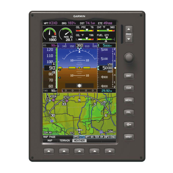
Page 26: Display Overview
System Overview 1.2 DISPLAY OVERVIEW 7” WVGA (800x480) SD Card Slot Color Display Range (RNG) Key FMS Joystick Display Bezel Hardkeys Softkeys Display Overview (Split-Screen) Garmin G3X Pilot’s Guide 190-01115-00 Rev. F... -
Page 27: Secure Digital (Sd) Cards
NOTE: Refer to Appendix C for more information on SD Card use and databases. The G3X data card slot uses Secure Digital (SD) cards and is located on the upper right side of the display bezel(s). The SD card can be used for software updates, checklist files, flight data logging, exporting Track Logs/User Waypoints, and Importing/ Exporting Flight Plans. -
Page 28: G3X Controls
With the appropriate autopilot mode selected, move the FMS Joystick (up/down) to adjust the mode reference for Vertical Speed, Altitude Hold, and Pitch Hold modes, or move the FMS Joystick (left/right) to decrease the mode reference for Roll Hold mode. Garmin G3X Pilot’s Guide 190-01115-00 Rev. F... - Page 29 Press to display the Nearest Page for viewing the nearest airports, intersections, NDBs, VORs, waypoints, frequencies, and airspaces Softkey Press to select softkey shown above the bezel key on the display Selection Keys 190-01115-00 Rev. F Garmin G3X Pilot’s Guide...
-
Page 30: System Power-Up
Current database information is displayed during power-up including valid operating dates, cycle number, and database type. When this information has been reviewed for currency (to ensure that no databases have expired), the pilot is prompted to continue. Database Information Garmin G3X Pilot’s Guide 190-01115-00 Rev. F... -
Page 31: System Operation
Datalink Weather Advisory Pressing the ENT Key acknowledges this information. 1.6 SYSTEM OPERATION NOTE: The G3X display operation can be configured from the DSPL Page in Config Mode (refer to the G3X Installation Manual for more information). DISPLAY OPERATION NOTE: In a reversionary situation where failure occurs with all the GDUs... - Page 32 PFD can be accessed by navigating to the PFD Page (see Section 1.7, Access- ing System Functionality). – The MFD occupies the bottom portion of the display. G3X Split-Screen Only (Normal Mode) • Full-Screen PFD/MFD Configuration (Normal Mode) – In normal mode the displays can be configured to have a dedicated PFD and MFD or have an optional split-screen PFD.
- Page 33 G3X Normal Mode (Optional Split-Screen PFD) • Full-Screen PFD/MFD Configuration (Reversionary Mode) In the event of a display failure, the G3X System automatically switches to reversionary (backup) mode. In reversionary mode, all flight information is presented on the remaining display in the split-screen configuration.
-
Page 34: Pfd Display Configuration
PFD page and full-screen MFD pages without split-screen) PFD1 PFD2 G3X Multi-display Normal Mode (example) • Multi-Display (Reversionary Mode) If the system detects a failure in PFD1, the MFD enters reversionary mode. If the MFD fails, PFD1 and PFD2 enter reversionary mode. A failure of PFD2 is not considered an emergency and will not cause either of the remaining displays to enter reversionary mode. -
Page 35: G3X System Annunciations
All instruments should be operational within one minute of power- up. If any instrument remains flagged, and it is not likely an installation related problem, the G3X should be serviced by a Garmin-authorized repair facility . PFD Initialization 190-01115-00 Rev. -
Page 36: Ahrs Operation
AHRS OPERATION The Attitude and Heading Reference System (AHRS) performs attitude, heading, and vertical acceleration calculations for the G3X System, utilizing GPS, magnetometer, and air data in addition to information from its internal sensors. Attitude and heading information are updated on the PFD while the AHRS receives appropriate combinations of information from the external sensor inputs. -
Page 37: Accessing System Functionality
NOTE: Flight Log and Track Log must be accessed from the MFD in a Multiple Display system. The G3X has a dedicated MENU Key. Press once to display a context-sensitive list of options for the page or the dedicated PFD. Press twice to display the Main Menu. - Page 38 4) Press the FMS Joystick, CLR Key, EXIT Softkey, or press the MENU Key to remove the menu and cancel the operation. Main Menu (Split-Screen) Main Menu (Split-Screen PFD) Main Menu (Full-Screen MFD) Garmin G3X Pilot’s Guide 190-01115-00 Rev. F...
-
Page 39: Data Entry
The FMS Joystick can be used for directly entering alphanumeric data into the G3X. In some instances, such as when entering an identifier, the G3X tries to predict the desired identifier based on the characters being entered. In this case, if the desired identifier appears, use the ENT Key to confirm the entry without entering the rest of the identifier manually. - Page 40 Navigation Bar is highlighted blue, the user can cycle through the pages using the FMS Joystick. If the Page Navigation Bar is not highlighted blue, the user can interact with the current page (if available). Garmin G3X Pilot’s Guide 190-01115-00 Rev. F...
-
Page 41: Main Pages
1) If necessary, press the FMS Joystick to begin interaction with the Page Navigation Bar. 2) Turn the FMS Joystick until the desired page is selected (PFD (split-screen only), MAP, WPT, WX, TER, TRF (optional) XM, INFO, ENG). 190-01115-00 Rev. F Garmin G3X Pilot’s Guide... - Page 42 PFD Page (PFD) (split-screen) Traffic Page (TRF) Map Page (MAP) XM Audio Page (XM) (optional) Waypoint Page (WPT) Info Page (INFO) Weather Page (WX) (optional) Engine Page (ENG) Terrain Page (TER) Main Pages (Split-Screen) Garmin G3X Pilot’s Guide 190-01115-00 Rev. F...
- Page 43 ATIS, AWOS, or ASOS frequency. • VOR (VHF Omnidirectional Radio Beacon)—identifier, facility type (symbol), bearing, distance, and frequency. • NDB (Non Directional Beacons)—identifier, facility, type (symbol), bearing, distance, and frequency. • INT (Intersection)—identifier, bearing, and distance. 190-01115-00 Rev. F Garmin G3X Pilot’s Guide...
- Page 44 Nearest Airport Weather (WX) (GDU 375) Nearest Cities (CTY) Nearest VORs (VOR) Nearest ARTCC (ATC) Nearest NDBs (NDB) Nearest FSS (FSS) Nearest Intersections (INT) Nearest Airspace (ASPC) Visual Reporting Point (VRP) (Atlantic) Nearest Pages (Split-Screen) Garmin G3X Pilot’s Guide 190-01115-00 Rev. F...
-
Page 45: Main Page Softkeys
When a softkey function is disabled, the softkey label is subdued (dimmed). Softkey Softkey Names (Displayed) Bezel Mounted Softkeys (Press) Softkeys (WPT Page) 190-01115-00 Rev. F Garmin G3X Pilot’s Guide... -
Page 46: Pfd Softkeys
BARO BARO MINIMUMS XX GAL BACK MINIMUMS Allows the pilot to set or clear the barometric minimums altitude reminder BARO Allows the pilot to change the barometric setting BACK Returns to top-level softkeys Garmin G3X Pilot’s Guide 190-01115-00 Rev. F... - Page 47 Allows the pilot to adjust the VOR course LOC CRS Allows the pilot to adjust the localizer course CODE Allows the pilot to enter the transponder code and displays the second-level CODE softkeys 190-01115-00 Rev. F Garmin G3X Pilot’s Guide...
- Page 48 SET ID Allows the pilot to set the Flight ID. (The Flight ID must be configured to ‘Set By Pilot’ for the SET ID softkey to be displayed). BACK Returns to previous level softkeys Garmin G3X Pilot’s Guide 190-01115-00 Rev. F...
- Page 49 ALT/PTCH Softkey selected HDG/ROLL Initial press allows the pilot to adjust the heading bug and displays lateral mode softkeys; subsequent press returns to top-level softkeys 190-01115-00 Rev. F Garmin G3X Pilot’s Guide...
-
Page 50: Map Page Softkeys
Displays/removes weather information TRAFFIC Displays/removes traffic information Press the BACK Softkey to return to the top-level softkeys. VFR MAP IFR MAP TOPO SAT VIEW BACK VFR MAP IFR MAP LOW AWY HIGH AWY BACK Garmin G3X Pilot’s Guide 190-01115-00 Rev. F... -
Page 51: Waypoint Page Softkeys
Waypoint (WPT) Page Softkeys (Full-Screen) INFO Displays waypoint information RUNWAY Displays runway information (split-screen only) CHART Displays optional FliteCharts AOPA or DIRECTORY Displays airport directory information WEATHER Displays METAR and TAF text (optional) 190-01115-00 Rev. F Garmin G3X Pilot’s Guide... - Page 52 Terrain (TER) Page Softkeys (Split-Screen) SETTINGS DISABLE Terrain (TER) Page Softkeys (Full-Screen) Displays the Terrain Page Map View PROFILE Displays the Terrain Page Profile View. SETTINGS Displays the Terrain Setup Page DISABLE Toggles terrain alerts on/off. Garmin G3X Pilot’s Guide 190-01115-00 Rev. F...
-
Page 53: Info Page Softkey
VOL + MUTE VOL - Decreases XM audio volume VOL + Increases XM audio volume MUTE Toggles XM audio on/off BACK Returns to top-level softkeys INFO PAGE SOFTKEY MESSAGES MESSAGES Displays system status messages 190-01115-00 Rev. F Garmin G3X Pilot’s Guide... - Page 54 ENG PAGE SOFTKEYS (EXAMPLE CONFIGURATION) NOTE: The Engine (ENG) Page softkeys displayed are dependant on the configuration. Refer to the G3X Installation Manual for information on configuring the Engine Page. If the Engine Page information configured exceeds one page, additional engine gauges may be distributed among the 1st, 2nd, and 3rd softkeys as required.
-
Page 55: Flight Planning Softkeys
Displays the ‘Activate Flight Plan?’ Window Displays the ‘New Flight Plan’ Window IMPORT Displays the available flight plans to import from the SD Card EXPORT Exports the selected flight plan EXIT Exits the Flight Plan Pages 190-01115-00 Rev. F Garmin G3X Pilot’s Guide... -
Page 56: Nearest Page Softkeys
Displays/removes the nearest heliports EXIT Exits the Nearest Pages Various softkeys revert to the previous level after 45 seconds of inactivity (e.g., PAN MAP, VOLUME, etc), other softkeys require manual de-selection (e.g., TERRAIN, WEATHER, PANEL, etc.). Garmin G3X Pilot’s Guide 190-01115-00 Rev. F... -
Page 57: Accessing The Information (Info) Page
Internal system checking is performed to ensure the GPS receiver is providing accurate data to the GDU(s). The G3X GDUs can be configured to share GPS information (refer to the G3X Installation Manual for configuration information). For example, a GDU can be configured to share its GPS position, velocity, and time data with another GDU. - Page 58 INFO Page (Full Screen) Viewing GPS receiver status information: 1) If necessary press the FMS Joystick to begin interaction with the Navigation Bar. 2) Turn the FMS Joystick until the Info Page is selected. Garmin G3X Pilot’s Guide 190-01115-00 Rev. F...
-
Page 59: New Location
45° above the horizon, and the center point shows the position directly overhead. Each satellite is represented by a square containing the Pseudo-Random Noise (PRN) number (i.e., satellite identification number). 190-01115-00 Rev. F Garmin G3X Pilot’s Guide... -
Page 60: Position
2) Turn or move the FMS Joystick to highlight ‘Change Nearest Type’ and press the ENT Key. 3) Move the FMS Joystick to highlight the desired nearest type option (Automatic, Airport, VOR, NDB, Intersection, City, Waypoint), and press the ENT Key. Garmin G3X Pilot’s Guide 190-01115-00 Rev. F... -
Page 61: Data Fields And Layout (Full-Screen Mfd)
3) Move the FMS Joystick to highlight the desired Data Field. 4) Turn the FMS Joystick to access a list of available Data Field options. 5) Turn or move the FMS Joystick to highlight the desired Data Field, and press the ENT Key. 190-01115-00 Rev. F Garmin G3X Pilot’s Guide... -
Page 62: System Settings
The System Setup option in the Main Menu allows management of the following system parameters: • Transponder (optional) • Units • Data Bar Fields • Date & Time • Display • Position • Sound • Alarms System Setup Menu (Split-Screen) Garmin G3X Pilot’s Guide 190-01115-00 Rev. F... -
Page 63: Transponder
4) Move the FMS Joystick to highlight the ‘ADS-B Transmit’ Field. 5) Turn the FMS Joystick to highlight ‘Enabled’ or ‘Disabled’. 6) Press the FMS Joystick, the CLR Key, the EXIT Softkey or the MENU Key to return to the previous page. 190-01115-00 Rev. F Garmin G3X Pilot’s Guide... -
Page 64: Data Bar Fields
2) Turn or move the FMS Joystick to highlight ‘System Setup...’ and press the ENT Key. 3) With ‘Data Bar Fields’ highlighted, press the ENT Key. 4) Move the FMS Joystick to highlight the desired ‘Field’. Garmin G3X Pilot’s Guide 190-01115-00 Rev. F... - Page 65 ‘REV’ is displayed in yellow and ‘GPS’ is displayed in magenta in the upper left corner of the Data Bar when all external GPS navigation sources fail. External GPS Failure. Reverted to Internal GPS External GPS Navigation Failure 190-01115-00 Rev. F Garmin G3X Pilot’s Guide...
-
Page 66: Display
Backlight Intensity based on the aircraft’s instrument lighting bus voltage. With ‘Manual’ selected, the pilot can manually adjust the desired backlight intensity (1-10). After each power cycle the Backlight Intensity is set to the default, which is configurable. Refer to the G3X Installation Manual for more information. ‘EIS Display Location’... -
Page 67: Color Mode
• User Selected—Enables the user to choose between ‘AUTO’ and ‘PFD’ via the Display Setup menu. For more information on how to enable the ‘EIS Display Location’ setting in Configuration Mode refer to the G3X Installation Manual. 190-01115-00 Rev. F Garmin G3X Pilot’s Guide... - Page 68 Saving a screenshot: 1) With screenshots enabled (see above), navigate to the desired screen. 2) Press and hold the FMS Joystick until the screen flashes indicating the screenshot was saved to the SD Card. Garmin G3X Pilot’s Guide 190-01115-00 Rev. F...
-
Page 69: Sound
(e.g., “Approaching Airspace” or “Arriving at Waypoint”). Alert Volume (e.g., terrain, traffic, autopilot, etc.) is set in configuration mode (refer to the G3X Installation Manual for more information). Sound Setup Page (Split-Screen) Adjusting XM and/or Message Volume: 1) Press the MENU Key twice to display the Main Menu. -
Page 70: Units
UNITS Changing unit settings: 1) Press the MENU Key twice to display the Main Menu. 2) Turn or move the FMS Joystick to highlight ‘System Setup...’ and press the ENT Key. Garmin G3X Pilot’s Guide 190-01115-00 Rev. F... -
Page 71: Date & Time
FMS Joystick. 5) Press the FMS Joystick, the CLR Key, the EXIT Softkey or the MENU Key to return to the previous page. Date & Time Setup Page (Split-Screen) 190-01115-00 Rev. F Garmin G3X Pilot’s Guide... -
Page 72: Position
Position Setup Page (Split-Screen) ALARMS The Alarms Page allows the pilot to turn airspace alarms On/Off, set an Altitude Buffer, Arrival Alarm, Next Waypoint Alarm, Proximity Alarm, and Fuel Tank Reminder Alarm. Garmin G3X Pilot’s Guide 190-01115-00 Rev. F... - Page 73 The Fuel Tank Timer (FUEL TIMER) data field option is the elapsed time since the ‘Fuel Tank’ Reminder alarm was last issued (HH:MM). Airspace Alarms (Split-Screen) Alarms (Full-Screen MFD) Nav Alarms (Split-Screen) 190-01115-00 Rev. F Garmin G3X Pilot’s Guide...
-
Page 74: Setting Airport Criteria
5) Move the FMS Joystick to highlight the desired field and turn the FMS Joystick to select the desired option from the menu. Press the ENT Key if necessary to highlight the next field. Garmin G3X Pilot’s Guide 190-01115-00 Rev. F... - Page 75 4) Turn or move the FMS Joystick to select ‘Set Airport Criteria’, and then press the ENT Key. A window appears with the current settings. 5) Press the MENU Key. 6) With ‘Restore Default’ highlighted press the ENT Key. 190-01115-00 Rev. F Garmin G3X Pilot’s Guide...
- Page 76 System Overview Blank Page Garmin G3X Pilot’s Guide 190-01115-00 Rev. F...
-
Page 77: Section 2 Flight Instruments
Press the FMS Joystick if necessary to begin interaction with the Page Navigation Bar. 2) Turn the FMS Joystick to select the PFD Page. The following flight instruments and supplemental flight data are displayed on the PFD and/or PFD Page (split-screen). 190-01115-00 Rev. F Garmin G3X Pilot’s Guide... - Page 78 Flight Instruments Garmin G3X Pilot’s Guide 190-01115-00 Rev. F...
-
Page 79: Airspeed Indicator
Zero Pitch Line Trim Indicator Current Track Indicator (Heading Strip) Flap Indicator Current Heading Navigation Source Selected Heading Bug Bearing 1 Information Window Turn Rate Indicator Outside Air Temperature (OAT) Autopilot Status Box 190-01115-00 Rev. F Garmin G3X Pilot’s Guide... -
Page 80: Airspeed Indicator
Flight Instruments AIRSPEED INDICATOR NOTE: The G3X Vspeed Reference values and Flaps Tick Mark values depend upon the aircraft’s specific system configuration and may vary from the examples discussed in this section. The Airspeed Indicator displays airspeed on a rolling number gauge using a moving tape. - Page 81 V . Using TAS instead of IAS causes V to be reduced at high altitudes. If configured, the G3X can calculate and display this reduction in V . A solid red band is used between the TAS adjusted V...
-
Page 82: Attitude Indicator
Angle of bank is indicated by the position of the pointer on the roll scale. Slip/skid is indicated by the location of the ball. Roll Pointer Roll Scale Horizon Line Aircraft Symbol Slip/Skid Indicator Land Representation Pitch Scale Sky Representation Roll Scale Zero Attitude Indicator Garmin G3X Pilot’s Guide 190-01115-00 Rev. F... -
Page 83: Altimeter
1) From the PFD Page (one display) or PFD (two display), press the ALT (or ALT/PTCH if the Integrated Autopilot is configured) Softkey. 2) Turn the FMS Joystick to set the Selected Altitude in 100-ft increments. 190-01115-00 Rev. F Garmin G3X Pilot’s Guide... -
Page 84: Selecting The Altimeter Barometric Pressure Setting
Altimeter. Once the aircraft reaches the user-defined MDA/ DH, the bug and text turn yellow and the aural alert, “Minimums. Minimums”, is heard. Garmin G3X Pilot’s Guide 190-01115-00 Rev. F... - Page 85 1) Press the MENU Key twice to display the Main Menu. 2) Turn or move the FMS Joystick to highlight ‘System Setup...’ and press the ENT Key. 3) Turn or move the FMS Joystick to highlight ‘Sound’, and press the ENT Key. 190-01115-00 Rev. F Garmin G3X Pilot’s Guide...
- Page 86 3) Turn or move the FMS Joystick to highlight ‘Sound’, and press the ENT Key. 4) Move the FMS Joystick to highlight the Altitude Alert field, and select ‘On/ Off’ by turning the FMS Joystick. Garmin G3X Pilot’s Guide 190-01115-00 Rev. F...
-
Page 87: Vertical Speed Indicator (Vsi)
ILS frequency is tuned in the active NAV field of an external navigator. A green diamond acts as the VDI Indicator, like a glideslope needle on a conventional indicator. If a localizer frequency is tuned and there is no glideslope signal, “NO GS” is annunciated. 190-01115-00 Rev. F Garmin G3X Pilot’s Guide... - Page 88 GPS approach. The glidepath is analogous to the glideslope for GPS approaches supporting WAAS vertical guidance (LNAV+V, L/VNAV, LPV). The Glidepath Indicator appears on the G3X as a magenta diamond. If the approach type downgrades past the final approach fix (FAF), “NO GP” is annunciated.
-
Page 89: Horizontal Situation Indicator (Hsi)
Adjusting the selected heading: 1) From the PFD Page (one display) or PFD (two display), press the HDG (or HDG/ROLL if the Integrated Autopilot is configured) Softkey (if necessary). The Heading Box is highlighted. 190-01115-00 Rev. F Garmin G3X Pilot’s Guide... - Page 90 To/From Indicator Current Track Indicator Aircraft Symbol Course Pointer Lateral Deviation Scales Navigation Source Selected Heading Bug Course Deviation Indicator Course Deviation & To/From (CDI) Indicator Rotating Compass Rose Horizontal Situation Indicator (HSI) Garmin G3X Pilot’s Guide 190-01115-00 Rev. F...
-
Page 91: Bearing Pointers And Information Windows
Flight Instruments HSI ANNUNCIATIONS NOTE: Some or all HSI annunciations may appear in the four quadrants of the G3X HSI depending on the external navigator(s) configured (i.e., SL30 Nav/ Comm Transceiver and/or the GTN or GNS Series Units). VFR CDI Scales: ‘1’... - Page 92 • GPS is the bearing source and an the tuned VOR station active waypoint is not selected Bearing Bearing Pointer 2 Pointer 1 Bearing 1 Information Window Bearing 2 Information Window -Identifier -Identifier -Bearing Source -Distance HSI with Bearing Pointers Garmin G3X Pilot’s Guide 190-01115-00 Rev. F...
- Page 93 Scale The CDI is capable of displaying two sources of navigation: GPS or NAV (VOR, localizer) depending on the external navigator(s) configured (refer to the G3X Installation Manual for more information). Color indicates the current navigation source: magenta (for GPS) or green (for VOR and LOC). The full-scale limits for the CDI are defined by a GPS-derived distance when coupled to GPS.
- Page 94 Use the associated external navigator to toggle between GPS and VOR/LOC source types. Refer to the appropriate external navigator Pilot’s Guide (e.g., SL30 Nav/Comm Transceiver Pilot’s Guide, or the GTN or GNS Series Pilot’s Guides) for more information. Garmin G3X Pilot’s Guide 190-01115-00 Rev. F...
- Page 95 Navigator 2 Navigator 2 Navigator (e.g., if the external navigator is a GNS 430, press the CDI Key on the GNS 430 to toggle between GPS1 and LOC1 or GPS2 and LOC2) CDI Source 190-01115-00 Rev. F Garmin G3X Pilot’s Guide...
- Page 96 Press the INTERNAL Softkey on the Active Flight Plan Page or the Direct-to Page, to temporarily allow flight planning through the G3X using the internal GPS flight plan when an external GPS Navigator is configured. Press the EXTERNAL Softkey to return to the external GPS navigator’s flight plan.
- Page 97 HSI. External GPS Failure. Reverted to Internal GPS REV: External Navigation Source failed. Reverted to internal VFR GPS for navigation. External GPS Navigation Failure 190-01115-00 Rev. F Garmin G3X Pilot’s Guide...
- Page 98 The current CDI scale appears in the upper right corner of the HSI. Current CDI Scale Horizontal Situation Indicator (HSI) The Automatic CDI Scale Selection will resume once the default determining factor for the current phase of flight matches the user-selected CDI scale. Garmin G3X Pilot’s Guide 190-01115-00 Rev. F...
- Page 99 Flight Instruments lewing The G3X will automatically slew the LOC course pointer to the correct final approach course when an ILS, LOC, BC, LDA, or SDF approach is active in the external navigator and the appropriate CDI and navigation source are selected on the G3X.
-
Page 100: Trim And Flap Position Indicators (Optional)
TRIM AND FLAP POSITION INDICATORS (OPTIONAL) Elevator Trim, Aileron Trim, Rudder Trim, and Flap Position indicators can be configured from the Engine/Airframe Input Configuration Page in Configuration Mode. Refer to the G3X Installation Manual for more information. Elevator Trim Indicator... -
Page 101: Obs Mode
When OBS Mode is disabled, the GPS flight plan returns to normal operation with automatic sequencing of waypoints, following the course set in OBS Mode. The flight path on the moving map retains the modified course line. 190-01115-00 Rev. F Garmin G3X Pilot’s Guide... - Page 102 1) Press the OBS Key on the external navigator. The ‘Set OBS and Hold’ Active Flight Plan Page menu option is now available. 2) Turn the FMS Joystick on the G3X to select the desired course to/from the waypoint. Syncing to the current aircraft location (without external GPS...
-
Page 103: Supplemental Flight Data
HSI. When the window is selected for display, but wind information is invalid or unavailable, the window displays “No Wind Data”. Showing/hiding wind data: 1) From the full-screen PFD and/or split-screen PFD Page, press the MENU Key. 190-01115-00 Rev. F Garmin G3X Pilot’s Guide... -
Page 104: Vertical Navigation (Vnav)
Speed Indicator (RVSI)) on the Vertical Speed Indicator indicates the required vertical speed to reach the target altitude. The Vertical Navigation feature is only available when navigating a Direct-to or flight plan, and the ground speed is greater than 35 knots. Garmin G3X Pilot’s Guide 190-01115-00 Rev. F... -
Page 105: Using The Vnav Feature
The magenta VNAV Indicator appears on the PFD. A message appears when approaching the VNAV Profile. When the VNAV Indicator is in the vertical center of the Vertical Deviation Scale, the aircraft is at the proper altitude for the VNAV Profile. 190-01115-00 Rev. F Garmin G3X Pilot’s Guide... - Page 106 4) Enter the desired profile into the fields, and press the EXIT Softkey. Vertical Navigation Page (Split-Screen) Waypoint—Enter any waypoint along the currently active route as the • reference waypoint. The reference waypoint defines the target location. Profile—Enter the descent rate. • Garmin G3X Pilot’s Guide 190-01115-00 Rev. F...
- Page 107 2) Turn the FMS Joystick to highlight the Vertical Navigation Page. 3) Press the MENU Key. 4) Turn or move the FMS Joystick to highlight ‘Cancel VNAV Capture’ and press the ENT Key. 190-01115-00 Rev. F Garmin G3X Pilot’s Guide...
- Page 108 Flight Instruments 1) Enter a valid VNAV profile and begin navigation. 2) From the VNAV Page, press (deselect) the CAPTURE Softkey. Garmin G3X Pilot’s Guide 190-01115-00 Rev. F...
-
Page 109: Section 3 Engine Indication System
SECTION 3 ENGINE INDICATION SYSTEM 3.1 EIS DISPLAY & ENG PAGE NOTE: The display of the G3X Engine Indication System depends upon the current configuration and may vary from the examples discussed in this section. The G3X Engine Indication System (EIS) displays critical engine, electrical, and other system parameters on the top portion of the display (split-screen and/or full-screen MFD). - Page 110 If the Engine Page information configured exceeds one page, additional engine gauges may be distributed among the 1st, 2nd, and 3rd softkeys as required. Example Engine (ENG) Page Configuration - TEMPS Softkey Selected (Split-Screen) Example Engine (ENG) Page Configuration- AUX Softkey Selected (Split-Screen) Garmin G3X Pilot’s Guide 190-01115-00 Rev. F...
- Page 111 Displays fuel pressure 13 18 Voltmeter Displays the main bus voltage 14 29 Ammeter Displays the battery load in amperes 15 30 Total Hours (HOURS) Refer to G3X Installation Manual for 16 31 more information. 190-01115-00 Rev. F Garmin G3X Pilot’s Guide...
- Page 112 If sensory data to an instrument becomes invalid or unavailable, a red “X” is displayed across the instrument. Garmin G3X Pilot’s Guide 190-01115-00 Rev. F...
-
Page 113: Eng Page Softkeys (Example Configuration)
ENG PAGE SOFTKEYS (EXAMPLE CONFIGURATION) NOTE: The Engine (ENG) Page softkeys displayed are dependant on the configuration. Refer to the G3X Installation Manual for information on configuring the Engine Page. If the Engine Page information configured exceeds one page, additional engine gauges may be distributed among the 1st, 2nd, and 3rd softkeys as required. - Page 114 EGT for that cylinder. Cylinder Peak Temperature Indicates Difference Between Present and Peak Temperature Cylinder to Peak Leaning to First Peak (ENG Page - Full-Screen MFD) Garmin G3X Pilot’s Guide 190-01115-00 Rev. F...
- Page 115 DTIT) is displayed in place of the normal temperature number in light blue text. Difference Between Present and Peak Tem- perature Cylinder Peak Temperature Cylinder with the Tem- perature Closest to Its Peak Value Engine Instrument Display (Split-Screen) 190-01115-00 Rev. F Garmin G3X Pilot’s Guide...
-
Page 116: Fuel Calculator (Optional)
Lean Assist Mode - Turbine Inlet Temperature (ENG Page) 3.3 FUEL CALCULATOR (OPTIONAL) WARNING: The G3X Fuel Calculator and/or Fuel Range Rings are NOT intended to be relied upon as the primary fuel indicator(s), and does not relieve the pilot from the responsibility of proper flight planning. - Page 117 1) From the ENG Page, press the FUEL Softkey. 2) Press Softkey #2 (XX GAL); this resets only Fuel Remaining to the maximum fuel capacity for the aircraft. XX is the airframe specific full fuel quantity. 190-01115-00 Rev. F Garmin G3X Pilot’s Guide...
-
Page 118: Fuel Calculator Softkeys
(optional) FUEL Returns to top-level softkeys CONFIRMING FUEL QUANTITY When the system detects that fuel has been added, a ‘Confirm Fuel Quantity’ Reminder Page appears when the system is powered on. Garmin G3X Pilot’s Guide 190-01115-00 Rev. F... -
Page 119: Confirm Fuel Quantity Softkeys
Adjusting the Fuel Remaining or Fuel Used quantity: 1) Move the FMS Joystick to the Fuel Remaining or Fuel Used Field (if necessary). 2) Turn the FMS Joystick to adjust the desired quantity. 190-01115-00 Rev. F Garmin G3X Pilot’s Guide... -
Page 120: Cas Messages (Optional)
3.4 CAS MESSAGES (OPTIONAL) The CAS messages displayed depend upon the current configuration, and will vary from the examples listed below. Refer to the G3X Installation Manual for more information on configuring CAS messages (if applicable). CAS Messages are grouped by criticality (warning, caution, advisory). The color of the message is based on its urgency and on required action: •... - Page 121 Page is not displayed, or FPL/NRST Pages are displayed on the full-screen PFD). In that case a Check Alerts Triangle is displayed to the right of the Airspeed Indicator as a reminder to check the CAS Messages. CAS Warning Example (Check Alerts Triangle) 190-01115-00 Rev. F Garmin G3X Pilot’s Guide...
- Page 122 If less than four CAS Messages are configured for the system, the CAS Messages are displayed to the right of the Airspeed Indicator and the Check Alerts Triangle is not displayed. CAS Warning Example Garmin G3X Pilot’s Guide 190-01115-00 Rev. F...
-
Page 123: Section 4 Cns Interface
CNS Interface SECTION 4 CNS INTERFACE 4.1 AUTO-TUNING FREQUENCIES (OPTIONAL) NOTE: Refer to the G3X Installation Manual for more information on the G3X optional communication interfaces. Frequencies can be automatically tuned from the following: • Map Page • Nearest Airport Weather Page • Weather Page... - Page 124 4) Press the ENT Key to load the frequency into the standby field of the SL40. If the frequency has an * (additional information available) next to it, press the ENT Key a second time with ‘Tune’ highlighted. Frequency with Additional Information (Split-Screen) Garmin G3X Pilot’s Guide 190-01115-00 Rev. F...
-
Page 125: Remote Transponder Interface (Optional)
ENT Key a second time with ‘Tune’ highlighted. 4.2 REMOTE TRANSPONDER INTERFACE (OPTIONAL) The G3X is capable of interfacing with several remote transponders providing Mode S interrogation and reply capabilities. Selective addressing or Mode Select (Mode S) capability includes the following features: •... - Page 126 Status Transponder Data Box (Split-Screen) With a remote transponder configured, the #2 PFD Softkey becomes XPDR (if a navigation source is not selected) or XPDR/CRS (when the pilot can control the navigation course). Garmin G3X Pilot’s Guide 190-01115-00 Rev. F...
- Page 127 Allows the pilot to enter the transponder code and displays the second-level CODE softkeys Displays second-level MODE softkeys MODE BACK Returns to top-level softkeys CODE Softkey selected IDENT Sends a distinct identity indication to Air Traffic Control (ATC). 190-01115-00 Rev. F Garmin G3X Pilot’s Guide...
-
Page 128: Transponder Mode Selection
2) Press the MODE Softkey. 3) Press the desired mode softkey (STBY / GND, ON, or ALT). Pressing and holding the STBY Softkey activates Ground (GND) Mode and the STBY Softkey becomes the GND Softkey. Garmin G3X Pilot’s Guide 190-01115-00 Rev. F... -
Page 129: Ground Mode
If Altitude Mode is selected, a green ALT indication and transponder code appear in the mode field of the Transponder Data Box, and all transponder replies requesting altitude information are provided with pressure altitude information. 190-01115-00 Rev. F Garmin G3X Pilot’s Guide... -
Page 130: Entering A Transponder Code
CODE Softkey, then the VFR Softkey. When the VFR Softkey is pressed, the pre- programmed VFR code is automatically displayed in the code field of the Transponder Data Box. Pressing the VFR Softkey again restores the previous identification code. Garmin G3X Pilot’s Guide 190-01115-00 Rev. F... -
Page 131: Ident Function
18 seconds. FLIGHT ID REPORTING NOTE: The Flight ID must be configured to ‘Set By Pilot’ in Configuration Mode for the SET ID Softkey to appear. Refer to the G3X Installation Manual for more information. Entering a Flight ID: 1) From the full-screen PFD and/or the split-screen PFD Page, press the XPDR Softkey. - Page 132 CNS Interface Blank Page Garmin G3X Pilot’s Guide 190-01115-00 Rev. F...
-
Page 133: Section 5 Gps Navigation
NOTE: The compass arc is not available in ‘North Up’ map orientation. A compass arc representing the aircraft’s ground track, appears by default on the Map Page. The route line represents the course. Compass Arc Route Line Compass Arc (Map Page) 190-01115-00 Rev. F Garmin G3X Pilot’s Guide... -
Page 134: Using Map Displays
WARNING: The G3X map displays are to be used for situational awareness only. Map displays are used extensively in the G3X to provide situational awareness in flight. Most G3X maps can display the following information: • Airports, NAVAIDs, airspaces, airways, land data (highways, cities, lakes, rivers, borders, etc.) with names... -
Page 135: Map Page Setup
Turn the FMS Joystick to access a list of available options. c) Turn or move the FMS Joystick to highlight ‘North Up’, ‘Track Up’, or ‘DTK Up’, and press the ENT Key. 190-01115-00 Rev. F Garmin G3X Pilot’s Guide... -
Page 136: Gps Navigation
6) Using the FMS Joystick select the desired option and press the ENT Key. 7) Press the FMS Joystick, the CLR Key, or the EXIT Softkey to return to the Map Page with the changed settings. Garmin G3X Pilot’s Guide 190-01115-00 Rev. F... - Page 137 6) Using the FMS Joystick select the desired option and press the ENT Key. 7) Press the FMS Joystick, the CLR Key, or the EXIT Softkey to return to the Map Page with the changed settings. Map Setup Page (City Category) Map Setup Page (Road Category) 190-01115-00 Rev. F Garmin G3X Pilot’s Guide...
- Page 138 7) Press the FMS Joystick, the CLR Key, or the EXIT Softkey to return to the Map Page with the changed settings. Map Setup Page (Airspace Category) Map Setup Page (Airspace Category - Atlantic) Map Setup Page (SUA Category) Garmin G3X Pilot’s Guide 190-01115-00 Rev. F...
-
Page 139: Map Range
(Split-Screen) AUTO ZOOM Auto Zoom allows the G3X to change the map display range to the smallest range clearly showing the active waypoint. Auto Zoom can be overridden by adjusting the range and remains that way until the active waypoint changes, a terrain or traffic alert occurs, or the aircraft takes off. -
Page 140: Map Panning
Map Pointer position, a green arrow will appear in the information box. Turning the FMS Joystick will cycle through the list of map features present at that position. Garmin G3X Pilot’s Guide 190-01115-00 Rev. F... -
Page 141: Panning The Map
2) Press the ENT Key to display the review page for the highlighted feature. 3) Press the FMS Joystick, the CLR Key, or the ENT Key to exit the review page and return to the Map Page showing the selected waypoint. 190-01115-00 Rev. F Garmin G3X Pilot’s Guide... -
Page 142: Fuel Range Ring
GPS Navigation FUEL RANGE RING WARNING: The G3X Fuel Calculator and/or Fuel Range Rings are NOT intended to be relied upon as the primary fuel indicator(s), and does not relieve the pilot from the responsibility of proper flight planning. G3X fuel calculations do not use the aircraft fuel quantity indicators and are calculated from the last time the fuel was reset. -
Page 143: Measuring Bearing And Distance
Elevation at the current pointer position is also displayed. Pressing the ENT Key changes the starting point for measuring. 4) To exit the Measure Bearing/Distance option, press the FMS Joystick; or select ‘Stop Measuring’ from the Page Menu and press the ENT Key. 190-01115-00 Rev. F Garmin G3X Pilot’s Guide... -
Page 144: Topography
3) Turn the FMS Joystick to highlight the ‘Map’ Category from the horizontal list. 4) Move the FMS Joystick to highlight the ‘Topo Shading’ field. 5) Turn the FMS Joystick to select ‘On’ or ‘Off’, and press the ENT Key. Garmin G3X Pilot’s Guide 190-01115-00 Rev. F... -
Page 145: Satellite View
3) Turn the FMS Joystick to highlight the ‘Map’ Category from the horizontal list. 4) Move the FMS Joystick to highlight the ‘Satellite View’ field. 5) Turn the FMS Joystick to select ‘On’ or ‘Off’, and press the ENT Key. 190-01115-00 Rev. F Garmin G3X Pilot’s Guide... -
Page 146: Map Page Traffic
5) Turn the FMS Joystick to select ‘On’ or ‘Off’, and press the ENT Key. MAP SYMBOLS Refer to Appendix G for a list of map symbols. MAP DECLUTTER The pilot can remove (declutter) unwanted items, such as highways from the map. Garmin G3X Pilot’s Guide 190-01115-00 Rev. F... -
Page 147: Map Detail
4) Move the FMS Joystick to highlight the ‘Detail Level’ field. 5) Turn the FMS Joystick to select the desired detail level (‘Most’, ‘More’, ‘Normal’, ‘Less’, or ‘Least’), and press the ENT Key. 190-01115-00 Rev. F Garmin G3X Pilot’s Guide... -
Page 148: Airways
5.3 AIRWAYS WARNING: Do not use the approach information provided by the VFR navigation database residing within the G3X as a means of navigating any instrument approach. The G3X VFR navigation database is limited to present only the waypoints for the final approach leg of a published procedure. These waypoints and associated course line are made available for monitoring purposes only. -
Page 149: Displaying/Removing Airways
Calculated -MEA Radial -Airway Name -Endpoints -Distance Calculated Radial Reviewing Airway Information (Map Page) (Split-Screen) 5) Press the ENT Key to display the review page for the airway. 190-01115-00 Rev. F Garmin G3X Pilot’s Guide... -
Page 150: Waypoints
The Waypoint Page allows the pilot to review airport information, runway information, frequencies, instrument procedures, airport directory information, and weather information. The pilot can manually enter the identifier or the G3X will choose the most appropriate identifier based on the current position and phase of flight. - Page 151 -Lat/Long (Full) -Bearing/Distance INFO Softkey Selected Waypoint Page (INFO Softkey Selected) (Split-Screen) Runway Information -Designation -Length/Width -Surface -Lighting Showing -Traffic Pattern Selected -Wind (Full) Waypoint RUNWAY Softkey Selected Waypoint Page (RUNWAY Softkey Selected) (Split-Screen) 190-01115-00 Rev. F Garmin G3X Pilot’s Guide...
- Page 152 (turning it counter-clockwise brings up the waypoint selection submenu - press the CLR Key or the FMS Joystick to remove it), or move the FMS Joystick to select the facility name, or city field. 4) Press the ENT Key. Garmin G3X Pilot’s Guide 190-01115-00 Rev. F...
-
Page 153: Selecting A Runway
5) Press the RUNWAY Softkey (split-screen only). 6) Press the FMS Joystick to activate the cursor (split-screen only). 7) Move the FMS Joystick to place the cursor in the ‘Runway’ Box, on the runway designator. Runways Box (Waypoint Page) 190-01115-00 Rev. F Garmin G3X Pilot’s Guide... - Page 154 2) Press the FMS Joystick to activate the cursor. 3) Move the FMS Joystick to place the cursor in the ‘Frequencies’ Box, on the frequency denoted with an *. Additional Frequency Information (Waypoint Page) Garmin G3X Pilot’s Guide 190-01115-00 Rev. F...
-
Page 155: Nearest Information
‘View Departure Airport’, and press the ENT Key. NEAREST INFORMATION The G3X provides a NRST Key which gives the pilot quick access to nearest airport, weather, VOR, NDB, intersection, user waypoint, city, ARTCC, FSS, and airspace information. If none are available, “None Within 200 NM” is displayed. - Page 156 3) Press the ENT Key. The Airport Criteria Window is displayed. 4) Move the FMS Joystick to select the desired criteria to be defined. 5) Turn the FMS Joystick to select the desired option. 6) Press the ENT Key. Garmin G3X Pilot’s Guide 190-01115-00 Rev. F...
-
Page 157: Weather Information
Airport Weather is not available, “None Within 200 NM” is displayed. 3) Press the FMS Joystick to highlight the first airport in the nearest airport weather list. Turn or move the FMS Joystick to highlight the desired airport weather. 190-01115-00 Rev. F Garmin G3X Pilot’s Guide... -
Page 158: Intersections
2) Turn the FMS Joystick to select the Nearest Intersections Page. 3) Press the FMS Joystick to activate the cursor. 4) Turn or move the FMS Joystick to highlight the desired intersection. 5) Press the ENT Key to display the Intersection Information Page. Garmin G3X Pilot’s Guide 190-01115-00 Rev. F... -
Page 159: Ndbs
The list only includes VORs that are within 200nm. If there are no VORs in the list, text indicating that there are no nearest VORs is displayed. If there are no nearest VORs in the list, the information and frequency fields are dashed. 190-01115-00 Rev. F Garmin G3X Pilot’s Guide... -
Page 160: User Waypoints
5) Press the ENT Key to display the VOR Information Page. USER WAYPOINTS The G3X can create and store up to 3,000 user-defined waypoints. Once a waypoint has been created, it can be renamed, deleted, or moved. Creating user waypoints:... - Page 161 Move the FMS Joystick to highlight the Symbol. b) Turn the FMS Joystick to access the ‘Select Symbol’ Menu. c) Turn or move the FMS Joystick to highlight the desired symbol from the menu, and press the ENT Key. 190-01115-00 Rev. F Garmin G3X Pilot’s Guide...
-
Page 162: User Waypoints
New Waypoint Window New Waypoint Window (POSITION Softkey Selected) (REF WPTS Softkey Selected) (Split-Screen) (Split-Screen) 6) With ‘Done’ highlighted, press the ENT Key. Garmin G3X Pilot’s Guide 190-01115-00 Rev. F... -
Page 163: Deleting User Waypoints
ENT Key. If deleting all user waypoints, go to Step 4. 3) Highlight a User Waypoint in the User Waypoint List, or enter a waypoint in the User Waypoint field. 4) Press the MENU Key. User Waypoints Page Menu 190-01115-00 Rev. F Garmin G3X Pilot’s Guide... -
Page 164: Automatic Waypoint Selection
The automatic selection will not resume until such time that the manually entered waypoint and the automatically selected waypoint coincide (does not apply if the CHART Softkey is selected). To manually return to Automatic Waypoint Selection, highlight the identifier and press the CLR Key. Garmin G3X Pilot’s Guide 190-01115-00 Rev. F... -
Page 165: Airspace
5) Press the FREQS Softkey (if available) to display frequency and additional airport information similar to the Waypoint Information Page. Nearest Airspace Page Airspace Information Page (Split-Screen) (Split-Screen) The Full-Screen Display will also show a map with the nearest airspace highlighted. 190-01115-00 Rev. F Garmin G3X Pilot’s Guide... -
Page 166: Airspace Alert Messages
• Inside Airspace—Within the boundaries of the airspace SMART AIRSPACE Smart Airspace shows airspace at and immediately surrounding the aircraft’s current altitude in bold. Airspaces at all other altitudes are de-emphasized. De-emphasized Bold Airspace Airspace Smart Airspace Garmin G3X Pilot’s Guide 190-01115-00 Rev. F... -
Page 167: Direct-To Navigation
NOTE: The G3X Direct-to Key is disabled while using an external GPS navigator. Press the INTERNAL Softkey on the Direct-to Page to make changes to the active flight plan from the G3X. Press the EXTERNAL Softkey to return to the external GPS navigator’s flight plan. - Page 168 (RECENT WPTS), nearest airports (NRST APTS), and flight plan waypoints (FPL WPTS). 4) Move the FMS Joystick to select the desired waypoint. 5) Press the ENT Key. 6) With ‘Activate’ highlighted, press the ENT Key. Garmin G3X Pilot’s Guide 190-01115-00 Rev. F...
- Page 169 4) Press the Direct-to Key to display the Direct-to Window with the selected point entered as the direct-to destination. 5) If an external navigator is configured, press the INTERNAL Softkey. 190-01115-00 Rev. F Garmin G3X Pilot’s Guide...
- Page 170 3) Move the FMS Joystick to highlight ‘Stop Navigation’ or ‘Resume Flight Plan’ if a flight plan was active. 4) Press the ENT Key. If a flight plan is still active, the G3X resumes navigating the flight plan. 1) Press the FPL Key.
-
Page 171: Section 6 Flight Planning
The active flight plan is erased when the destination is reached and the system is turned off. When storing flight plans with an approach, the G3X uses the waypoint information from the current database to define the waypoints. If the database is changed or updated, the G3X automatically updates the information if the procedure has not been modified. -
Page 172: Flight Plan Data Fields
5) Turn the FMS Joystick to access the list of available Data Fields. 6) Turn or Move the FMS Joystick to highlight the desired option from the list and press the ENT Key. Garmin G3X Pilot’s Guide 190-01115-00 Rev. F... - Page 173 Data Field Selection (Active Flight Plan Page) Viewing fuel remaining at each waypoint: From the Active Flight Plan Page, move the FMS Joystick (right or left) to quickly change the third data field to Fuel Remaining (FUEL REM). 190-01115-00 Rev. F Garmin G3X Pilot’s Guide...
-
Page 174: Manually Switching Between Internal And External Flight Plan Sources
Press the INTERNAL Softkey on the Active Flight Plan Page or the Direct-to Page, to temporarily allow flight planning through the G3X using the internal GPS flight plan when an external GPS Navigator is configured. Press the EXTERNAL Softkey to return to the external GPS navigator’s flight plan. -
Page 175: Failure Of The External Gps Navigation Source
HSI. External GPS Failure. Reverted to Internal GPS REV: External Navigation Source failed. Reverted to internal VFR GPS for navigation. External GPS Navigation Failure 190-01115-00 Rev. F Garmin G3X Pilot’s Guide... -
Page 176: Flight Plan Creation
The active flight plan is listed on the Active Flight Plan Page. It is the flight plan to which the G3X is currently providing guidance, and is shown on the navigation maps. Stored flight plans are listed on the Flight Plan List Page, and are available for activation (becomes the active flight plan). -
Page 177: Flight Planning
6) Repeat step numbers 3 and 4 to enter each additional flight plan waypoint. 7) When all waypoints have been entered, press the FMS Joystick to remove the cursor. Creating a stored flight plan using the G3X: 1) Press the FPL Key. 2) If an external navigator is configured, press the INTERNAL Softkey. -
Page 178: Flight Plan Storage
Flight Planning 6.3 FLIGHT PLAN STORAGE USING THE G3X The G3X can store up to 50 flight plans. The active flight plan is erased when another flight plan is activated. Details about each stored flight plan can be viewed on the Flight Plan List Page Viewing information about a stored flight plan: 1) Press the FPL Key. -
Page 179: Flight Plan Activation
Flight Planning 6.4 FLIGHT PLAN ACTIVATION USING THE G3X Activating a stored flight plan erases the active flight plan and replaces it with a copy of the flight plan being activated. Inverting a stored flight plan reverses the waypoint order, erases the active flight plan, and replaces it with the flight plan being activated (the stored flight plan is not changed). -
Page 180: Flight Plan Editing
3) Press the FMS Joystick to activate the cursor. 4) Using the FMS Joystick select the point in the flight plan before which to add the new waypoint. The new waypoint is placed directly in front of the highlighted waypoint. Garmin G3X Pilot’s Guide 190-01115-00 Rev. F... - Page 181 5) With the desired flight plan leg highlighted (blue), press the ENT Key (the flight plan leg turns magenta). This will split the flight plan leg. 6) Using the FMS Joystick, drag the flight plan leg to highlight the desired waypoint to be added. 190-01115-00 Rev. F Garmin G3X Pilot’s Guide...
-
Page 182: Editing Flight Plan Speed, Fuel, And/Or Name
3) Press the FMS Joystick to activate the cursor, and move the FMS Joystick to highlight the ‘Plan Fuel’ field. 4) Using the FMS Joystick, enter the desired plan flow, and press the ENT Key. Garmin G3X Pilot’s Guide 190-01115-00 Rev. F... - Page 183 3) Move the FMS Joystick to the ‘Plan Speed’ field. 4) Using the FMS Joystick, enter the desired speed, and press the ENT Key. 5) Repeat steps 3 and 4 for ‘Plan Fuel’, and press the DONE Softkey. 190-01115-00 Rev. F Garmin G3X Pilot’s Guide...
- Page 184 3) Move the FMS Joystick to highlight the Flight Plan Name field. 4) Using the FMS Joystick, enter the flight plan name, and press the ENT Key. Editing the Saved Flight Plan Name Garmin G3X Pilot’s Guide 190-01115-00 Rev. F...
-
Page 185: Copying Flight Plans
Flight Planning COPYING FLIGHT PLANS The G3X allows copying a flight plan into a new flight plan memory slot, allowing editing, etc., without affecting the original flight plan. This can be used to duplicate an existing stored flight plan for use in creating a modified version of the original stored flight plan. -
Page 186: Deleting The Active Flight Plan
Joystick to highlight the waypoint to be deleted. 4) Press the CLR Key or press the MENU Key and highlight ‘Remove Waypoint’. The ‘Remove XXXXX From Flight Plan?’ window is displayed. Remove Waypoint Window Garmin G3X Pilot’s Guide 190-01115-00 Rev. F... -
Page 187: Inverting A Flight Plan
4) Press the MENU Key, highlight ‘Invert Flight Plan?’, and press the ENT Key. 5) With ‘Yes’ highlighted, press the ENT Key. To cancel the request, press the CLR Key, the FMS Joystick, or highlight ‘No’ and press the ENT Key. 190-01115-00 Rev. F Garmin G3X Pilot’s Guide... -
Page 188: Importing/Exporting Flight Plans
NAVIGATOR CONFIGURED) WARNING: Do not use the approach information provided by the VFR navigation database residing within the G3X as a means of navigating any instrument approach. The G3X VFR navigation database is limited to present only the waypoints for the final approach leg of a published procedure. These waypoints and associated course line are made available for monitoring purposes only. -
Page 189: Selecting An Approach
Loading an approach from the active or saved flight plan page: 1) Press the FPL Key. 2) Turn the FMS Joystick to display the Active Flight Plan Page or Saved Flight Plan Page. 190-01115-00 Rev. F Garmin G3X Pilot’s Guide... - Page 190 5) With ‘Activate Approach’ highlighted, press the ENT Key. To cancel the request, press the CLR Key or the FMS Joystick. 1) With an approach loaded on the Active Flight Plan Page, press the MENU Key. Garmin G3X Pilot’s Guide 190-01115-00 Rev. F...
- Page 191 2) Turn the FMS Joystick to display the Active Flight Plan Page or Saved Flight Plan Page. 3) Press the RMV APPR Softkey; or press the MENU Key, highlight ‘Remove Approach’ by turning or moving the FMS Joystick, and press the ENT Key. 190-01115-00 Rev. F Garmin G3X Pilot’s Guide...
-
Page 192: Activating Vectors-To-Final
After an approach has been activated, the VECTORS Softkey is used when being vectored to the final approach course by Air Traffic Control (ATC). If the VECTORS Softkey is pressed, the G3X creates an extension of the final course, beyond the final approach waypoint in the database (final approach fix [FAF]). On the Active Flight Plan Page, a Vector to Final symbol appears beside the first approach waypoint. - Page 193 Flight Planning If the VECTORS Softkey is not pressed, the G3X creates a straight-line course directly to the first waypoint in the approach. Loading the approach cancels the Direct-to and initiates a route to the FAF. Cancelling Vectors-to-Final: From the Active Flight Plan Page (with an approach activated), press the VECTORS Softkey.
- Page 194 Flight Planning Blank Page Garmin G3X Pilot’s Guide 190-01115-00 Rev. F...
-
Page 195: Section 7 Hazard Avoidance
7.1 XM SATELLITE WEATHER ® NOTE: See the G3X Installation Manual for XM activation instructions. NOTE: XM Satellite Weather is only available with the optional GDU 375. XM DATALINK WEATHER ADVISORY Each time the system powers-up, the pilot is prompted to acknowledge an XM datalink weather advisory. -
Page 196: Activating Services
XM Satellite Radio with a Radio ID. XM Satellite Radio uses the Radio ID to send an activation signal that allows the G3X to display weather data and/or entertainment programming. XM WEATHER INFORMATION • Radio ID—Eight-digit ID number used for activation. -
Page 197: Hazard Avoidance
NEXRAD site cannot depict high altitude storms at close ranges, and has no information about storms directly over the site. • Radar coverage only extends to 55°N. • Any precipitation displayed between 52°N and 55°N is unknown. 190-01115-00 Rev. F Garmin G3X Pilot’s Guide... - Page 198 Echo Tops at or above the altitude you select are displayed, in 5,000 foot increments up to 70,000 ft. Echo Tops can be helpful in determining the severity of thunderstorms. Garmin G3X Pilot’s Guide 190-01115-00 Rev. F...
-
Page 199: Winds Aloft
A short wind flag is 5 knots, a long wind flag is 10 knots, and a triangle flag is 50 knots. Winds Aloft Data (Split-Screen) 190-01115-00 Rev. F Garmin G3X Pilot’s Guide... - Page 200 Lightning data shows the approximate location of cloud-to-ground lightning strikes. A strike icon represents a strike that has occurred within a two-kilometer region and within the last seven minutes. The exact location of the lightning strike is not displayed. Garmin G3X Pilot’s Guide 190-01115-00 Rev. F...
-
Page 201: Storm Cells
They can also contain information on precipitation amounts, lightning, and other critical data. If METAR data is available for an airport, a color-coded flag is shown next to the airport. 190-01115-00 Rev. F Garmin G3X Pilot’s Guide... - Page 202 IFR (ceiling 500 to below 1000 feet AGL and/or visibility 1 mile to less than 3 miles) Low IFR (ceiling below 500 feet AGL or visibility less than 1 mile) METAR text does not contain adequate information to determine flight conditions Garmin G3X Pilot’s Guide 190-01115-00 Rev. F...
- Page 203 A SIGMET is widespread and must affect or be forecast to affect an area of at least 3,000 square miles. SIGMETs are displayed as a yellow-dashed line. AIRMET Selected With Map AIRMET/SIGMET Legend Pointer 190-01115-00 Rev. F Garmin G3X Pilot’s Guide...
- Page 204 PIREPs are issued as either Routine (UA) (blue) or Urgent (UUA) (yellow). Urgent (UUA) PIREP Routine (UA) PIREP Selected PIREP Data Garmin G3X Pilot’s Guide 190-01115-00 Rev. F...
-
Page 205: Freezing Levels
Turbulence data identifies the potential for erratic movement of high-altitude air mass associated winds. Turbulence is classified as light, moderate, severe, or extreme. Turbulence data is intended to supplement AIRMETs and SIGMETs. Turbulence Forecast Legend Severe Turbulence Selected With Map Pointer (Split-Screen) 190-01115-00 Rev. F Garmin G3X Pilot’s Guide... - Page 206 Moderate Icing Selected With Map Pointer Icing Forecast Legend (Split-Screen) FORECAST Forecast information is available for current and forecast weather conditions. Forecasts are available for intervals of 12, 24, 36, and 48 hours. Forecast Data (Split-Screen) Garmin G3X Pilot’s Guide 190-01115-00 Rev. F...
-
Page 207: Using Xm Satellite Weather Products
“smaller” than the weather product map range setting is selected (Satellite Mosaic works inversely). The menu also provides a means for enabling/disabling display of ‘Airmets’, ‘Sigmets’, ‘Weather Data’, ‘NEXRAD’, and/ or ‘Fronts’ on the Map Page. 190-01115-00 Rev. F Garmin G3X Pilot’s Guide... - Page 208 4) Press the PAN MAP Softkey to get abbreviated information about the selected weather product or map feature (if available). 5) With the desired weather product selected press the ENT Key to get detailed information (if available). Garmin G3X Pilot’s Guide 190-01115-00 Rev. F...
- Page 209 Restoring default weather data for the Map Page: 1) From the Map Page press the MENU Key. 2) Turn or move the FMS Joystick to highlight ‘Set Up Map’ and press the ENT Key. 190-01115-00 Rev. F Garmin G3X Pilot’s Guide...
- Page 210 Joystick to select ‘Stop Animation’, and press the ENT Key. 1) Select the Weather (WX) Page. 2) Using the FMS Joystick select either the ‘NEXRAD Radar’ or ‘Satellite Mosaic’ weather product. 3) Select the ANIMATE Softkey to begin animation. Garmin G3X Pilot’s Guide 190-01115-00 Rev. F...
-
Page 211: Terrain
Note that all obstructions may not be available in the terrain and obstacle database. No terrain and obstacle information is shown without a valid 3-D GPS position. The G3X GPS receiver provides the horizontal position and altitude of the aircraft. Aircraft GPS altitude is derived from satellite position. GPS altitude is then converted to a mean sea level (MSL)-based altitude (GPS-MSL altitude) and is used to determine terrain and obstacle proximity. -
Page 212: Synthetic Vision
From the Map Page with the VFR Map displayed, press the TERRAIN Softkey. 1) From the Map Page, press the MENU Key. 2) Turn or move the FMS Joystick to highlight ‘Set Up Map’, and press the ENT Key. Garmin G3X Pilot’s Guide 190-01115-00 Rev. F... -
Page 213: Terrain Views
100 ft Below the Aircraft Red Terrain is above the aircraft, or within 100 ft below the aircraft. Potential Impact Point Obstacle Terrain Legend Terrain (TER) Page (Map View) (Split-Screen) Terrain (TER) Page (Profile View) (Split-Screen) 190-01115-00 Rev. F Garmin G3X Pilot’s Guide... -
Page 214: Terrain Settings
Use the terrain settings to set levels for terrain alerts as well as obstacles in or near your flight path. • Caution Elevation—The G3X will provide an alert if the terrain or obstacle is within the default Caution Elevation or user-defined Caution Elevation. - Page 215 Hazard Avoidance • Look Ahead Time—Determines the maximum time when an alert annunciation occurs. For example, if 120 seconds is selected, the G3X provides an alert up to 120 seconds before you reach the terrain or obstacle. • Alert Sensitivity—The three Alert Sensitivity settings (Terrain, Obstacle, and Descent Rate) determine what level of alerts are annunciated.
-
Page 216: Terrain Alerts
2) Turn or move the FMS Joystick to highlight ‘Disable Alerts’ or ‘Enable Alerts’ and press the ENT Key. Disabling terrain alerts is only temporary. Terrain alerts are automatically enabled when the unit is powered on. Garmin G3X Pilot’s Guide 190-01115-00 Rev. F... - Page 217 “terrain ahead! pull “obstacle ahead! pull “sink rate, pull up!” up!” up!” Warning “terrain! terrain! pull “obstacle! obstacle! “pull up!” up! pull up!” pull up! pull up!” Aural Alerts Summary 190-01115-00 Rev. F Garmin G3X Pilot’s Guide...
- Page 218 Hazard Avoidance Pop-up Alert PFD Page Terrain Alerts Garmin G3X Pilot’s Guide 190-01115-00 Rev. F...
-
Page 219: Traffic Information Service (Tis) (Optional)
(OPTIONAL) NOTE: Refer to Appendix E for general information regarding Traffic Information Service (TIS). The G3X supports Traffic input from a Garmin Mode S transponder, such as the GTX 330 or GTX 23. SYSTEM STATUS The traffic system status is annunciated in the upper right corner of the Map Page. -
Page 220: Traffic Annunciations
Traffic Advisory (TA) Traffic Symbols TRAFFIC ANNUNCIATIONS The G3X displays traffic symbolically on the Map Page, and the Traffic Warning Window (Inset Map) in the lower left corner of the display(s). When a traffic advisory (TA) is detected, the following automatically occur: • The Traffic Warning Window (Inset Map) is enabled and displays traffic. - Page 221 Arrows are depicted on the traffic message if traffic is outside the Synthetic Vision field of view. The arrow points in the direction of the traffic. Traffic Outside the Synthetic Vision Field of View (PFD) 190-01115-00 Rev. F Garmin G3X Pilot’s Guide...
-
Page 222: Traffic Warning Window
TRAFFIC AUDIO ALERTS A traffic audio alert is generated whenever the number of Traffic Advisories on the G3X screen increases from one scan to the next. Limiting Traffic Advisories only reduces the “nuisance” alerting due to proximate aircraft. For example, when the first Traffic Advisories appear on the TIS display, the user is alerted audibly. -
Page 223: Traffic Ground Track
Hazard Avoidance TRAFFIC GROUND TRACK Traffic ground track is indicated on the G3X screen by a “target track vector”, a short line shown in 45-degree increments, extending in the direction of target movement. DISPLAYING TRAFFIC DATA Traffic is displayed by default on the Map Page and the Traffic Warning Window. -
Page 224: Dedicated Traffic Page (Trf)
NOTE: Traffic alerts are reset to ‘enabled’ on the next power cycle. 1) Display the dedicated Traffic (TRF) Page as decribed in the procedure above. 2) From the Traffic (TRF) Page touch the DISABLE Softkey to enable/disable traffic alerts. Garmin G3X Pilot’s Guide 190-01115-00 Rev. F... - Page 225 Hazard Avoidance Traffic Page Full-Screen MFD 190-01115-00 Rev. F Garmin G3X Pilot’s Guide...
- Page 226 Hazard Avoidance Blank Page Garmin G3X Pilot’s Guide 190-01115-00 Rev. F...
-
Page 227: Section 8 Additional Features
The Airport Directory contains airport statistics such as pattern altitudes, noise abatement information, FBO phone numbers, hours of operation, local attractions, ground transportation, lodging, and services. The optional XM Radio entertainment audio feature offers more than 170 channels of music, news, and sports. 190-01115-00 Rev. F Garmin G3X Pilot’s Guide... -
Page 228: Synthetic Vision (Svx)
Synthetic Vision is a visual enhancement to the G3X. Synthetic Vision depicts a forward-looking attitude display of the topography immediately in front of the aircraft. -
Page 229: Synthetic Vision Operation
1) From the full-screen PFD and/or split-screen PFD Page, press the MENU Key. 2) Move the FMS Joystick to highlight the ‘Synthetic Vision’ field. 3) Turn the FMS Joystick to highlight ‘On’ or ‘Off’. 190-01115-00 Rev. F Garmin G3X Pilot’s Guide... -
Page 230: Additional Features
700 feet or one half full scale deviation on the HSI, whichever is less. Other than the descending portion of an ILS or WAAS GPS approach (starting from the leg leading into the FAF), pathways boxes are shown at the level of the altitude bug. Garmin G3X Pilot’s Guide 190-01115-00 Rev. F... - Page 231 1) From the full-screen PFD and/or the split-screen PFD Page, press the MENU Key. 2) Move the FMS Joystick to highlight the ‘Pathways’ field. 3) Turn the FMS Joystick to highlight ‘On’ or ‘Off’. 190-01115-00 Rev. F Garmin G3X Pilot’s Guide...
- Page 232 If GPS is the selected navigation source on the HSI, the pathways boxes are magenta. If LOC is the selected navigation source on the HSI, the pathways boxes are green for the ILS. Pathways boxes are not displayed for segments such as heading legs or VOR radials. Garmin G3X Pilot’s Guide 190-01115-00 Rev. F...
-
Page 233: Flight Path Marker
The FPM is always available when the Synthetic Vision feature is in operation. The FPM represents the direction of the flight path as it relates to the terrain and obstacles on the display, while the airplane symbol represents the aircraft heading. 190-01115-00 Rev. F Garmin G3X Pilot’s Guide... - Page 234 1) From the full-screen PFD and/or split-screen PFD Page, press the MENU Key. 2) Move the FMS Joystick to highlight the ‘Flight Path Marker’ field. 3) Turn the FMS Joystick to highlight ‘On’ or ‘Off’. Garmin G3X Pilot’s Guide 190-01115-00 Rev. F...
- Page 235 1) From the full-screen PFD and/or split screen PFD Page, press the MENU Key. 2) Move the FMS Joystick to highlight the ‘TRAFFIC’ field. 3) Turn the FMS Joystick to highlight ‘On’ or ‘Off’. Traffic Outside the Field of View 190-01115-00 Rev. F Garmin G3X Pilot’s Guide...
-
Page 236: Airport Signs
Airport Sign with Identifier (Between 4.5 nm Airport Sign and 8 nm) without Identifier (Between 8 nm and 15 nm) Airport Signs Garmin G3X Pilot’s Guide 190-01115-00 Rev. F... - Page 237 As the aircraft gets closer to the runway, more detail such as runway numbers and centerlines are displayed. Runway Other Selected for Runway on Approach Airport Airport Runways 190-01115-00 Rev. F Garmin G3X Pilot’s Guide...
- Page 238 Unlike the Inset Map and Navigation Map display, obstacles on the synthetic vision display do not change colors to warn of potential conflict with Garmin G3X Pilot’s Guide 190-01115-00 Rev. F...
- Page 239 Obstacle Annunciation Obstacle Caution Potential Impact Point Synthetic Vision Obstacle Alerts Arrows indicate the obstacle is outside the Synthetic Vision field of view. Obstacle Outside the Synthetic Vision Field of View 190-01115-00 Rev. F Garmin G3X Pilot’s Guide...
-
Page 240: Safetaxi
During ground operations the aircraft’s position is displayed in reference to taxiways, runways, and airport features. When panning over the airport, features such as runway holding lines and taxiways are shown at the cursor. Garmin G3X Pilot’s Guide 190-01115-00 Rev. F... -
Page 241: Safetaxi Cycle Number And Revision
SafeTaxi Expires date appears in yellow. The SafeTaxi Region, Version, Cycle, Effective date, and Expiration date of the database cycle can also be found in the Main Menu, under ‘Database Information’. 190-01115-00 Rev. F Garmin G3X Pilot’s Guide... -
Page 242: Chartview
Additional Features The SafeTaxi database is provided by Garmin. Refer to Appendix C for instructions on updating the SafeTaxi database. 8.3 CHARTVIEW WARNING: Do not use the approach information provided by the VFR navigation database residing within the G3X as a means of navigating any instrument approach. - Page 243 The “CHART NOT AVAILABLE” banner does not refer to the ChartView subscription, but rather the availability of a particular airport chart selection or procedure for a selected airport. Chart Not Available Banner 190-01115-00 Rev. F Garmin G3X Pilot’s Guide...
-
Page 244: Aircraft Symbol
Key to show/hide the aircraft symbol. The Aircraft Symbol Hidden Icon (circle with a line) is displayed in the lower right corner when the aircraft symbol is hidden. Aircraft Hidden Icon Aircraft Hidden Icon (Waypoint Page) (Split-Screen) Garmin G3X Pilot’s Guide 190-01115-00 Rev. F... -
Page 245: Chart Range
NOTAMs’ option will be displayed at the bottom of the drop-down menu of available charts. Select the ‘Chart NOTAMs’ option from the chart menu to display the applicable NOTAM information. Drop-down Chart Menu Chart Notams 190-01115-00 Rev. F Garmin G3X Pilot’s Guide... -
Page 246: Flitecharts
® WARNING: Do not use the approach information provided by the VFR navigation database residing within the G3X as a means of navigating any instrument approach. The G3X VFR navigation database is limited to present only the waypoints for the final approach leg of a published procedure. These waypoints and associated course line are made available for monitoring purposes only. - Page 247 The “CHART NOT AVAILABLE” banner does not refer to the FliteCharts subscription, but rather the availability of a particular airport chart selection or procedure for a selected airport. Chart Not Available Banner 190-01115-00 Rev. F Garmin G3X Pilot’s Guide...
-
Page 248: Aircraft Symbol
Changing the chart range: Use the down arrow on the Key to zoom in (decreasing), or the up arrow to zoom out (increasing). Move the Joystick to scroll the chart up, down, left, or right. Garmin G3X Pilot’s Guide 190-01115-00 Rev. F... -
Page 249: Flitecharts Cycle Number And Expiration Date
Optional airport directory databases such as AC-U-KWIK are also supported. AC- U-KWIK provides complete listings of FBOs, charter companies, fuel suppliers, ground transportation, maintenance and catering services at public airports across the world. 190-01115-00 Rev. F Garmin G3X Pilot’s Guide... -
Page 250: Icon Description
3) To return to the map, press the ENT Key, the CLR Key, or the FMS Joystick. Airport Identifier Field Scroll Bar Service Icon Airport Directory Softkey Airport Directory Information (Waypoint (WPT) Page) (Split-Screen) Icon Description Restaurant on Field Self Serve Fuel Courtesy Car Airport Directory Service Icons Garmin G3X Pilot’s Guide 190-01115-00 Rev. F... -
Page 251: S Irius Xm ® Radio Entertainment (Optional)
8.6 S RADIO ENTERTAINMENT ® irius (OPTIONAL) NOTE: See the G3X Installation Manual for SiriusXM activation instructions. Sirius NOTE: XM Radio is only available with the optional GDU 375. NOTE: Refer to the Hazard Avoidance Section for information about XM Weather products. -
Page 252: Using S Irius Xm Radio
1) If necessary, press the FMS Joystick to interact with the page navigation bar. 2) Turn the FMS Joystick to select the XM Audio Page. Categories Selected Channel Active Channel Box: Signal Strength -Artist Name -Song Title Volume -Category -Channel XM Audio Page (Split-Screen) Garmin G3X Pilot’s Guide 190-01115-00 Rev. F... -
Page 253: Selecting A Category
The Active Channel Box (split-screen) or the Now Playing Box (full-screen) shows the currently selected channel, signal strength, and volume. Selecting a channel: 1) From the XM Audio Page, press the CHANNEL Softkey. The Channel Field is highlighted. 190-01115-00 Rev. F Garmin G3X Pilot’s Guide... -
Page 254: Using Favorites
1) Press the FAVORITE Softkey on the XM Audio Page. The Favorites category is displayed. 2) Press the FMS Joystick to activate the cursor. 3) Move the FMS Joystick to select the desired channel and press the ENT Key. Garmin G3X Pilot’s Guide 190-01115-00 Rev. F... -
Page 255: Adjusting The Volume
3) Press the MUTE Softkey to mute the audio. Press the MUTE Softkey again to unmute the audio. Press and hold the VOLUME Softkey to mute and unmute the audio. Volume Control (Split-Screen) 190-01115-00 Rev. F Garmin G3X Pilot’s Guide... -
Page 256: Electronic Checklists (Optional)
The G3X accesses the checklist file (*.ace) from the root directory (/*. ace) of the SD card. If a checklist file is available on the SD card, the ‘Checklists’ Main Menu Option will appear. -
Page 257: Section 9 Integrated Autopilot (Optional)
The G3X can communicate with various third-party external autopilot units. With an appropriate third-party external autopilot installed and the G3X Integrated Autopilot configured (refer to the G3X Installation Manual), the G3X issues pitch and roll steering commands to the external autopilot unit. The external autopilot unit is then responsible for moving the flight controls. -
Page 258: Integrated Autopilot Operation
NOTE: Unless otherwise specified, all mode softkeys are alternate action (i.e., press on, press off). HDG/ROLL ALT/PTCH HDG/ROLL AP HDG AP NAV ALT/PTCH (AP APPR) HDG/ROLL AP VNAV AP VS AP ALT ALT/PTCH Garmin G3X Pilot’s Guide 190-01115-00 Rev. F... - Page 259 Moving the FMS Joystick left/right adjusts the mode reference for Roll Hold (ROL) mode. The FMS Joystick cannot be used to increase the roll reference bank angle, only to drive the aircraft towards wings-level. 190-01115-00 Rev. F Garmin G3X Pilot’s Guide...
- Page 260 The AP NAV and AP APPR Softkeys must have a valid VLOC signal or an active GPS course to activate the integrated autopilot. The AP VNAV Softkey must have an active flight plan and VNAV enabled to activate the integrated autopilot. Garmin G3X Pilot’s Guide 190-01115-00 Rev. F...
-
Page 261: G3X Autopilot Status Box
G3X Autopilot Status Box, located on the PFD. When the external autopilot unit is engaged and the G3X is issuing commands to it, lateral and vertical modes are displayed. When the external autopilot unit is engaged but it is operating in a standalone mode (i.e., not responding to the G3X commands), the Autopilot status... - Page 262 Integrated Autopilot Autopilot (AP) status is displayed on the far left of the G3X Autopilot Status Box. Lateral modes are displayed in the center, and vertical modes are displayed on the right. Armed modes are displayed in white and active in green.
-
Page 263: Integrated Autopilot Modes
Integrated Autopilot reverts to the default pitch and/or roll mode(s). Armed modes are annunciated in white and active modes are annunciated in green on the G3X Autopilot Status Box. Under normal operation when the softkey for the active mode is pressed, the Integrated Autopilot reverts to the default mode(s) for the axis(es). -
Page 264: Vertical Modes
VNAV Target Altitude. ** ALTV is armed automatically under VNAV when the VNAV Target Altitude is to be captured instead of the Selected Altitude. Integrated Autopilot Vertical Modes Garmin G3X Pilot’s Guide 190-01115-00 Rev. F... -
Page 265: Pitch Hold Mode (Pit)
CWS), establish the desired pitch attitude, then release the CWS Button. Selected Altitude Pitch Hold Capture Mode Mode Active Armed Selected Altitude Pitch Hold & Selected Altitude Capture Modes 190-01115-00 Rev. F Garmin G3X Pilot’s Guide... -
Page 266: Selected Altitude Capture Mode (Alts)
10 seconds to indicate the automatic transition. The Altitude Reference is displayed beside the ‘ALT’ annunciation. ➊ Selected Altitude Automatic transition to ALTS Mode with ALT Mode armed ➋ Altitude Automatic transition Reference from ALTS to ALT Mode ➌ Garmin G3X Pilot’s Guide 190-01115-00 Rev. F... -
Page 267: Altitude Hold Mode (Alt)
Altitude Hold Mode can be activated by pressing the AP ALT Softkey; the Integrated Autopilot maintains the current aircraft altitude (to the nearest 10 feet) as the Altitude Reference. The Altitude Reference, shown in the G3X Autopilot Status Box, is independent of the Selected Altitude, displayed above the Altimeter. - Page 268 Use of the FMS Joystick to change the Selected Altitude while Selected Altitude Capture Mode is active causes the Integrated Autopilot to revert to Pitch Hold Mode with Selected Altitude Capture Mode armed for the new Selected Altitude. Garmin G3X Pilot’s Guide 190-01115-00 Rev. F...
-
Page 269: Vertical Speed Mode (Vs)
Vertical Speed Mode is selected. When Vertical Speed Mode is activated by pressing the AP VS Softkey, ‘VS’ is annunciated in green in the G3X Autopilot Status Box. The current Vertical Speed Reference is displayed in the G3X Autopilot Status Box for 10 seconds after a change is made. - Page 270 • Move the FMS Joystick up or down to adjust the Vertical Speed Reference in increments of 100 fpm. The current Vertical Speed Reference is displayed in the G3X Autopilot Status Box for 10 seconds after a change is made. To dismiss the Vertical Speed Reference display, press ENT.
-
Page 271: Vertical Navigation Mode (Vnav)
VNAV flight planning is available. Refer to Section 2.3 (Vertical Navigation) for more information. Vertical Navigation Vertical Navigation Target Altitude Capture Mode Active Mode Armed Selected Altitude Required Vertical Speed Bug Vertical Deviation Indicator Vertical Navigation Mode 190-01115-00 Rev. F Garmin G3X Pilot’s Guide... - Page 272 VNAV mode is armed in preparation for descent path capture. ‘VNAV’ is annunciated in white in the G3X Autopilot Status Box. If applicable, the appropriate altitude capture mode is armed for capture of the VNAV Target Altitude (ALTV) or the Selected Altitude (ALTS), whichever is greater.
- Page 273 • Vertical deviation becomes invalid (the Deviation Indicator is removed from the PFD). Following a reversion to Pitch Hold Mode, VNAV Mode and the appropriate altitude capture mode become armed to allow for possible profile recapture. 190-01115-00 Rev. F Garmin G3X Pilot’s Guide...
- Page 274 Mode and selects the VNAV target altitude as the new Integrated Autopilot Altitude Reference. As Altitude Hold Mode becomes active, the white ‘ALT’ annunciation moves to the active vertical mode field and flashes green for 10 seconds to indicate the automatic transition. Garmin G3X Pilot’s Guide 190-01115-00 Rev. F...
- Page 275 Integrated Autopilot Selected Altitude Below Automatic Transition to ALTV VNAV Altitude Mode with ALT Mode Armed Automatic Transition from ALTV to ALT Mode Altitude Reference Automatic Mode Transitions During Altitude Capture 190-01115-00 Rev. F Garmin G3X Pilot’s Guide...
-
Page 276: Glidepath Mode (Gp) (Waas Only)
(i.e., GTN or GNS Series) configured. Glidepath Mode is used to track the WAAS-based glidepath only. When Glidepath Mode is armed, ‘GP’ is annunciated in white in the G3X Autopilot Status Box. Selecting Glidepath Mode: 1) Ensure a GPS approach with vertical guidance (LPV, LNAV/VNAV, LNAV+V) is loaded into the active flight plan. -
Page 277: Glideslope Mode (Gs)
1) EXTERNAL NAVIGATOR: Tune and activate the desired localizer frequency. 2) EXTERNAL NAVIGATOR: Ensure that LOC is the selected navigation source (use the CDI SRC Softkey to cycle through external navigation sources if necessary). 190-01115-00 Rev. F Garmin G3X Pilot’s Guide... - Page 278 2) EXTERNAL NAVIGATOR: Load the approach (LOC, ILS, LDA, SDF, etc) into the flight plan. 3) G3X: While GPS is still the selected navigation source on the external navigator, press the AP APPR Softkey to arm LOC and GS (Glideslope) Modes even with GPS Mode still active.
- Page 279 Upon reaching the glideslope, the autopilot transitions to Glideslope Mode and begins to intercept and track the glideslope. Localizer Mode Glideslope Mode Active Active Glideslope Indicator Selected Navigation Source Approach Mode Glideslope Mode Active Softkey PFD Page (Split-Screen) 190-01115-00 Rev. F Garmin G3X Pilot’s Guide...
-
Page 280: Lateral Modes
The CWS Button (if equipped) does not change lateral references for HDG or NAV modes. The Integrated Autopilot guides the aircraft back to the Selected Heading/ Course upon release of the CWS Button. Garmin G3X Pilot’s Guide 190-01115-00 Rev. F... -
Page 281: Roll Hold Mode (Rol)
Autopilot rolls the wings level. When the Integrated Autopilot is activated, Roll Hold Mode is selected by default. This mode is annunciated as ‘ROL’ in the G3X Autopilot Status Box. Roll Mode maintains a constant bank angle, the roll reference, which is subject... -
Page 282: Heading Mode (Hdg)
Bug is turned more than 180˚ from the present heading (e.g., a 270˚ turn to the right). However, Selected Heading changes of more than 330˚ at a time result in turn reversals. Garmin G3X Pilot’s Guide 190-01115-00 Rev. F... -
Page 283: Gps, Vor & Loc Modes
VOR CRS Softkey, or LOC CRS Softkey, (while in OBS, VOR, LOC, or BC Mode) and turning the FMS Joystick on the G3X PFD (or PFD Page) to select the desired course (or press XPDR/CRS > OBS CRS / VOR CRS / LOC CRS from the PFD (or PFD Page) if a transponder is configured). - Page 284 Arming LOC & GS Modes while GPS Mode is still active: 1) EXTERNAL NAVIGATOR: Tune and activate the desired localizer frequency. 2) EXTERNAL NAVIGATOR: Load the approach (LOC, ILS, LDA, SDF, etc) into the flight plan. Garmin G3X Pilot’s Guide 190-01115-00 Rev. F...
- Page 285 Integrated Autopilot 3) G3X: While GPS is still the selected navigation source on the external navigator, press the AP APPR Softkey to arm LOC and GS (Glideslope) Modes even with GPS Mode still active. The external navigator will switch from GPS to VLOC automatically and the G3X will capture the localizer and then the glideslope.
- Page 286 Integrated Autopilot 2) G3X: Turn the FMS Joystick to select the desired course to/from the waypoint. VOR MODE FOR NAVIGATION VOR Mode can be used for navigation when an external navigation receiver is configured. Navigation Mode Active Selected Navigation Source...
- Page 287 4) G3X: From the PFD or PFD Page, press the VOR CRS Softkey ( XPDR/CRS > VOR CRS if a transponder is configured) and turn the FMS Joystick until the CDI is centered with a ‘TO’ indication.
-
Page 288: Approaches Without Vertical Guidance
Navigation Softkeys APPROACHES WITHOUT VERTICAL GUIDANCE NOTE: For the autopilot to enter a VLOC mode, the G3X must have GPS reception, a valid navigation database, and the external navigation receiver must have a valid signal (VOR or LOC). - Page 289 2) EXTERNAL NAVIGATOR: Ensure the ‘GPS’ indication is showing in the . If not, press the CDI Key. lower-left corner 3) G3X: Ensure that GPS1 is the selected navigation source on the PFD or PFD Page (use the CDI SRC Softkey to cycle through external navigation sources if necessary).
- Page 290 Integrated Autopilot or press 4) G3X: From the PFD or PFD Page, press the VOR CRS Softkey ( XPDR/CRS > VOR CRS if a transponder is configured) and turn the FMS Joystick to select the inbound approach course (radial). 5) G3X: From the PFD or PFD Page, press the HDG/ROLL Softkey to access the autopilot lateral modes and then press the AP NAV Softkey.
-
Page 291: Approaches With Lateral + Vertical Guidance
The HSI should automatically slew the needle to the correct course. 3) G3X: From the PFD or PFD Page, press the HDG/ROLL Softkey to access the autopilot lateral modes and then press the AP NAV Softkey. If the aircraft heading is within 75˚... - Page 292 4) EXTERNAL NAVIGATOR: Select and activate the GPS approach using the PROC Key. 5) G3X: From the PFD or PFD Page, press the ALT/PTCH Softkey to access the autopilot pitch modes and then press the AP APPR Softkey. Approach Softkeys Garmin G3X Pilot’s Guide...
- Page 293 LOC Mode (lateral) and GS Mode (vertical) are both armed by pressing the ALT/ PTCH Softkey and then the AP APPR Softkey from the G3X PFD. LOC/ILS approach captures are inhibited if the difference between aircraft heading and localizer course exceeds 105˚.
- Page 294 Source CDI Source Softkey 3) G3X: From the PFD or PFD Page, press the ALT/PTCH Softkey to access the autopilot pitch modes and then press the AP APPR Softkey. This simultaneously selects LOC Mode and GS (Glideslope) Mode. If the...
-
Page 295: Coupled Approach
VLOC Flip-flop Key. (Note: The external navigator should have automatically loaded the localizer frequency into the standby VLOC slot.) 6) G3X: From the PFD or PFD Page, press the ALT/PTCH Softkey to access the autopilot pitch modes and then press the AP APPR Softkey to arm LOC and GS modes. -
Page 296: Integrated Autopilot Alerts
NOTE: Check step #5 if the external navigator doesn’t automatically switch from GPS to VLOC Mode shortly after turning inbound on the final approach course. 9.4 INTEGRATED AUTOPILOT ALERTS Refer to Section 10.4, ‘PFD Annunciations and Alerting Functions’. Garmin G3X Pilot’s Guide 190-01115-00 Rev. F... -
Page 297: Section 10 Annunciations & Alerts
No applicable unlock code for one or more maps was found. All MapSource maps are not accessible. Database Error Internal problem with the system. Contact your dealer or Garmin Product Support to have the unit repaired. Fuel Tank A reminder for switching fuel tanks. The reminder message repeats at the specified interval after the beginning of each trip. -
Page 298: Airspace Messages
The projected course takes you inside an Minutes airspace within the next 10 minutes or less. Airspace Near, Within 2 nm Within two nautical miles of an airspace but not projected to enter it. Garmin G3X Pilot’s Guide 190-01115-00 Rev. F... -
Page 299: System Status Messages (Info Page)
Messages Page (Split-Screen) 3) To return to the Info Page, press the FMS Joystick, CLR Key, or EXIT Softkey. The Info Page will stop flashing, but remain yellow until the message is resolved. 190-01115-00 Rev. F Garmin G3X Pilot’s Guide... -
Page 300: System Status Messages
Comments AHRS extended operation in no- The AHRS is operating exclusively in no-GPS GPS mode mode. The G3X system should be serviced. AHRS fault detected A fault has been detected in the AHRS. The G3X system should be serviced. AHRS magnetic-field model out... - Page 301 GSU 73 configuration error The GSU configuration settings do not match the configuration settings stored in backup memory. The G3X system should be serviced. GSU 73 needs service The GSU should be serviced when possible. GSU 73 not responding The GDU has lost communication with the GSU.
- Page 302 Network fault - Duplicate GDU A duplicate GDU has been detected on the CAN detected bus. If the problem persists, the G3X system should be serviced. Network address changed One or more GDUs on the CAN bus have an indeterminate network address.
- Page 303 Using internal flight plan for Communication with the external GPS navigation navigation source has failed. The G3X internal flight plan is being used for navigation. Using external GPS position data The display that is configured for a GPS antenna connection is not available; the remaining displays are using 2D GPS position data from an external GPS navigator.
-
Page 304: Aural Alerts
The following annunciations and alerting functions are displayed on the PFD. EXTERNAL NAVIGATOR MESSAGES (OPTIONAL) When an external navigator has a pending message, a yellow ‘MSG’ annunciation will appear in the bottom left quadrant of the HSI. Garmin G3X Pilot’s Guide 190-01115-00 Rev. F... -
Page 305: Cas Messages (Optional)
CAS MESSAGES (OPTIONAL) The CAS messages displayed depend upon the current configuration, and will vary from the examples listed below. Refer to the G3X Installation Manual for more information on configuring CAS messages (if applicable). CAS Messages are grouped by criticality (warning, caution, advisory, and safe): •... - Page 306 CAS Warning Example (Check Alerts Triangle) If less than four CAS Messages are configured for the system, the CAS Messages are displayed to the right of the Airspeed Indicator and the Check Alerts Triangle is not displayed. Garmin G3X Pilot’s Guide 190-01115-00 Rev. F...
-
Page 307: Terrain Annunciations
PFD and/or PFD Page in the upper left corner of the Attitude Indicator. Refer to the Hazard Avoidance Section for more details. Terrain Pop-up Alert Terrain Alerts (PFD and/or PFD Page) 190-01115-00 Rev. F Garmin G3X Pilot’s Guide... -
Page 308: Traffic Annunciations
Annunciations & Alerts TRAFFIC ANNUNCIATIONS The G3X displays traffic symbolically on the Map Page, and the Traffic Warning Window (Inset Map) in the lower left corner of the display(s). Refer to the Hazard Avoidance Section and the Annunciations and Alerts section for more details. - Page 309 Up-elevator Trim Required TRIM UP required elevator authority to Down-elevator Trim Required TRIM DOWN reach the desired flight condition. Status Alerts The following messages are displayed in the G3X Autopilot Status Box. Alert Condition Annunciation Description System Failure Autopilot inoperative Manual Disengagement...
- Page 310 Annunciations & Alerts Blank Page Garmin G3X Pilot’s Guide 190-01115-00 Rev. F...
-
Page 311: Section 11 Appendices
FF - Fuel Flow The current fuel flow. G - G-Meter The amount of positive or negative G’s. GS - Ground Speed The velocity that the aircraft is traveling relative to a ground position. 190-01115-00 Rev. F Garmin G3X Pilot’s Guide... - Page 312 The current accuracy of the GPS determined location. Altitude (GPS ALT) The current altitude in geometric height above Mean Sea Level (MSL). Bearing (BRG) The compass direction from the present position to a destination waypoint. Garmin G3X Pilot’s Guide 190-01115-00 Rev. F...
- Page 313 Estimated Time to VNAV The estimated time it takes to reach the VNAV (VNAV TIME) waypoint form the present position, based upon current ground speed. Flight Timer (FLT TIMER) Total time in-flight (HH:MM). 190-01115-00 Rev. F Garmin G3X Pilot’s Guide...
- Page 314 The current time and date in Universal (UTC) time. Time of Day (Local) The current time and date in 12-hour or 24-hour format. Vertical Speed (VS) The rate of climb or descent (GPS-derived). Garmin G3X Pilot’s Guide 190-01115-00 Rev. F...
- Page 315 The relative humidity at the nearest weather HUMIDITY) reporting station. Weather (Temperature) (WX The temperature at the nearest weather reporting TEMP) station. Weather (Wind) (WX WIND) The wind speed and direction at the nearest weather reporting station. 190-01115-00 Rev. F Garmin G3X Pilot’s Guide...
- Page 316 Appendix A Blank Page Garmin G3X Pilot’s Guide 190-01115-00 Rev. F...
-
Page 317: Appendix B: Utilities
FLIGHT LOG The Flight Log shows a list of any recorded flights, including date, route of flight, and flight time. The G3X saves up to 50 recorded flights. Entries on this list are automatically created for each flight. Recording begins when the aircraft reaches 250 feet of altitude. When the aircraft’s groundspeed drops below 30 knots, the flight entry is saved and a new entry is recorded when departing the airport. - Page 318 Appendix B Flight Log List (Split-Screen) Flight Log Information (Split-Screen) Flight Log Map (Split-Screen) Garmin G3X Pilot’s Guide 190-01115-00 Rev. F...
-
Page 319: Track Log
Track Log Track Log (Map Page) The track log starts recording as soon as the G3X gets a location fix. For the best results, clear the track log before each flight. When the track log is full, new track points overwrite the oldest track points (if set to ‘Wrap’ in the Track Log Settings). -
Page 320: Displaying/Removing The Track Log On The Map Page
‘Track Log’ option is not available from the full-screen PFD Main Menu). 2) Turn or move the FMS Joystick to select ‘Track Log’ from the Main Menu, and press the ENT Key. 3) Move the FMS Joystick to highlight the desired field. Garmin G3X Pilot’s Guide 190-01115-00 Rev. F... -
Page 321: Clearing The Track Log
4) With ‘Yes’ selected, press the ENT Key. Saving a track log: 1) From the split-screen or full-screen MFD, press the MENU Key twice. (The ‘Track Log’ option is not available from the full-screen PFD Main Menu). 190-01115-00 Rev. F Garmin G3X Pilot’s Guide... - Page 322 2) Turn or move the FMS Joystick to select ‘Track Log’ from the Main Menu, and press the ENT Key. 3) Using the FMS Joystick highlight the desired track log to export. 4) With an SD card inserted, press the EXPORT Softkey. Garmin G3X Pilot’s Guide 190-01115-00 Rev. F...
-
Page 323: Heading Line
Appendix B HEADING LINE The G3X draws an electronic “heading line” on the Map Page. The heading line can be set to time or distance. Heading Line Heading Line (Map Page) Changing the heading line settings on the Map Page: 1) From the Map Page, press the MENU Key. -
Page 324: Weight & Balance
Appendix B WEIGHT & BALANCE NOTE: Refer to the G3X Installation Manual for information on configuring the Weight & Balance Page. Weight & Balance may be used during pre-flight preparations to verify the weight and balance conditions of the aircraft. By entering the weight values on this page, the G3X can calculate the total weight, moment, and center of gravity (CG). - Page 325 Press the EMPTY Softkey. “Empty All Stations?” window is displayed. 3) With ‘Yes’ highlighted, press the ENT Key. If the Loading Limit for a particular station is exceeded, the station name will turn yellow. Loading Limit Exceeded 190-01115-00 Rev. F Garmin G3X Pilot’s Guide...
-
Page 326: Epe Circle
1) Press the MENU Key twice to open the Main Menu. 2) Turn or move the FMS Joystick to highlight ‘User Waypoints’, and press the ENT Key. 3) Press the PROXIMITY Softkey. The Proximity Waypoints Page is displayed. Garmin G3X Pilot’s Guide 190-01115-00 Rev. F... - Page 327 4) Move the FMS Joystick to highlight the ‘Proximity Circle’ Field. 5) Turn the FMS Joystick to access a list of options for each feature (On/Off, Auto, or range settings). 6) Highlight the desired setting and press the ENT Key. 190-01115-00 Rev. F Garmin G3X Pilot’s Guide...
-
Page 328: Deleting Proximity Waypoints
5) Press the CLR Key or the MENU Key and select ‘Remove Selected Waypoint’ or ‘Remove All Waypoints’. 6) Press the ENT Key. The ‘Remove Proximity Waypoint for XXXX’ Window is displayed. 7) With ‘Yes’ highlighted, press the ENT Key. Garmin G3X Pilot’s Guide 190-01115-00 Rev. F... -
Page 329: Appendix C: Sd Card Use And Databases
Appendix C APPENDIX C: SD CARD USE AND DATABASES The G3X uses an SD Card for software updates, database updates, MapSource data, ® checklist files, Chartview, Flight Data Logging, exporting Track Logs/User Waypoints, importing/exporting Flight Plans and user-downloaded vehicles. Garmin recommends using a 2 GB SanDisk or Toshiba SD Card. -
Page 330: G3X Databases
Press ENT Key to acknowledge. If you insert an SD Card and get a card format not recognized message, try removing the card and reinserting it. If the card is still not recognized, contact Garmin Product Support or your Garmin dealer. - Page 331 • Weather—frequencies associated with an airport (ASOS, ATIS, and AWOS). • VORs—identifier, facility name, city/state/country, location (latitude/longitude), frequency, service volume (high, low, terminal), and type (such as VOR-DME, TACAN, and VORTAC). • NDBs—identifier, facility name, city/state/country, location (latitude/longitude), and frequency. 190-01115-00 Rev. F Garmin G3X Pilot’s Guide...
- Page 332 Obstacles 200 feet and higher are included in the obstacle database. It is very important to note that not all obstacles are necessarily charted and therefore may not be contained in the obstacle database. This database is updated on a 56-day cycle. Garmin G3X Pilot’s Guide 190-01115-00 Rev. F...
-
Page 333: Updating G3X Databases
GDUs, each GDU will need to be updated individually using the same SD card. The G3X database updates can be obtained by visiting the ‘flyGarmin’ website (www.fly.garmin.com). The ‘flyGarmin’ website requires the unit’s System ID to update databases. - Page 334 2) Power on the display. The Update Databases Page is displayed. A green checkbox indicates that the database already installed on the G3X is up to date. An empty checkbox indicates that the database on the SD card is more current and should be installed.
-
Page 335: Exporting Track Logs And User Waypoints
EXPORTING TRACK LOGS AND USER WAYPOINTS Exporting a track log: 1) From the split-screen or full-screen MFD, press the MENU Key twice. (The ‘Track Log’ option is not available from the full-screen PFD Main Menu). 190-01115-00 Rev. F Garmin G3X Pilot’s Guide... -
Page 336: Importing/Exporting Flight Plans
Joystick to highlight the desired flight plan. 3) Press the EXPORT Softkey and press the ENT Key. FLIGHT DATA LOGGING The G3X also has the ability to log flight data. Refer to the Additional Features section for more information. Garmin G3X Pilot’s Guide... -
Page 337: Appendix D: Map Datum And Location Formats
Lines of latitude and longitude on a chart are referenced to a specific map datum. Every chart has a map datum reference and the G3X can be set to match most of those commonly used. - Page 338 Appendix D Blank Page Garmin G3X Pilot’s Guide 190-01115-00 Rev. F...
-
Page 339: Appendix E: General Tis Information
The G3X displays TIS traffic information on the Map Page. Surveillance data includes all transponder-equipped aircraft within the coverage volume. The G3X displays up to eight traffic targets within a 7.5-nm radius, from 3,000 feet below, to 3,500 feet above the requesting aircraft. - Page 340 NOTE: TIS is unavailable at low altitudes in many area of the United States. This is often the case in mountainous regions. NOTE: Garmin is not responsible for Mode S geographical coverage. Operation of the ground stations is the responsibility of the FAA. Refer to the AIM for a Terminal Mode S radar site map.
- Page 341 • By telephone to the nearest Flight Service Station (FSS) facility • By FAA Form 8000-7, Safety Improvement Report (postage-paid card can be obtained at FAA FSSs, General Aviation District Offices, Flight Standards District Offices, and General Aviation Fixed Base Operators) 190-01115-00 Rev. F Garmin G3X Pilot’s Guide...
- Page 342 Appendix E Blank Page Garmin G3X Pilot’s Guide 190-01115-00 Rev. F...
-
Page 343: Appendix F: Abnormal Operation
APPENDIX F: ABNORMAL OPERATION LOSS OF GPS POSITION When the G3X loses the GPS signal for any reason, the following will occur: • A blinking red question mark will appear over the airplane icon on the map. • The ‘Lost Satellite Reception’ message will display. -
Page 344: G3X System Failure Annunciations
G3X SYSTEM FAILURE ANNUNCIATIONS When an LRU or an LRU function fails, a large red ‘X’ is typically displayed over the instrument(s) or data experiencing the failure. Upon G3X power-up, certain instruments remain invalid as equipment begins to initialize. All instruments should be operational within one minute of power-up. -
Page 345: Unusual Attitudes
30˚ below the horizon line. Pitch Attitude Warnings REVERSIONARY MODE (FULL-SCREEN) In the event of a display failure, the G3X System automatically switches to reversionary (backup) mode. In reversionary mode, the information is presented on the remaining display in the split-screen configuration. -
Page 346: Failure Of The External Gps Navigation Source
HSI. External GPS Failure. Reverted to Internal GPS REV: External Navigation Source failed. Reverted to internal VFR GPS for navigation. External GPS Navigation Failure Garmin G3X Pilot’s Guide 190-01115-00 Rev. F... -
Page 347: Synthetic Vision Troubleshooting
Synthetic Vision can be displayed on the remaining display(s) in Reversionary Mode. If it is enabled when the system switches to Reversionary Mode, Synthetic Vision may take up to 30 seconds to display. The standard display will be shown in the interim. 190-01115-00 Rev. F Garmin G3X Pilot’s Guide... - Page 348 Appendix F Blank Page Garmin G3X Pilot’s Guide 190-01115-00 Rev. F...
-
Page 349: Appendix G: Display Symbols
Non-towered, Serviced Military, Serviced Civilian, Soft/Unknown Towered, Serviced Surface, Non-serviced Civilian, Soft/Unknown Soft Surface, Non-serviced Surface, Serviced Soft Surface, Serviced Atlantic Database Airports Soft Surface, Private Paved, Private Seaplane Base Heliport Americas/Pacific Database Airports 190-01115-00 Rev. F Garmin G3X Pilot’s Guide... -
Page 350: Ifr Symbols
Medium City ILS/DME or DME only Large City VORTAC Miscellaneous TACAN Navaids IFR SYMBOLS Item Symbol Item Symbol VFR, Soft/unknown Surface, Low-Altitude Non-serviced VFR, Soft/unknown Surface, High- Altitude Serviced Atlantic Database Airports Airways Garmin G3X Pilot’s Guide 190-01115-00 Rev. F... - Page 351 IFR Airport, Serviced VOR/DME VFR, Soft Surface, Non- ILS/DME or DME Only serviced VFR, Soft Surface, Serviced VORTAC VFR, Soft Surface, Private TACAN VFR, Paved, Private Navaids VFR Seaplane Base VFR Heliport Americas/Pacific Database Airports 190-01115-00 Rev. F Garmin G3X Pilot’s Guide...
-
Page 352: Airspace Symbols
Restricted, Prohibited, or Warning Area Danger, Alert, or Training Area Radar Area Restricted, Prohibited, or ATZ, TIZ Warning Area Radar Area Misc/Unknown ATZ, TIZ IFR Americas/Pacific Database MATZ ADIZ Misc/Unknown VFR Americas/Pacific Database Garmin G3X Pilot’s Guide 190-01115-00 Rev. F... - Page 353 Appendix G Item Symbol Item Symbol Danger or Alert Training Area Area Restricted, IFR Atlantic Database Exceptions Prohibited, or Warning Area Training Area VFR Atlantic Database Exceptions 190-01115-00 Rev. F Garmin G3X Pilot’s Guide...
- Page 354 Appendix G Blank Page Garmin G3X Pilot’s Guide 190-01115-00 Rev. F...
-
Page 355: Appendix H: Glossary
Crosstrack Error The distance the aircraft is off a desired course in either direction, left or right. Course to Steer 190-01115-00 Rev. F Garmin G3X Pilot’s Guide... - Page 356 Estimated Time of Arrival Estimated Time Enroute ºF degrees Fahrenheit Federal Aviation Administration Final Approach Fix Federal Communication Commission flight plan feet per minute Flight Service Station foot/feet Garmin G3X Pilot’s Guide 190-01115-00 Rev. F...
- Page 357 Horizontal Situation Indicator Hertz Initial Approach Fix Indicated Air Temperature ICAO International Civil Aviation Organization Instrument Flight Rules Instrument Landing System Instrument Meteorological Conditions inch 190-01115-00 Rev. F Garmin G3X Pilot’s Guide...
- Page 358 Uses Grid MORAs to determine a safe altitude within ten Altitude miles of the aircraft present position. Military Operations Area Minimum Safe Altitude Mean Sea Level NAVAID NAVigation AID Non-directional Beacon NEXRAD Next Generation Radar nautical mile(s) NRST nearest Garmin G3X Pilot’s Guide 190-01115-00 Rev. F...
- Page 359 Temporary Flight Restriction TOPO topographic Track Direction of aircraft movement relative to a ground position; also ‘Ground Track’ TRSA Terminal Radar Service Area Coordinated Universal Time Visual Flight Rules Very High Frequency VNAV vertical navigation 190-01115-00 Rev. F Garmin G3X Pilot’s Guide...
- Page 360 Appendix H volume VHF Omni-directional Range VORTAC very high frequency omnidirectional range station and tactical air navigation Vertical Speed Indicator Vertical Speed Required vector to final WAAS Wide Area Augmentation System waypoint weather Garmin G3X Pilot’s Guide 190-01115-00 Rev. F...
-
Page 361: Appendix I: License Agreement And Warranty
APPENDIX I: LICENSE AGREEMENT AND WARRANTY CONTACT GARMIN Contact Garmin if you have any questions while using your G3X. In the USA contact Garmin Product Support by phone: (913) 397-8200 or (800) 800-1020, Monday–Friday, 8 AM–5 PM Central Time; or go to www.garmin.com/ support. -
Page 362: Aopa Airport Directory Notice
Garmin retains the exclusive right to repair or replace the unit or software, or to offer a full refund of the purchase price, at its sole discretion. SUCH REMEDY SHALL BE YOUR SOLE AND EXCLUSIVE REMEDY FOR ANY BREACH OF WARRANTY. -
Page 363: S Irius Xm Satellite Radio Service Agreement
XM and Garmin further do not warrant the accuracy, reliability, completeness or timeliness of the traffic and weather information disclosed on the Radio Service. In no event will XM and Garmin, their data suppliers, service providers, marketing/distribution, software or Internet partners or hardware manufacturers be liable to you or to any third party for any direct, indirect, incidental, consequential, special, exemplary or punitive damages or lost profits resulting from use of or interruptions in the transmission or reception of the Services. - Page 364 Neither NGA nor its personnel will be liable for any claims, losses, or damages arising from or connected with the use of this product. The user agrees to hold harmless the United States National Geospatial-Intelligence Agency. The user’s sole and exclusive remedy is to stop using the DAFIF product. Garmin G3X Pilot’s Guide 190-01115-00 Rev. F...
- Page 365 Attitude and Heading Reference System Delete (AHRS) 2, 18 Flight Plans 163, 165 Attitude Indicator 64 Flight Records 299 Aural Alerts 284 Individual Waypoint 166 Automatic Reversion 253 Direct-to 149 Autopilot 237 Cancelling 152 Auto-Slewing 81 Index-1 190-01115-00 Rev. F Garmin G3X Pilot’s Guide...
- Page 366 Fuel Range Ring 124 Engine Manifold Pressure 93 ENG Page 91 EPE Circle 306 Estimated Position Error (EPE) 306 Garmin Display Unit (GDU) 56 Exhaust Gas Temperature 93 Garmin Sensor Unit (GSU) 2 External Navigator 76 GDU 370 1 GlidePath Mode (GP) 256...
- Page 367 Airways 131 NDB 141 Customizing 118 VORs 141 Detail 129 Nearest Information 137 Displays 116 Nearest (NRST) Pages 25 Orientation 117 Nearest Type Panning 123 Changing 42 Range 121 New Location 41 Index-3 190-01115-00 Rev. F Garmin G3X Pilot’s Guide...
- Page 368 Tachometer (RPM) 93 RNG Key 10 TAFs 181 Roll Hold Mode (ROL) 261 TAS 319 TCAS 319 Temperature Probe 3 SafeTaxi 208, 222 Temporary Flight Restrictions (TFRS) Satellite Information 41 Satellite Mosaic 178 Index-4 Garmin G3X Pilot’s Guide 190-01115-00 Rev. F...
- Page 369 XM Satellite Radio 231, 236 Editing 145 XM Satellite Weather 175 Nearest 145 XM Lightning 180 Renaming 145 X Symbol 192 Vectors 172 Vectors-to-Final 172 Vertical Deviation Indicator (VDI) 69 Vertical Modes 244 Index-5 190-01115-00 Rev. F Garmin G3X Pilot’s Guide...
- Page 370 Blank Page...
- Page 372 Southampton, SO40 9RB, U.K. Toll free (within U.K.) 0808.2380000 p: 44/0870.8501241 f: 44/0870.8501251 Garmin Corporation No. 68, Jangshu 2nd Road Shijr, Taipei County, Taiwan p: 886/2.2642.9199 f: 886/2.2642.9099 www.garmin.com 190-01115-00 Rev. F © 2009 -11 Garmin Ltd. or its subsidiaries...
Need help?
Do you have a question about the G3X and is the answer not in the manual?
Questions and answers