Garmin G3X Installation Manual
Hide thumbs
Also See for G3X:
- User manual ,
- Installation manual (849 pages) ,
- Pilot's manual (470 pages)
Table of Contents
Advertisement
Quick Links
Advertisement
Chapters
Table of Contents

Related Manuals for Garmin G3X


Summary of Contents for Garmin G3X
- Page 1 G3X™/G3X Touch™ Avionics Installation Manual 190-01115-01 May, 2024 Revision AV...
- Page 2 Garmin. Garmin hereby grants permission to download a single copy of this manual and of any revision to this manual onto a hard drive or other electronic storage medium to be viewed and to print...
- Page 3 Updated Engine and Airframe Configuration info 30-215, 30-218, 30-222, 30-227, 30-232 30-236 30.5.1 Updated Updating Garmin Databases info 31-1 Updated Product Support phone number H-109 H.4.14 Added Aviation Out info 190-01115-01 G3X™/G3X Touch™ Avionics Installation Manual Rev. AV Page i...
- Page 4 NOTE G3X™ avionics includes non-TSO certified products that have received no FAA approval or endorsement. Consequently the G3X system is not type-certificated and is not suitable for installation in type-certificated aircraft. NOTE Unless otherwise noted all installation guidance, requirements, and instructions apply to one, two, three, four, five, and six-display G3X systems.
- Page 5 NOTE All GMU 22 information in this Installation Manual also applies to the GMU 44. The GMU 44 had previously been used as the G3X magnetometer but has been replaced by the GMU 22. NOTE Connector references JXXX(X) and PXXX(X) are used throughout this document. The letter “J”...
- Page 6 You further acknowledge that structure, organization, and code of the Software are valuable trade secrets of Garmin and/or its third-party providers and that Software in source code form remains a valuable trade secret of Garmin and/or its third-party providers.
-
Page 7: Table Of Contents
TABLE OF CONTENTS Section 1 Inventory of Materials ..............1-1 1.1 Unpacking Unit........................ 1-1 1.2 Required Garmin Equipment ................... 1-1 1.3 Optional Garmin Equipment.................... 1-2 1.4 Optional Garmin LRUs....................1-4 1.5 Required non-Garmin Equipment..................1-5 1.6 Optional Garmin Equipment (non-LRU)............... 1-10 1.7 Optional non-Garmin Equipment .................. - Page 8 Section 10 GMC 305 (AFCS Mode Controller) Installation ......10-1 10.1 Equipment Description ....................10-1 10.2 Equipment Available ....................10-1 10.3 General Specifications ....................10-2 10.4 Mounting and Wiring Requirements ................10-2 10.5 Outline and Installation Drawings ................10-4 190-01115-01 G3X™/G3X Touch™ Avionics Installation Manual Rev. AV Page vi...
- Page 9 16.1 Equipment Description ....................16-1 16.2 Equipment Available ....................16-2 16.3 General Specifications ....................16-3 16.4 Required Equipment ....................16-5 16.5 Unit Installation ......................16-6 16.6 Unit Wiring ........................ 16-17 190-01115-01 G3X™/G3X Touch™ Avionics Installation Manual Rev. AV Page vii...
- Page 10 19.7 Mounting, Wiring, and Power Checks................. 19-8 19.8 Outline and Installation Drawings ................19-10 Section 20 GPS/XM Antenna Installation ............20-1 20.1 Non-Garmin Materials Required ................. 20-1 20.2 Non-Garmin Antennas ....................20-1 20.3 Garmin Antennas ......................20-2 20.4 Antenna Mounting Considerations ................20-4 20.5 Teardrop Footprint Antenna Installation (GA 35, GA 55, and GA 56).......
- Page 11 23.15 GTP 59 (Temperature Probe) .................. 23-61 23.16 GTR 20 (VHF Communications Radio) ..............23-62 23.17 GTX 23 (Mode S Transponder)................23-67 Section 24 G3X™ Avionics w/GSU 25 and/or GAD 29 Interconnect Drawings 24-1 24.1 Core Interconnect Drawings w/GSU 25 and/or GAD 29 ..........24-3 24.2 External Interconnect Drawings w/GSU 25 ..............
- Page 12 30.6 SiriusXM® Activation Instructions (GDU 455/465 only) ........30-239 30.7 External Interface Configuration (Garmin units only) ..........30-240 30.8 Sharing G3X Touch Flight Plans (Crossfill) with External IFR Navigators ... 30-245 30.9 Checklist Editor ....................... 30-246 Section 31 Troubleshooting ................31-1 31.1 General Troubleshooting .....................
- Page 13 F.1 Equipment Description ....................F-1 F.2 General Specifications ....................F-2 F.3 Required Equipment ......................F-3 F.4 Unit Installation ....................... F-4 F.5 Pinouts ..........................F-4 F.6 Outline and Installation Drawings ................. F-19 190-01115-01 G3X™/G3X Touch™ Avionics Installation Manual Rev. AV Page xi...
- Page 14 H.4 Configuration Pages....................... H-6 H.5 Garmin Database Updates..................H-143 H.6 SiriusXM® Activation Instructions (GDU 375 only)..........H-147 H.7 External Interface Configuration (Garmin units only)..........H-148 H.8 GDU Start-up Screen ....................H-151 H.9 Checklist Editor ......................H-151 Appendix I GDU 4XX Advanced Gauge Configuration........ I-1 I.1 Example 1 - Vfe Exceedance Alert ...................
-
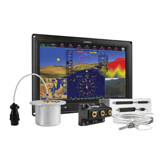
Page 15: Inventory Of Materials
All materials that are required/optional for the installation of the G3X are listed in this section (as such, some of the information in this section is repeated in following sections). -
Page 16: Optional Garmin Equipment
010-01056-00 G3X Touch - GDU 455, 7” Landscape Display with SXM Receiver 010-01056-10 *Any combination of G3X Touch displays can be installed in a single system (maximum of six displays) **Not compatible with G3X Touch displays 1.3 Optional Garmin Equipment 1.3.1... - Page 17 Contact, Sckt, Mil Crimp, size 20, 20-24 AWG 336-00022-02 1.3.2 GPS/XM Antenna(s) A Garmin or non-Garmin GPS antenna is required for a G3X installation. A Garmin or non-Garmin XM antenna is required for G3X installations using SiriusXM® weather. See Section 20 for required materials for antenna installation including mounting brackets, doubler plates, rivets, hardware, cables, connectors, and sealant.
-
Page 18: Optional Garmin Lrus
1.4 Optional Garmin LRUs Table 1-7 lists optional Garmin LRUs that can be installed with the G3X system. If any of these LRUs are to be used in this installation, verify that all required installation materials such as connector kits have been acquired. -
Page 19: Required Non-Garmin Equipment
Clamps (Adel Clamp) - Various sizes for routing new wiring in the engine cowl (MS21919WDGXX). Coaxial Cable, 50Ω - MIL-DTL-17 (i.e. RG-400) Current Shunts - Qualified to AA55524 Environmental Splice - AS81824/1-X (where X=size) or equivalent Fiberglass Sleeving - Qualified to MIL-I-3190/6 190-01115-01 G3X™/G3X Touch™ Avionics Installation Manual Rev. AV Page 1-5... - Page 20 AS83519/1-X, AS83519/2-X or equivalent • AS83519/X-2 for single conductor wire • AS83519/X-3 for twisted-pair and triple conductor wire • AS83519/X-4 for RG-400 coax Silicone Fusion Tape - A-A-59163 (MIL-I-46852C or equivalent) 190-01115-01 G3X™/G3X Touch™ Avionics Installation Manual Rev. AV Page 1-6...
- Page 21 150°C or higher - Stranded AWG 24-20, colored per ASTM E 230, and tested in accordance with at least one of the following STDS: • ASTM E 207 • ASTM E 220 • AMS 2750 (e.g. Watlow, SERV-RITE P/Ns K24-3-507 and J20-3-507) 190-01115-01 G3X™/G3X Touch™ Avionics Installation Manual Rev. AV Page 1-7...
- Page 22 1.5.2 Contact and Crimp Tools Table 1-8 lists recommended crimp tools used to build the wiring harnesses for the G3X LRUs, other equivalent tooling may also be used. Table 1-8 Pin Contact and Crimp Tools Part Numbers Garmin Recommended Recommended...
- Page 23 SD Card An SD Card is required to be used as a DataCard. Garmin recommends a 2 GB SanDisk® brand SD card for GDU 37X units, and an 8 GB SanDisk® brand SD card for GDU 4XX units. SD or SDHC cards up to 32 GB using the FAT32 file format are supported, SDXC and SDUC cards are not supported.
-
Page 24: Optional Garmin Equipment (Non-Lru)
Antenna Brackets/Doubler Plates Section 20 for detailed information. 1.6.3 Silicon Fusion Tape Garmin Part Number 249-00114-00 or similar, used to wrap the wiring/cable bundles. 1.7 Optional non-Garmin Equipment 1.7.1 Engine/Airframe Sensors Section 21.1 for a list of compatible sensors, and Section 21.3... -
Page 25: Installation Preparation
GMC control panel) or in a separate avionics bay if desired. This design greatly eases troubleshooting and maintenance of the G3X system. A failure or problem can be isolated to a particular LRU, which can be replaced quickly and easily. Each LRU has a particular function, or set of functions, that contributes to the system’s operation. - Page 26 An individual device in the G3X system is often referred to as a “Line Replaceable Unit”, or LRU. This term is used generically in aviation for devices that can be readily “swapped out” for troubleshooting or repair.
- Page 27 2.1.1.1 Displays The foundation of a G3X system is one or more GDU display units. A GDU display is configured with wiring connections as either a primary flight display (PFD) or multi-function display (MFD), with options for arranging display layouts and combining different types of data on a single display. In the event that power is removed from a GDU display, important flight data can still be accessed on the remaining display(s).
- Page 28 ADAHRS unit. In a G3X Touch system installed with no dedicated ADAHRS units, attitude and air data from the G5 will be used throughout the system, including for autopilot functionality, but will not be visible on the GDU 4XX displays.
- Page 29 In a G3X Touch system with one or more G5 displays but no ADAHRS units, a GTP 59 can optionally be connected by the GAD 13 temperature probe adapter. If the system is later expanded with the addition of one or more ADAHRS units, the GAD 13 may be retained, or the GAD 13 may be removed and the GTP 59 connected to the #1 GSU 25 ADAHRS unit.
- Page 30 The GPS 20A is a TSO-compliant WAAS GPS position source that is compatible with the G3X system. The GPS 20A provides GPS data to the G3X system using the CAN bus, and can send ADS-B position data to a transponder using RS-232. For GPS 20A installation information and a list of supported GPS...
- Page 31 GPS 175, or GTN 6XX/7XX IFR GPS navigator, allowing VFR flight plans to be created on the G3X system and uploaded to the IFR navigator. The GDU 4XX display in a G3X Touch system can also act as a relay between the GNC 355, GNS 4XX/5XX, GNX 375, GPS 175, and GTN 6XX/7XX IFR GPS...
- Page 32 Supported Garmin panel-mount COM radios can be controlled either using the GDU displays or through their own front-panel controls. The GTR 20 is a remote-mounted COM radio that is entirely controlled by the G3X Touch display, with no front-panel interface. For GTR 20 installation information, refer to...
- Page 33 In a G3X system with a transponder and a GTN, the transponder is typically controlled by the G3X system, not the GTN. Note the GTX 23ES and GTX 35R/45R can only be controlled by the G3X system, not by the GTN.
- Page 34 Section The GMC 507 is physically similar to the GMC 307, but it connects to the G3X system through the shared CAN bus. Up to two GMC 507 Mode Control panels can be installed. The GMC 507 adds an additional flight director mode button.
- Page 35 FIS-B weather data can be provided to GDU displays from a GDL 39R remote-mounted ADS-B receiver. The GDL 39R can be connected to a single GDU display using RS-232. In a G3X Touch system, the GDL 39R may also be connected to additional GDU 4XX displays wirelessly using Bluetooth.
- Page 36 GTX transponder. TIS-A traffic data can be provided by GTX 23ES, 33, 330, and GTX 335/335R transponders. Traffic data is provided to the G3X system using the CAN bus from the #1 ADAHRS unit, to which the transponder is connected.
- Page 37 • A G3X Touch system with GDU 4XX displays may be connected using the CAN bus to the GMA™ 245/245R audio panel, allowing full control of audio panel functionality from the GDU display.
- Page 38 Garmin Pilot or another application that supports the Garmin Connext protocol. In a G3X Touch system with a GDL 39R ADS-B receiver, the primary connection between the GDL and a single GDU 4XX display is through RS-232. However, Bluetooth may also be used to connect additional GDU 4XX displays to the GDL 39R, in order to view FIS-B weather data on multiple displays.
- Page 39 Smart Glide is designed to assist the pilot by enhancing situational awareness and providing helpful automation during an emergency inoperative engine event. The G3X Touch is capable of providing this assistance internally, without the need for an external navigator. Upon activation, Smart Glide assists the pilot with three critical components of a safe recovery from an engine failure: •...
-
Page 40: Electrical Considerations
LRU before handling the LRU itself. 2.2.1 Power Specifications All G3X LRUs are capable of operating at either 14 or 28 VDC (except the GAD 27 which is 14 VDC only, and the GAP 26, see Note in Section 5). Table 2-1 and... - Page 41 28 Vdc 0.067 A (67 mA) *Garmin recommends using Mod 1 level GSU 73 in aircraft that use a +28 V supply voltage and intend to monitor current on high voltage devices such as the aircraft alternator. **The specified current draw is measured with the display backlight set to 100% 190-01115-01 G3X™/G3X Touch™...
- Page 42 3.75 Amp, Maximum, 90% modulated into 3:1 VSWR and 22 V power input voltage *Garmin recommends using Mod 1 level GSU 73 in aircraft that use a +28 V supply voltage and intend to monitor current on high voltage devices such as the aircraft alternator.
-
Page 43: Wiring/Cabling Considerations
Table 1-8 lists contact part numbers (for reference) and recommended crimp tools. CAUTION Check wiring connections for errors before connecting any wiring harnesses. Incorrect wiring could cause internal component damage. 190-01115-01 G3X™/G3X Touch™ Avionics Installation Manual Rev. AV Page 2-19... - Page 44 Section 2.3.1.2 Configuration Module The G3X system is designed to store configuration and calibration data in multiple locations to retain the configuration of the system during maintenance. A configuration module (Figure 2-2 and Figure 2-3) is installed in the connector backshell of the PFD1 display to store important configuration data. Only the PFD1 display uses a configuration module;...
- Page 45 CAN bus from end to end should be 20 meters (66 feet) or less. At each of the two extreme ends of the CAN bus, a 120 Ω resistor is installed to “terminate” the bus. In the G3X system, termination resistors are...
- Page 46 CAN bus should instead be daisy chained from one device to the next (Figure 2-6). Max. node length 0.3 meter (1 ft) Figure 2-6 Node Connections 190-01115-01 G3X™/G3X Touch™ Avionics Installation Manual Rev. AV Page 2-22...
- Page 47 The layout of the CAN bus must be a single linear backbone with exactly two distinct end points (Figure 2-7). Other layouts such as “star” or “Y” arrangements must be avoided. Similarly, hub devices must not be used with the G3X CAN bus. (Figure 2-8) LINEAR CAN BACKBONE, DAISY-CHAINED CONNECTIONS WITH SHORT STUB NODE LENGTHS.
- Page 48 CAN bus. 190-01115-01 G3X™/G3X Touch™ Avionics Installation Manual Rev. AV Page 2-24...
- Page 49 Connect all LRU power ground pins to a single common ground point - do not use local ground points or use the aircraft structure as a ground return path. 190-01115-01 G3X™/G3X Touch™ Avionics Installation Manual Rev. AV Page 2-25...
- Page 50 At each of the two extreme ends of the CAN bus backbone, a 120 Ω resistor is installed to terminate the bus. In the G3X system, separate resistors are not required. Instead, termination resistors are provided either within the LRUs themselves, or using termination adapters that plug into an LRU’s CAN connection.
- Page 51 Figure 2-14 Correct CAN Bus Termination Example TERM INCORRECT - ONE OF THE TERMINATIONS IS NOT AT END OF BACKBONE INCORRECT - ONLY ONE END OF BACKBONE IS TERMINATED Figure 2-15 Incorrect CAN Bus Termination Examples 190-01115-01 G3X™/G3X Touch™ Avionics Installation Manual Rev. AV Page 2-27...
- Page 52 2.3.1.3.4 CAN Bus LRU Removal Guidelines The following should be considered when removing an LRU from the ends of G3X CAN network: • GEA 24, GSU 25, GAD 29, GPS 20A, G5, or other devices that uses the 9-pin CAN termination adapter: The CAN bus will remain terminated as long as the CAN termination adapter is left connected.
- Page 53 9. It is very important for each device on the CAN bus to share a common power/signal ground. Ground potential differences between devices on the CAN bus can cause communication errors. Ground devices to a common ground bus, not to the airframe or to multiple grounding buses. 190-01115-01 G3X™/G3X Touch™ Avionics Installation Manual Rev. AV Page 2-29...
-
Page 54: Mechanical Considerations
GDU 37X, GDU 45X, GDU 46X, GDU 470, GMC 305, and GMC 307 in the respective LRU sections of this document. Cutout templates for the GDU 37X/4XX displays and the GMC 507 are also available in digital form (.DXF files) from the G3X manuals download page on www.garmin.com. - Page 55 Table 2-4 G3X LRU Physical Specifications Weight of Unit Width Height Depth Unit Weight and Connector(s) **-20 probe with Probe Probe -20 probe: 6.12 inches adjustable .82 inches 16.0 inches 0.39 lbs [157.7 mm] mounting kit: [20.9 mm] [406.4 mm] (0.18 kg)
- Page 56 Table 2-4 G3X LRU Physical Specifications Weight of Unit Width Height Depth Unit Weight and Connector(s) 10.85 GDU 465 7.82 inches 3.57 inches 4.73 lbs inches 4.94 lbs*, (2.24 kg) (Display) (198.6 mm) (90.7 mm) (2.15 kg) (275.5 mm) Depth behind panel including 6.01 inches...
- Page 57 Table 2-4 G3X LRU Physical Specifications Weight of Unit Width Height Depth Unit Weight and Connector(s) Refer to Table 16- GSA 28 2.5 inches 4.0 inches 1.40 lbs 2.8 inches (71.1 mm) for connector/ (Servo (63.5 mm) (101.6 mm) (0.635 kg)
-
Page 58: Lru/Sensor Installation Information
Cooling Requirements While no forced cooling air is required for the G3X system, it is highly recommended the air behind the panel be kept moving (by ventilation or a fan). Units tightly packed in the avionics stack heat each other through radiation, convection, and sometimes by direct conduction. -
Page 59: Gad 27 (Flaps/Lights/Trim Controller) Installation
Middle position in the downwind. Similarly, after turning final, the pilot can bump the switch downward again and the GAD 27 will automatically extend the flaps to the full down position. Since the GAD 27 receives airspeed from the G3X Touch™ avionics, it can also prevent flap extension when the 190-01115-01 G3X™/G3X Touch™... - Page 60 Provides a 12V power bus output to keep essential avionics online during engine start when battery voltage drops. 3.1.1 Status LED The GAD 27 has an LED on its outer case that indicates its current status. See Section 31.1.1 for details. 190-01115-01 G3X™/G3X Touch™ Avionics Installation Manual Rev. AV Page 3-2...
-
Page 61: Equipment Available
3. Connect backshell connectors. 4. Screw down ring terminals to terminal block. The screws in the terminal block should be removed, the ring terminal inserted, and then the screw replaced. 190-01115-01 G3X™/G3X Touch™ Avionics Installation Manual Rev. AV Page 3-3... -
Page 62: Outline And Installation Drawings
DIMENSIONS ARE SHOWN FOR REFERENCE ONLY. 3.569 1.723 .984 CENTER OF GRAVITY 3.215 .100 .040 CENTER OF GRAVITY 3.780 TYPICAL THICKNESS 4.687 BENEATH FASTENER HEAD 5.204 Figure 3-2 GAD 27 Outline Drawing 190-01115-01 G3X™/G3X Touch™ Avionics Installation Manual Rev. AV Page 3-4... - Page 63 P272 GAD 27 011-01855-01 CONNECTOR KIT 011-03877-00 330-00625-15 GAD 27 011-03876-X0 J272 TB273 J271 GAD 27 CONNECTOR KIT 011-03877-00 330-00625-50 P271 011-01855-04 Figure 3-3 GAD 27 Installation Drawing 190-01115-01 G3X™/G3X Touch™ Avionics Installation Manual Rev. AV Page 3-5...
-
Page 64: Gad 29/29B/29C/29D (Arinc 429 Adapter) Installation
The GAD 29B was a prior version of the GAD 29D, all form, fit, and functions are identical for the two models. J292 J292 J291 J291 Figure 4-1 GAD 29 Unit View 190-01115-01 G3X™/G3X Touch™ Avionics Installation Manual Rev. AV Page 4-1... -
Page 65: Equipment Description
4.1 Equipment Description The GAD 29 allows the G3X™ avionics to interface to IFR navigators such as the GNC® radio, GNS™ receiver, GNX™ IFR navigator, GPS and GTN™ touchscreen avionics. The GAD 29 has a 25 pin D-sub connector and a 9 pin D-sub connector. These connectors will provide the following functionality: •... -
Page 66: General Specifications
1. Mount the unit to a suitable mounting location using (4) #10-32 pan or hex head screws. 2. Assemble the connector backshells and wiring harness. 3. Connect CAN terminator to unit if required (Section 2.3.1.3.3). 4. Connect backshell connectors. 190-01115-01 G3X™/G3X Touch™ Avionics Installation Manual Rev. AV Page 4-3... -
Page 67: Outline And Installation Drawings
4.6 Outline and Installation Drawings Figure 4-2 GAD 29 Outline Drawing 190-01115-01 G3X™/G3X Touch™ Avionics Installation Manual Rev. AV Page 4-4... - Page 68 Figure 4-3 GAD 29 Installation Drawing (no CAN terminator) 190-01115-01 G3X™/G3X Touch™ Avionics Installation Manual Rev. AV Page 4-5...
- Page 69 Figure 4-4 GAD 29 Installation Drawing (with CAN terminator) 190-01115-01 G3X™/G3X Touch™ Avionics Installation Manual Rev. AV Page 4-6...
-
Page 70: Gap 26 (Pitot/Aoa Probe) Installation
The function of the GAP 26 is to provide pitot and AOA pressures to the GSU 25 for the purpose of displaying airspeed and AOA to the pilot as part of the G3X system. The GAP 26 does not provide a static pressure source to the GSU 25. -
Page 71: Equipment Available
GAP 26 Adjustable Mount, Washer Plate 115-02075-00 GAP 26 Adjustable Mount, Tube Bracket 117-00659-00 GAP 26 AN5812 Mount Tube, Aluminum 117-02013-00 5.3 General Specifications Section 2.2 for power/current specifications, and Section 2.4.1 for dimension/weight specifications. 190-01115-01 G3X™/G3X Touch™ Avionics Installation Manual Rev. AV Page 5-2... -
Page 72: Mounting Requirements
AC 43.13-2B Chapters 1 and 3. In addition, the installer must show the installation is adequate for expected loading and does not affect the surrounding structure of the aircraft. 190-01115-01 G3X™/G3X Touch™ Avionics Installation Manual Rev. AV Page 5-3... - Page 73 Figure 5-2. GAP 26 Probe and Mount (Side View) Max distance from mounting hole centerline to edge of doubler is 1.5” Figure 5-3. GAP 26 Shown with Inspection Panel and Doubler Plate 190-01115-01 G3X™/G3X Touch™ Avionics Installation Manual Rev. AV Page 5-4...
-
Page 74: Unit Installation
• Garmin recommends the GAP 26 not be used on aircraft where the ship static pressure port is located under the wing (due to the likelihood the AOA measurement will be significantly impacted). - Page 75 “banded” (Figure 5-5) to help identify individual heaters. These heaters can be connected to a power source as shown in Figure 5-6 and Figure 5-7. “Banded” Wire Figure 5-5 GAP 26 Banded Wire 190-01115-01 G3X™/G3X Touch™ Avionics Installation Manual Rev. AV Page 5-6...
- Page 76 Do not connect the heaters in parallel to 28V. See Figure 5-7 for use on 28V aircraft. The heaters will be damaged if connected incorrectly to 28V. Figure 5-6 GAP 26, 14V Installation Configuration (010-01074-10 only) Figure 5-7 GAP 26, 28V Installation Configuration (010-01074-10 only) 190-01115-01 G3X™/G3X Touch™ Avionics Installation Manual Rev. AV Page 5-7...
- Page 77 RED WIRE (BARE) RED WIRE (BARE) BLACK WIRE (BARE) BLACK WIRE (BARE) BLACK WIRE (BARE) BLACK WIRE (BARE) Figure 5-8 011-02964-20 Probe Wiring Figure 5-9 011-02964-20 Probe to Control Box Connectors 190-01115-01 G3X™/G3X Touch™ Avionics Installation Manual Rev. AV Page 5-8...
- Page 78 This loss is not to exceed 10 knots/min. While some GAP 26 probes will pass a test of this type, some may not. Garmin has determined that a leak rate of 250 knots/min or less is allowable and still provides proper functionality.
- Page 79 5.6 Outline and Installation Drawings Figure 5-10 GAP 26 Outline Drawing 190-01115-01 G3X™/G3X Touch™ Avionics Installation Manual Rev. AV Page 5-10...
- Page 80 Figure 5-11 GAP 26 Heater Control Box (used with -20 unit only) 190-01115-01 G3X™/G3X Touch™ Avionics Installation Manual Rev. AV Page 5-11...
-
Page 81: Gdu™ 4Xx Display Installation
This section contains general information as well as installation information for the GDU 4XX units. Use this section to mount the GDU 45X/46X/470 unit(s). Figure 6-1 GDU 45X Unit View Figure 6-2 GDU 46X Unit View 190-01115-01 G3X™/G3X Touch™ Avionics Installation Manual Rev. AV Page 6-1... -
Page 82: Equipment Description
GDU 4XX displays us invisible infrared beams for touch detection, this makes it very important to keep the screen clean, especially along the edges. NOTE Section 32.2.1.5 for information on replacing a GDU 37X display with a GDU 4XX display. 190-01115-01 G3X™/G3X Touch™ Avionics Installation Manual Rev. AV Page 6-2... -
Page 83: General Specifications
6.1.2 Interface Summary NOTE A G3X™ avionics installation can use either GDU 37X or GDU 4XX displays, but a G3X system installation cannot use GDU 37X and GDU 4XX displays. NOTE If upgrading from a GDU 37X to a GDU 4XX display, refer to upgrade instructions in Section 32.2.1.5... -
Page 84: Installation Information
Table 6-4 Contents of GDU 4XX Connector Kit (011-01921-10) Item Garmin P/N Quantity Sub-Assy, bkshl w/Hdw, Jackscrew 011-01855-04 Conn, Rcpt, D-Sub, Crimp Socket 330-00625-50 Contact, Sckt, D-Sub, Crimp, Size 20 336-00022-02 190-01115-01 G3X™/G3X Touch™ Avionics Installation Manual Rev. AV Page 6-4... -
Page 85: Unit Installation
The instructions needed to assemble the backshell connector w/Shield Block grounding system are located in Section Replacement cursor knobs (part number K00-00578-00) for the GDU 4XX are available from a Garmin dealer. 6.5 Antennas... -
Page 86: Mounting Requirements
The corners of the existing GDU 37X panel cutout must be slightly enlarged using the drilling guide as a template. The nut plate is then used to mount the GDU 470 to the updated panel opening. 190-01115-01 G3X™/G3X Touch™ Avionics Installation Manual Rev. AV Page 6-6... -
Page 87: Gdu 45X Outline And Installation Drawings
GDU 45X Outline and Installation Drawings Figure 6-4 GDU 45X Outline Drawing 190-01115-01 G3X™/G3X Touch™ Avionics Installation Manual Rev. AV Page 6-7... - Page 88 Figure 6-5 GDU 45X Assembly Drawing 190-01115-01 G3X™/G3X Touch™ Avionics Installation Manual Rev. AV Page 6-8...
- Page 89 Figure 6-6 GDU 45X Panel Cutout Drawing (not to scale) 190-01115-01 G3X™/G3X Touch™ Avionics Installation Manual Rev. AV Page 6-9...
-
Page 90: Gdu 46X Outline And Installation Drawings
GDU 46X Outline and Installation Drawings Figure 6-7 GDU 46X Outline Drawing 190-01115-01 G3X™/G3X Touch™ Avionics Installation Manual Rev. AV Page 6-10... - Page 91 Figure 6-8 GDU 46X Assembly Drawing 190-01115-01 G3X™/G3X Touch™ Avionics Installation Manual Rev. AV Page 6-11...
- Page 92 Figure 6-9 GDU 46X Panel Cutout Drawing (not to scale) 190-01115-01 G3X™/G3X Touch™ Avionics Installation Manual Rev. AV Page 6-12...
-
Page 93: Gdu 470 Outline And Installation Drawings
GDU 470 Outline and Installation Drawings Figure 6-10 GDU 470 Outline Drawing 190-01115-01 G3X™/G3X Touch™ Avionics Installation Manual Rev. AV Page 6-13... - Page 94 Figure 6-11 GDU 470 Assembly Drawing 190-01115-01 G3X™/G3X Touch™ Avionics Installation Manual Rev. AV Page 6-14...
- Page 95 2X 3.31 84.0 4X .29 7.4 5.48 139.1 7.30 185.5 0 0.0 2X 3.35 85.2 3.65 92.8 2X 3.68 93.5 Figure 6-12 GDU 470 Panel Cutout Drawing (not to scale) 190-01115-01 G3X™/G3X Touch™ Avionics Installation Manual Rev. AV Page 6-15...
-
Page 96: Panel Cutout Drawings
5.39 in (#36) / tap (6/32) to create threaded holes [137.0 mm] [137.0 mm] drill out with #25 drill bit and use Garmin nut-plate P/N 115-01725-00. The outline in this drawing is identical to the outline of the actual bezel. - Page 97 (#36) / tap (6/32) to create threaded holes Cut out panel to inside line 7.29 in 7.29 in drill out with #25 drill bit and use Garmin 185.10 mm 185.10 mm nut-plate P/N 115-01725-01. The outline in this drawing is identical to the outline of the actual bezel.
- Page 98 For corner holes, center punch and drill (#36) / tap (6/32) to create threaded holes drill out with #25 drill bit and use Garmin nut-plate P/N 115-01725-03. The outline in this drawing is identical to the outline of the actual bezel.
-
Page 99: Gea™ 24 Engine Interface Module Installation
Experimental – Amateur Built (E-AB) and Light Sport Aircraft (LSA) markets. In a G3X™ avionics or G3X Touch™ avionics system, two GEA 24 units may be installed to monitor and display engine data for twin-engine aircraft, or single-engine aircraft with more than six cylinders. The second GEA 24 must be... -
Page 100: Equipment Available
Conn, Rcpt, D-Sub, Crimp Socket, Commercial, 37 CKT 330-00625-37 Conn, Rcpt, D-Sub, Crimp Socket, Commercial, 50 CKT 330-00625-50 Contact, Socket, Military Crimp, Size 20 336-00022-02 Contact ,Pin, Military Crimp, Size 20 336-00024-00 190-01115-01 G3X™/G3X Touch™ Avionics Installation Manual Rev. AV Page 7-2... -
Page 101: General Specifications
23.4 for pinouts. The GEA 24 connects to other LRUs in the G3X system using the CAN bus. To provide an optional redundant path for engine data, a secondary RS-232 connection to a single GDU™ display is also supported. See Figure 24-1.11... -
Page 102: Outline And Installation Drawings
Outline and Installation Drawings Figure 7-2 GEA 24 Outline Drawing 190-01115-01 G3X™/G3X Touch™ Avionics Installation Manual Rev. AV Page 7-4... - Page 103 Figure 7-3 GEA 24 Assembly Drawing (no CAN terminator) 190-01115-01 G3X™/G3X Touch™ Avionics Installation Manual Rev. AV Page 7-5...
- Page 104 Figure 7-4 GEA 24 Assembly Drawing (with CAN terminator) 190-01115-01 G3X™/G3X Touch™ Avionics Installation Manual Rev. AV Page 7-6...
-
Page 105: Gha 15 Height Advisor Installation
Table 8-3 Contents of GHA 15 Connector Kit (011-05278-00) Item Garmin P/N Quantity Conn,Circ, Plug, D38999/26, Ins 13- 35, Alum,Crimp, Key A 330-01288-01 Conn Seal Plug, MS27488-22 330-90013-01 Backshell, Circular, Strain Relief, AS85049/126, RA, Size 13 330-90049-03 190-01115-01 G3X™/G3X Touch™ Avionics Installation Manual Rev. AV Page 8-1... -
Page 106: General Specifications
1 amp aircraft circuit breakers are recommended Circuit Breakers (1 per installation) for 28 VDC operation. 8.3 General Specifications Section 2.2 for power/current specifications, and Section 2.4.1 for dimension/weight specifications. 190-01115-01 G3X™/G3X Touch™ Avionics Installation Manual Rev. AV Page 8-2... -
Page 107: Mounting Requirements
(removable). If the aircraft is not equipped with mounting provisions, refer to AC 43.13-2B for guidance on manufacturing and installing doublers. 8.4.2 Grounding Grounding of the GHA 15 is necessary for equipment operation. NOTE Good electrical bonding is important. 190-01115-01 G3X™/G3X Touch™ Avionics Installation Manual Rev. AV Page 8-3... -
Page 108: Unit Installation
Do not use construction grade RTV sealant or sealants containing acetic acid. These sealants may damage the electrical connections to the antenna. Use of these type sealants may void the antenna warranty. 190-01115-01 G3X™/G3X Touch™ Avionics Installation Manual Rev. AV Page 8-4... -
Page 109: Outline And Installation Drawings
8.6 Outline and Installation Drawings Figure 8-1 GHA 15 Outline Drawing 190-01115-01 G3X™/G3X Touch™ Avionics Installation Manual Rev. AV Page 8-5... -
Page 110: Gi 260 (Aoa Indicator) Installation
The GI 260 Socket Mount (011-03562-00) is included with the unit. The Socket Mount is secured using (3) #6-32 100º flat head screws be supplied by the installer. 9.3 General Specifications Section 2.2 for power/current specifications, and Section 2.4.1 for dimension/weight specifications. 190-01115-01 G3X™/G3X Touch™ Avionics Installation Manual Rev. AV Page 9-1... -
Page 111: Unit Installation
Stall Warning (red) or Caution Alert (yellow) conditions have returned to a Minimum Visible (green) condition. The mute operation is then reset, and audio is unmuted. Stall Warning Caution Alert Approach Target AOA Minimum Visible AOA Figure 9-2 GI 260 Display 190-01115-01 G3X™/G3X Touch™ Avionics Installation Manual Rev. AV Page 9-2... -
Page 112: Outline And Installation Drawings
Outline and Installation Drawings Figure 9-3 GI 260 Outline/Assembly Drawing 190-01115-01 G3X™/G3X Touch™ Avionics Installation Manual Rev. AV Page 9-3... -
Page 113: Section 10 Gmc 305 (Afcs Mode Controller) Installation
Figure 10-1 GMC 305 Unit View (-20 version shown, -00 version has no YD button) 10.1 Equipment Description The GMC 305 is a Garmin Automatic Flight Control System (AFCS) Mode Controller that can be used in a G3X™ avionics installation. The GMC 305 provides a user interface for the autopilot function of the G3X system. -
Page 114: General Specifications
Dimensions on the figure are to verify accuracy of printout only, see Figure 10-4 for complete cutout dimensions. A .dxf version of the drawing is also available for download at https://support.garmin.com/support/manuals. 190-01115-01 G3X™/G3X Touch™ Avionics Installation Manual Rev. AV... - Page 115 24-1.7). The selected GDU RS-232 channel must be configured for “Garmin Instrument Data”. If the installation includes a Garmin integrated autopilot using GSA 28 servos, the GMC 305 installation also includes an RS-232 connection to the GSA 28 roll servo (Figure 24-1.7).
-
Page 116: Outline And Installation Drawings
10.5 Outline and Installation Drawings Figure 10-2 GMC 305 Outline Drawing 190-01115-01 G3X™/G3X Touch™ Avionics Installation Manual Rev. AV Page 10-4... - Page 117 Figure 10-3 GMC 305 Installation Drawing 190-01115-01 G3X™/G3X Touch™ Avionics Installation Manual Rev. AV Page 10-5...
- Page 118 Figure 10-4 GMC 305 Cutout Drawing (Not to Scale) 190-01115-01 G3X™/G3X Touch™ Avionics Installation Manual Rev. AV Page 10-6...
- Page 119 NOTES: DIMENSIONS: INCHES[mm]. METRIC VALUES ARE FOR REFERENCE ONLY. DIMENSIONS ARE NOMINAL AND TOLERANCES ARE NOT IMPLIED UNLESS SPECIFICALLY STATED. Figure 10-5 GMC 305 Panel Cutout Template 190-01115-01 G3X™/G3X Touch™ Avionics Installation Manual Rev. AV Page 10-7...
-
Page 120: Section 11 Gmc 307 (Afcs Mode Controller) Installation
Figure 11-1 GMC 307 Unit View (-00 version shown, -20 version has no YD button) 11.1 Equipment Description The GMC 307 is a Garmin Automatic Flight Control System (AFCS) Mode Controller that can be used in a G3X™ avionics installation. The GMC 307 provides a user interface for the autopilot function of the G3X system. -
Page 121: General Specifications
Dimensions on the figure are to verify accuracy of printout only, see Figure 11-5 for complete cutout dimensions. A .dxf version of the drawing is also available for download at https://support.garmin.com/support/manuals. 190-01115-01 G3X™/G3X Touch™ Avionics Installation Manual Rev. AV... - Page 122 24-1.7). The selected GDU RS-232 channel must be configured for “Garmin Instrument Data”. If the installation includes a Garmin integrated autopilot using GSA 28 servos, the GMC 307 installation also includes an RS-232 connection to the GSA 28 roll servo (Figure 24-1.7).
-
Page 123: Outline And Installation Drawings
11.5 Outline and Installation Drawings Figure 11-3 GMC 307 Outline Drawing 190-01115-01 G3X™/G3X Touch™ Avionics Installation Manual Rev. AV Page 11-4... - Page 124 Figure 11-4 GMC 307 Installation Drawing 190-01115-01 G3X™/G3X Touch™ Avionics Installation Manual Rev. AV Page 11-5...
- Page 125 Figure 11-5 GMC 307 Cutout Drawing (Not to Scale) 190-01115-01 G3X™/G3X Touch™ Avionics Installation Manual Rev. AV Page 11-6...
- Page 126 (REF.) NOTES: 1. DIMENSIONS: INCHES [mm]. METRIC VALUES ARE FOR REFERENCE ONLY. 2. TOLERANCES: INCH .XX ±.02 .X ±0.5 .XXX ±.010 .XX ±0.25 Figure 11-6 GMC 307 Panel Cutout Template 190-01115-01 G3X™/G3X Touch™ Avionics Installation Manual Rev. AV Page 11-7...
-
Page 127: Section 12 Gmc 507 (Afcs Mode Controller) Installation
G3X™ avionics installation. Up to two GMC 507 Mode Controllers may be installed. The GMC 507 provides a user interface for the autopilot function of the G3X system. The GMC 507 mounts flush to the aircraft instrument panel using two pawl latches or may be mounted in the radio stack using the optional... -
Page 128: General Specifications
Figure 12-5 for complete cutout dimensions. A .dxf version of the drawing is also available for download at https://support.garmin.com/support/manuals. CAUTION Exercise caution when installing the rack in the instrument panel. Deformation of the rack will make it difficult to install and remove the GMC 507. - Page 129 12.3.3 Wiring The 15 pin connector, pins, and backshell supplied in the GMC 507 installation kit are used to add wiring for the GMC 507. Figure 24-1.8 for example interconnect drawing. 190-01115-01 G3X™/G3X Touch™ Avionics Installation Manual Rev. AV Page 12-3...
-
Page 130: Outline And Installation Drawings
12.4 Outline and Installation Drawings Figure 12-3 GMC 507 Outline Drawing (no installation rack) 190-01115-01 G3X™/G3X Touch™ Avionics Installation Manual Rev. AV Page 12-4... - Page 131 Figure 12-4 GMC 507 Installation Drawing (no installation rack) 190-01115-01 G3X™/G3X Touch™ Avionics Installation Manual Rev. AV Page 12-5...
- Page 132 Figure 12-5 GMC 507 Cutout Drawing, No Installation Rack (Not to Scale) 190-01115-01 G3X™/G3X Touch™ Avionics Installation Manual Rev. AV Page 12-6...
- Page 133 1. DIMENSIONS: INCHES [mm]. METRIC VALUES ARE FOR REFERENCE ONLY. 2. TOLERANCES: INCH .XX ±.02 .X ±0.5 .XXX ±.010 .XX ±0.25 Figure 12-6 GMC 507 Panel Cutout Template (no installation rack) 190-01115-01 G3X™/G3X Touch™ Avionics Installation Manual Rev. AV Page 12-7...
- Page 134 Figure 12-7 GMC 507 Outline Drawing with Installation Rack 190-01115-01 G3X™/G3X Touch™ Avionics Installation Manual Rev. AV Page 12-8...
- Page 135 Figure 12-8 GMC 507 Installation Drawing with Installation Rack 190-01115-01 G3X™/G3X Touch™ Avionics Installation Manual Rev. AV Page 12-9...
- Page 136 Figure 12-9 GMC 507 Panel Cutout Template for Installation with Installation Rack 190-01115-01 G3X™/G3X Touch™ Avionics Installation Manual Rev. AV Page 12-10...
-
Page 137: Section 13 Gmu 11 (Magnetometer) Installation
GMU 11 unit. Figure 13-1 GMU 11 Unit View 13.1 Equipment Description The GMU 11 magnetometer is a remote mounted device that provides magnetometer data to a Garmin GSU 25 ADAHRS. The Garmin ADAHRS and magnetometer replace traditional rotating mass instruments. -
Page 138: Equipment Available
If the requirements listed in Table 13-4 cannot be met, a magnetometer interference test must be performed to make sure of proper operation of the G3X™ avionics system. Refer to the AHRS/Magnetometer Installation Considerations document (190-01051-00) available from the Garmin website (www.garmin.com... - Page 139 13-4, align the GMU 11’s forward direction to within 0.5° of the any of the 4 cardinal directions with relation between its connector and the nose of the aircraft. Make sure the bottom of the unit is facing downwards (towards earth) per Figure 13-4. 190-01115-01 G3X™/G3X Touch™ Avionics Installation Manual Rev. AV Page 13-3...
- Page 140 (e.g. beryllium copper or titanium) is recommended when installing or servicing the GMU 11. Do not use a screwdriver that contains a magnet when installing or servicing the GMU 11. Refer to Section 13.5 for outline and installation drawings. 190-01115-01 G3X™/G3X Touch™ Avionics Installation Manual Rev. AV Page 13-4...
-
Page 141: Outline And Installation Drawings
13.5 Outline and Installation Drawings 2.74 2.28 0.93 1.37 0.38 Figure 13-2 GMU 11 Outline Drawing 190-01115-01 G3X™/G3X Touch™ Avionics Installation Manual Rev. AV Page 13-5... - Page 142 Figure 13-3 GMU 11 Installation Drawing 190-01115-01 G3X™/G3X Touch™ Avionics Installation Manual Rev. AV Page 13-6...
- Page 143 Figure 13-4 GMU 11 Orientation Drawing 190-01115-01 G3X™/G3X Touch™ Avionics Installation Manual Rev. AV Page 13-7...
-
Page 144: Section 14 Gmu 22 (Magnetometer) Installation
GMU 22 into specific experimental airframes. Figure 14-1 GMU 22 Unit View 14.1 Equipment Description The GMU 22 magnetometer is a remote mounted device that provides magnetometer data to Garmin ADAHRS devices (GSU 25/73). The Garmin ADAHRS and magnetometer replace traditional rotating mass instruments. -
Page 145: General Specifications
Modified Install Rack 115-00481-10 Screw, 6-32x .250, Pan Head Phillips, Brass, w/Nylon 211-60037-08 Circular Connector, Female, 9 Ckt 330-00360-00 Circular non-Magnetic Backshell 330-90005-01 Socket Contact Mil Crp, Size 20 336-00022-00 190-01115-01 G3X™/G3X Touch™ Avionics Installation Manual Rev. AV Page 14-2... -
Page 146: Unit Installation
If the requirements listed in Table 14-4 cannot be met, a magnetometer interference test must be performed to make sure of proper operation of the G3X system. Refer to the AHRS/Magnetometer Installation Considerations document (190-01051-00) available from the Garmin website (www.garmin.com... - Page 147 GMU 22 units for other GSU 25 ADAHRS units is optional. An ADAHRS without a GMU 22 connected will use magnetometer data supplied by other ADAHRS as long as they are both communicating through CAN. 190-01115-01 G3X™/G3X Touch™ Avionics Installation Manual Rev. AV Page 14-4...
- Page 148 M27500-22TE3T14 2-Conductor Cable M27500-22TE2T14 *Included in G3X w/GSU 73 Installation Kit (K10-00017-00) Table 14-6 lists material in the GMU 22 connector kit and the associated reference number, as shown in Figure 14-7. The GMU 22 magnetometer has an attached pigtail with male polarity. The harness connector for the GMU 22 has female polarity.
- Page 149 If the GMU 22 is ever removed, the anti-rotation properties of the mounting screws must be restored. This may be done by replacing the screws with new Garmin part number 211-60037-08. If original screws must be re-used, coat screw threads with Loctite 242 (blue) thread-locking compound, Garmin part number 291-00023-02, or equivalent.
-
Page 150: Outline And Installation Drawings
14.5 Outline and Installation Drawings Figure 14-3 GMU 22 Mounting Rack (115-00481-00) 190-01115-01 G3X™/G3X Touch™ Avionics Installation Manual Rev. AV Page 14-7... - Page 151 Figure 14-4 GMU 22 Mounting Rack (115-00481-10) 190-01115-01 G3X™/G3X Touch™ Avionics Installation Manual Rev. AV Page 14-8...
- Page 152 Figure 14-5 GMU 22 Top Mounted Installation 190-01115-01 G3X™/G3X Touch™ Avionics Installation Manual Rev. AV Page 14-9...
- Page 153 Figure 14-6 GMU 22 Bottom Mounted Installation 190-01115-01 G3X™/G3X Touch™ Avionics Installation Manual Rev. AV Page 14-10...
- Page 154 NOTE: 1. BUBBLE NUMBERS IN THIS DRAWING REFER TO REFERENCE NUMBERS LISTED IN TABLES 13-5 AND 13-6. Figure 14-7 GMU 22 Wiring Details 190-01115-01 G3X™/G3X Touch™ Avionics Installation Manual Rev. AV Page 14-11...
-
Page 155: Section 15 Gps 20A (Waas Gps Position Source) Installation
The GPS 20A provides an ADS-B Out position source. The WAAS/SBAS position information is compatible with a wide range of 1090 ES transponders to meet the position requirements of 14 CFR 91.227. The GPS 20A also provides position data to all G3X™ avionics and G3X Touch™ avionics displays. -
Page 156: Statement Of Compliance (Per Ac 90-114A Chg1)
CAN bus network error, two similar devices are configured with same unit ID 15.2 Statement of Compliance (per AC 90-114A CHG1) The Garmin GPS 20A, while not TSO approved, meets the ADS-B Out position source performance requirements for FAR 91.227 compliance when used in combination with a Mode S ADS-B Out transponder meeting the requirements of TSO-C166b and installed in accordance with the instructions in this document. -
Page 157: General Specifications
For RG-142B or RG-400, 1.5 dB equates to a length of approximately 6.5 feet of cable with a connector on each end. For installations that require less than 6.5 ft of cable, the cable may be coiled, taking into account the minimum bend radius of the cable. 190-01115-01 G3X™/G3X Touch™ Avionics Installation Manual Rev. AV Page 15-3... -
Page 158: Outline And Installation Drawings
15.9 Outline and Installation Drawings Figure 15-2 GPS 20A Outline Drawing 190-01115-01 G3X™/G3X Touch™ Avionics Installation Manual Rev. AV Page 15-4... - Page 159 Figure 15-3 GPS 20A Installation Drawing (no CAN terminator) 190-01115-01 G3X™/G3X Touch™ Avionics Installation Manual Rev. AV Page 15-5...
- Page 160 Figure 15-4 GPS 20A Installation Drawing (with CAN terminator) 190-01115-01 G3X™/G3X Touch™ Avionics Installation Manual Rev. AV Page 15-6...
-
Page 161: Section 16 Gsa 28 (Autopilot Servo) Installation
The GSA 28 servo is an autopilot servo intended for use in non FAA certified aircraft, including light sport and home-built aircraft. The servo is intended to be used as part of the G3X™ avionics system. The function of the GSA 28 is to drive a flight-control axis (pitch, roll) of the aircraft. The servo can also be installed in the rudder control system to provide yaw damping. -
Page 162: Equipment Available
Table 16-1 GSA 28 Part Numbers Model Assembly Part Number Unit Only Part Number 010-01068-00 011-02927-00 GSA 28 Servo Actuator, Unit Only 010-01068-20 011-02927-20* *Requires minimum software level of v8.71 or higher 190-01115-01 G3X™/G3X Touch™ Avionics Installation Manual Rev. AV Page 16-2... -
Page 163: General Specifications
Table 16-2 General Specifications Characteristic Specification Height 4.0 inches (10.16 cm) Width 2.5 inches (6.35 cm) Depth 2.8* inches (7.11 cm) Weight 1.40** lbs, (0.635 kg) *Harness connector not included **Accessories not included 190-01115-01 G3X™/G3X Touch™ Avionics Installation Manual Rev. AV Page 16-3... - Page 164 0.20 Amp (typical), 1.00 Amp (max) 14 Vdc with Auto-trim 0.36 Amp (typical), 2.80 Amp (max) 16.3.2 Torque Specifications Table 16-4 GSA 28 Torque Specifications Characteristic Specification Maximum Rated Torque 60 in-lbs 190-01115-01 G3X™/G3X Touch™ Avionics Installation Manual Rev. AV Page 16-4...
-
Page 165: Required Equipment
Cont,Sckt,Mil Crp,Size 20,20-24 AWG,RoHS 336-00022-02 16.4.1 Additional Equipment Required • Cables: The installer will fabricate and supply all system cables. • Mounting hardware is included in the available mounting kits. 190-01115-01 G3X™/G3X Touch™ Avionics Installation Manual Rev. AV Page 16-5... -
Page 166: Unit Installation
Section 23.12 for pinouts. Connector kits include backshell assemblies. Garmin’s backshell connectors give the installer the ability to quickly and easily terminate shield grounds at the backshell housing. The instructions needed to install the Jackscrew Backshell are located in Section 16.5.1 Pinouts... - Page 167 An over-center position of the servo control arm relative to the attached push rod can cause the flight controls to jam. This could result in serious injury or death. Please be sure this is well understood before flying with the GSA 28 servo. 190-01115-01 G3X™/G3X Touch™ Avionics Installation Manual Rev. AV Page 16-7...
- Page 168 The GSA 28 supports a single trim switch input only. For use with multiple trim switches (e.g. pilot and co-pilot), a GAD 27 or other third-party device capable of mixing multiple trim switches into one is required. See Figure 24-1.10 for additional details. 190-01115-01 G3X™/G3X Touch™ Avionics Installation Manual Rev. AV Page 16-8...
- Page 169 It is recommended that a removal adapter is kept with each servo installation, in case the GSA 28 needs to be removed without losing functionality of the CAN bus and trim motors. Figure 16-3 Wiring Diagram For GSA 28 Removal Adapter 190-01115-01 G3X™/G3X Touch™ Avionics Installation Manual Rev. AV Page 16-9...
- Page 170 16.5.2.6 GSA 28 Mounting Kits Garmin currently provides the mounting kits listed in Table 16-8 for the GSA 28 Servo: Table 16-8 Mounting Kits Mounting Install Manual Garmin P/N Description Bracket Figures Included 011-02952-00 Sub-Assy, GSA 28 Mounting Kit, Generic, Push-Pull 16-8.7...
- Page 171 .141 1.25 .492±.117 THREAD USABLE ENGAMENT THREAD 10-32 UNF-3A AN315-3R JAM NUT Figure 16-4 General Dimensions For Servo Push Rod And Rod End Bearings 190-01115-01 G3X™/G3X Touch™ Avionics Installation Manual Rev. AV Page 16-11...
- Page 172 When determining the length of the bridle cable to be ordered, be sure to allow for enough cable to make the required number of wraps around the capstan (see Figure 16-6). Figure 16-5 Bridle Cable 190-01115-01 G3X™/G3X Touch™ Avionics Installation Manual Rev. AV Page 16-12...
- Page 173 Garmin recommends using the cable arrangement (ball centered in capstan) shown in Figure 16-6 to avoid side-loading the servo center shaft. BOTH CABLES EXITING CAPSTAN IN SAME DIRECTION CABLE EXITING IN OPPOSITE DIRECTION ROTATE A MAXIMUM OF 150 EITHER DIRECTION FROM...
- Page 174 See Section 16.5.2.2 on stop bracket kit for more details on mounting the stop bracket. 190-01115-01 G3X™/G3X Touch™ Avionics Installation Manual Rev. AV Page 16-14...
- Page 175 Garmin cannot validate the structural integrity of non-Garmin brackets. Mounting brackets provided in the Garmin GSA 28 mounting kits have been designed to withstand (and have been tested to) repetitive stress cycles endured during loads generated by the GSA 28 and aircraft vibrations.
- Page 176 Figure 16-7 Non-Garmin GSA 28 Bracket 190-01115-01 G3X™/G3X Touch™ Avionics Installation Manual Rev. AV Page 16-16...
-
Page 177: Unit Wiring
16.6 Unit Wiring Refer to the Section 24-1.7 interconnect drawing for connecting GSA 28 wiring. 16.7 Outline and Installation Drawings Refer to the following figures for GSA 28 installation guidance. 190-01115-01 G3X™/G3X Touch™ Avionics Installation Manual Rev. AV Page 16-17... - Page 178 Figure 16-8.1 GSA 28 Outline/Installation Drawing 011-02927-20 190-01115-01 G3X™/G3X Touch™ Avionics Installation Manual Rev. AV Page 16-18...
- Page 179 Figure 16-8.2 GSA 28 Accessory Installation Drawing 190-01115-01 G3X™/G3X Touch™ Avionics Installation Manual Rev. AV Page 16-19...
- Page 180 Figure 16-8.3 GSA 28 Crank Arm Attachments Drawing 190-01115-01 G3X™/G3X Touch™ Avionics Installation Manual Rev. AV Page 16-20...
- Page 181 Figure 16-8.4 GSA 28 with Capstan Kit and Cable Instructions (011-02952-02) 190-01115-01 G3X™/G3X Touch™ Avionics Installation Manual Rev. AV Page 16-21...
- Page 182 Figure 16-8.5 GSA 28 Recommended Bracket Cutout Dimensions 190-01115-01 G3X™/G3X Touch™ Avionics Installation Manual Rev. AV Page 16-22...
- Page 183 Figure 16-8.6 GSA 28 Recommended Mounting Hardware 190-01115-01 G3X™/G3X Touch™ Avionics Installation Manual Rev. AV Page 16-23...
- Page 184 Figure 16-8.7 GSA 28 Generic, Push-Pull Mounting Kit (No Bracket) 011-02952-00 190-01115-01 G3X™/G3X Touch™ Avionics Installation Manual Rev. AV Page 16-24...
- Page 185 Figure 16-8.8 GSA 28 Generic, Push-Pull Mounting Kit w/Bracket 011-02952-01 190-01115-01 G3X™/G3X Touch™ Avionics Installation Manual Rev. AV Page 16-25...
- Page 186 Figure 16-9.1 GSA 28 RV-6 Roll Mounting Kit 011-02952-10 (page 1 of 3) 190-01115-01 G3X™/G3X Touch™ Avionics Installation Manual Rev. AV Page 16-26...
- Page 187 Figure 16-9.1 GSA 28 RV-6 Roll Mounting Kit 011-02952-10 (page 2 of 3) 190-01115-01 G3X™/G3X Touch™ Avionics Installation Manual Rev. AV Page 16-27...
- Page 188 Figure 16-9.1 GSA 28 RV-6 Roll Mounting Kit 011-02952-10 (page 3 of 3) 190-01115-01 G3X™/G3X Touch™ Avionics Installation Manual Rev. AV Page 16-28...
- Page 189 Figure 16-10.1 GSA 28 RV-4/8 Pitch Mounting Kit 011-02952-11 (page 1 of 4) 190-01115-01 G3X™/G3X Touch™ Avionics Installation Manual Rev. AV Page 16-29...
- Page 190 Figure 16-10.1 GSA 28 RV-4/8 Pitch Mounting Kit 011-02952-11 (page 2 of 4) 190-01115-01 G3X™/G3X Touch™ Avionics Installation Manual Rev. AV Page 16-30...
- Page 191 Figure 16-10.1 GSA 28 RV-4/8 Pitch Mounting Kit 011-02952-11 (page 3 of 4) 190-01115-01 G3X™/G3X Touch™ Avionics Installation Manual Rev. AV Page 16-31...
- Page 192 Figure 16-10.1 GSA 28 RV-4/8 Pitch Mounting Kit 011-02952-11 (page 4 of 4) 190-01115-01 G3X™/G3X Touch™ Avionics Installation Manual Rev. AV Page 16-32...
- Page 193 Figure 16-11.1 GSA 28 RV-7/8/10 Roll Mounting Kit 011-02952-12 (page 1 of 2) 190-01115-01 G3X™/G3X Touch™ Avionics Installation Manual Rev. AV Page 16-33...
- Page 194 Figure 16-11.1 GSA 28 RV-7/8/10 Roll Mounting Kit 011-02952-12 (page 2 of 2) 190-01115-01 G3X™/G3X Touch™ Avionics Installation Manual Rev. AV Page 16-34...
- Page 195 Figure 16-12.1 GSA 28 RV-9 Roll Mounting Kit 011-02952-13 (page 1 of 2) 190-01115-01 G3X™/G3X Touch™ Avionics Installation Manual Rev. AV Page 16-35...
- Page 196 Figure 16-12.1 GSA 28 RV-9 Roll Mounting Kit 011-02952-13 (page 2 of 2) 190-01115-01 G3X™/G3X Touch™ Avionics Installation Manual Rev. AV Page 16-36...
- Page 197 Figure 16-13.1 GSA 28 RV-6/7/9 Mounting Kit 011-02952-14 (page 1 of 2) 190-01115-01 G3X™/G3X Touch™ Avionics Installation Manual Rev. AV Page 16-37...
- Page 198 Figure 16-13.1 GSA 28 RV-6/7/9 Pitch Mounting Kit 011-02952-14 (page 2 of 2) 190-01115-01 G3X™/G3X Touch™ Avionics Installation Manual Rev. AV Page 16-38...
- Page 199 Figure 16-14.1 GSA 28 RV-10 Pitch Mounting Kit 011-02952-15 (page 1 of 2) 190-01115-01 G3X™/G3X Touch™ Avionics Installation Manual Rev. AV Page 16-39...
- Page 200 Figure 16-14.1 GSA 28 RV-10 Pitch Mounting Kit 011-02952-15 (page 2 of 2) 190-01115-01 G3X™/G3X Touch™ Avionics Installation Manual Rev. AV Page 16-40...
- Page 201 Figure 16-15.1 GSA 28 RV-10 Yaw Mounting Kit 011-02952-16 (page 1 of 3) 190-01115-01 G3X™/G3X Touch™ Avionics Installation Manual Rev. AV Page 16-41...
- Page 202 Figure 16-15.1 GSA 28 RV-10 Yaw Mounting Kit 011-02952-16 (page 2 of 3) 190-01115-01 G3X™/G3X Touch™ Avionics Installation Manual Rev. AV Page 16-42...
- Page 203 Figure 16-15.1 GSA 28 RV-10 Yaw Mounting Kit 011-02952-16 (page 3 of 3) 190-01115-01 G3X™/G3X Touch™ Avionics Installation Manual Rev. AV Page 16-43...
-
Page 204: Equipment Description
GSU 25C, and GSU 25D except where specifically noted. The GSU 25 can be installed as part of the G3X™ avionics system. This section contains general information as well as installation information for the GSU 25. Use this section to mount the GSU 25 unit. - Page 205 P252 P252 Figure 17-1 GSU 25 Unit View 17.1.1 Status LED The GSU 25 has an LED on the outer case that indicates current status. See Section 31.1.1 for details. 190-01115-01 G3X™/G3X Touch™ Avionics Installation Manual Rev. AV Page 17-2...
-
Page 206: General Specifications
The table is current at the time of publication of this manual (see date on front cover) and is subject to change without notice. SERVICE SERVICE BULLETIN BULLETIN PURPOSE OF MODIFICATION LEVEL NUMBER DATE Changed Maximum Pressure Altitude from 30,000 feet to 55,000 feet 190-01115-01 G3X™/G3X Touch™ Avionics Installation Manual Rev. AV Page 17-3... -
Page 207: Required Equipment
Air hoses and fittings to connect pitot air, static air, and AOA air to the GSU 25. The GSU 25 uses a female 1/8-27 ANPT fitting for each of these ports. Use appropriate aircraft fittings to connect to pitot, static, and AOA system lines (per Section 17.4.4). 190-01115-01 G3X™/G3X Touch™ Avionics Installation Manual Rev. AV Page 17-4... -
Page 208: Unit Installation
Section 23.14 for pinouts. The GSU 25 connects to other LRUs in the G3X system using the CAN bus. To provide an optional redundant path for attitude and air data, a secondary RS-232 connection to a single GDU™ display (typically PFD1) is also supported. See Figure 24-1.11... - Page 209 These are potential sources of error in the determination of attitude and should be avoided. 190-01115-01 G3X™/G3X Touch™ Avionics Installation Manual Rev. AV Page 17-6...
- Page 210 5. Connect CAN terminator to unit if required (see Section 2.3.1.3.3). NOTE When mounting the GSU 25 to the airframe, it is important to make sure that fastening hardware is tight for proper unit operation. 190-01115-01 G3X™/G3X Touch™ Avionics Installation Manual Rev. AV Page 17-7...
- Page 211 Refer to part 43, Appendix E for approved practices while installing hoses and connections. 190-01115-01 G3X™/G3X Touch™ Avionics Installation Manual Rev. AV Page 17-8...
- Page 212 3. Use care to avoid getting fluids or particles anywhere within the pneumatic lines connected to the GSU 25. The installer must fabricate any additional mounting equipment needed. Use outline and installation drawings Figure 17-4 Figure 17-5 for reference. 190-01115-01 G3X™/G3X Touch™ Avionics Installation Manual Rev. AV Page 17-9...
-
Page 213: Outline And Installation Drawings
17.5 Outline and Installation Drawings Figure 17-4 GSU 25 Outline Drawing 190-01115-01 G3X™/G3X Touch™ Avionics Installation Manual Rev. AV Page 17-10... - Page 214 Figure 17-5 GSU 25 Installation Drawing 190-01115-01 G3X™/G3X Touch™ Avionics Installation Manual Rev. AV Page 17-11...
- Page 215 Figure 17-6 GSU 25 Orientation Drawings (page 1 of 3) 190-01115-01 G3X™/G3X Touch™ Avionics Installation Manual Rev. AV Page 17-12...
- Page 216 Figure 17-6 GSU 25 Orientation Drawings (page 2 of 3) 190-01115-01 G3X™/G3X Touch™ Avionics Installation Manual Rev. AV Page 17-13...
- Page 217 Figure 17-6 GSU 25 Orientation Drawings (page 3 of 3) 190-01115-01 G3X™/G3X Touch™ Avionics Installation Manual Rev. AV Page 17-14...
-
Page 218: Section 18 Gtp 59 (Temperature Probe) Installation
Figure 18-1. GTP 59 18.1 Equipment Description The Garmin GTP 59 is an outside mounted temperature probe that provides raw air temperature data. The temperature input device is a three-wire temperature probe interface. OAT Power Out and OAT High are connected internally at the OAT probe. -
Page 219: General Specifications
212-00026-00 Contact, Pin, Mil Crimp, Size 22D 336-00021-00 GTP 59 OAT Probe 494-00022-XX *Included in G3X w/GSU 73 LRU Kit (K10-00016-00) 18.1.1 Additional Equipment Required • Cables - The installer will supply all system cables. 18.2 General Specifications Section 18-2 for mounting dimensions. - Page 220 10. Wrap the cable bundle with Silicone Fusion Tape (GPN: 249-00114-00 or similar) at the point where the backshell strain relief and cast housing contact the cable bundle. The smooth side of the backshell strain relief should contact the tape. 190-01115-01 G3X™/G3X Touch™ Avionics Installation Manual Rev. AV Page 18-3...
-
Page 221: Gtp 59 Icing
Consequently, air temperature measurements may be incorrect if ice accumulates on the probe. Furthermore, computations dependent upon air temperature measurements may be affected (e.g. true airspeed and delta-ISA). 190-01115-01 G3X™/G3X Touch™ Avionics Installation Manual Rev. AV Page 18-4... -
Page 222: Outline And Installation Drawings
18.5 Outline and Installation Drawings Figure 18-2. GTP 59 O.A.T. Probe Installation Drawing 190-01115-01 G3X™/G3X Touch™ Avionics Installation Manual Rev. AV Page 18-5... -
Page 223: Section 19 Gtr 20 (Vhf Communications Radio) Installation
A GTR 20 cannot be installed in a system that also includes a GDU™ 37X display. The GTR 20 will only work with the G3X™ avionics system that uses the new GDU 4XX displays. The GTR 20 is not supported with G3X installations using GDU 37X displays. -
Page 224: Equipment Available
Washer, Split Lock, Size 8 212-00018-04 Washer, Flat, Non-Std, SS, ID .195, OD .354 212-20065-00 Conn, Rcpt, D-Sub, Crimp Socket, Commercial, 37 CKT 330-00625-37 Contact, Socket, Military Crimp, Size 20 336-00022-02 190-01115-01 G3X™/G3X Touch™ Avionics Installation Manual Rev. AV Page 19-2... -
Page 225: General Specifications
Audio Distortion Less than 25% at rated output power SINAD greater than 6 dB when the RF level is -107 dBm with 30% modulation Sensitivity Squelch Automatic squelch with manual override 190-01115-01 G3X™/G3X Touch™ Avionics Installation Manual Rev. AV Page 19-3... -
Page 226: Installation Considerations
GTR 20 itself. NOTE The GTR 20 connects to the G3X system using the CAN bus. If communication is lost or no GDU displays are present, the GTR 20 will automatically tune the emergency frequency (121.500 MHz) and set the COM radio volume to a pre-determined level. See Section 30.4.27.1... -
Page 227: Antenna Considerations
COM. CAUTION Garmin recommends the COM antenna be mounted a minimum of six feet from any other COM antennas. For aircraft which cannot comply with the recommended separation, COM antenna spacing should never be less than three feet to reduce the chance of damage to the COM receiver. - Page 228 Replace or clean VHF COM rack connector to provide good coax ground. • Place a grounding brace between the GTR 20 and ground. • Shield the GTR 20 wiring harness. 190-01115-01 G3X™/G3X Touch™ Avionics Installation Manual Rev. AV Page 19-6...
-
Page 229: Mounting Considerations
VSWR should be less than 2:1. A high VSWR decreases the amount of power radiated by the antenna and increases power supply current and heat dissipated by the radio when the radio is transmitting. 190-01115-01 G3X™/G3X Touch™ Avionics Installation Manual Rev. AV Page 19-7... -
Page 230: Mounting, Wiring, And Power Checks
Tune the unit to a local VHF frequency and verify the receiver output produces a clear and understandable audio output. Verify the transmitter functions properly by contacting another station and getting a report of reliable communications. 190-01115-01 G3X™/G3X Touch™ Avionics Installation Manual Rev. AV Page 19-8... - Page 231 Good aircraft electrical/charging system ground bonding is important. The wiring diagrams and accompanying notes in this manual should be followed closely to minimize noise effects. 190-01115-01 G3X™/G3X Touch™ Avionics Installation Manual Rev. AV Page 19-9...
-
Page 232: Outline And Installation Drawings
19.8 Outline and Installation Drawings Figure 19-2 GTR 20 Outline Drawing (Mounting Brackets on Ends) 190-01115-01 G3X™/G3X Touch™ Avionics Installation Manual Rev. AV Page 19-10... - Page 233 Figure 19-3 GTR 20 Outline Drawing (Mounting Brackets on Sides) 190-01115-01 G3X™/G3X Touch™ Avionics Installation Manual Rev. AV Page 19-11...
- Page 234 Figure 19-4 GTR 20 Installation Drawing 190-01115-01 G3X™/G3X Touch™ Avionics Installation Manual Rev. AV Page 19-12...
-
Page 235: Section 20 Gps/Xm Antenna Installation
Coaxial Cable, 50Ω - MIL-DTL-17 (i.e. RG-400) 20.2 Non-Garmin Antennas Table 20-1 lists non-Garmin antennas currently supported by the GDU 37X/4XX. For non-Garmin antennas, follow the manufacturer’s installation instructions. It is the installer’s responsibility to make sure the chosen antenna meets FAA standards according to the specific installation. -
Page 236: Garmin Antennas
*The GPS antenna connector is TNC type. The VHF COM antenna connector is BNC type. 20.3 Garmin Antennas If using a Garmin GA 26C or GA 26XM, refer to the accompanying installation instructions (190-00082-00 or 190-00522-03). For GA 35, GA 55/55A, or GA 56 or GA 57X antennas, refer to this... - Page 237 There are several critical factors to take into consideration before installing an antenna for a satellite communications system. These factors are addressed in the following sections. 190-01115-01 G3X™/G3X Touch™ Avionics Installation Manual Rev. AV Page 20-3...
-
Page 238: Antenna Mounting Considerations
Locate the GDU as far as possible from all COM antennas. If a COM antenna is found to be the problem, a 1.57542 GHz notch filter (Garmin P/N 330-00067-00) may be installed in the VHF COM coax, as close to the COM as possible. - Page 239 VHF COM or the (re-radiating) ELT transmitter. NOTE The separation requirement does not apply to GPS and COM combination antennas, provided the antenna has been tested to meet Garmin’s minimum performance standards. The separating requirement includes the combination with an XM antenna element as well.
- Page 240 Figure 20-1 shows the recommended placement of antennas. Figure 20-1 Recommended Antenna Placement 190-01115-01 G3X™/G3X Touch™ Avionics Installation Manual Rev. AV Page 20-6...
- Page 241 The materials in some aircraft are not suitable for GPS signals to penetrate, care should be taken to properly modify the aircraft structure to accommodate this. Modifications of this sort are not recommended or inferred by Garmin or the installation of the GDU, and the installer should seek the guidance of the kit manufacture for such modifications.
- Page 242 The bottom of the antenna does not need to make contact with the ground plane (i.e. the surface may be painted). The antenna will capacitively couple to the ground plane beneath the paint or aircraft cover. 190-01115-01 G3X™/G3X Touch™ Avionics Installation Manual Rev. AV Page 20-8...
-
Page 243: Teardrop Footprint Antenna Installation (Ga 35, Ga 55, And Ga 56)
This section describes the structural mounting of the teardrop footprint antenna installation. An acceptable installation method is to use Garmin P/N: 115-00846-10 doubler plate with the GA 35 through-hole, or GA 55/GA 56 stud mount antennas. Another acceptable method is to fabricate and install... - Page 244 Do not use construction grade RTV sealant or sealants containing acetic acid. These sealants may damage the electrical connections to the antenna. Use of these type sealants may void the antenna warranty. 190-01115-01 G3X™/G3X Touch™ Avionics Installation Manual Rev. AV Page 20-10...
- Page 245 20.5.3 Reference Figures Figure 20-4 Doubler Design, Teardrop Footprint Antenna, Skin Thickness 0.032" to 0.049" Figure 20-5 Doubler Design, Teardrop Footprint Antenna, Skin Thickness 0.049" to 0.051" 190-01115-01 G3X™/G3X Touch™ Avionics Installation Manual Rev. AV Page 20-11...
- Page 246 Figure 20-6 Doubler Design, Teardrop Footprint Antenna, Skin Thickness 0.051" to 0.063" Figure 20-7 Sample Doubler Location, Teardrop Footprint Antenna, Metal Skin Aircraft 190-01115-01 G3X™/G3X Touch™ Avionics Installation Manual Rev. AV Page 20-12...
- Page 247 Figure 20-8 Skin Cutout Detail, Teardrop Footprint Antenna, Skin Thickness 0.032" to 0.049" Figure 20-9 Skin Cutout Detail, Teardrop Footprint Antenna, Skin Thickness 0.049" to 0.051" 190-01115-01 G3X™/G3X Touch™ Avionics Installation Manual Rev. AV Page 20-13...
- Page 248 Figure 20-10 Skin Cutout Detail, Teardrop Footprint Antenna, Skin Thickness 0.051" to 0.063" Figure 20-11 Doubler Installation, Teardrop Footprint Antenna, Skin Thickness 0.032" to 0.049" 190-01115-01 G3X™/G3X Touch™ Avionics Installation Manual Rev. AV Page 20-14...
- Page 249 Figure 20-12 Doubler Installation, Teardrop Footprint Antenna, Skin Thickness 0.049" to 0.051" Figure 20-13 Doubler Installation, Teardrop Footprint Antenna, Skin Thickness 0.051" to 0.063" 190-01115-01 G3X™/G3X Touch™ Avionics Installation Manual Rev. AV Page 20-15...
-
Page 250: Arinc 743 Footprint Antenna Installation (Ga 36, Ga 37, Ga 55A, Ga 57X)
1.5 * rivet diameter) 20.6.1 Preparation of Doubler 1. Use Garmin P/N: 115-00846-00, or refer to Table 20-6 for guidance on selecting the appropriate doubler drawing based on the thickness of skin at the antenna location. Make the doubler from 2024-T3 Aluminum (AMS-QQ-A-250/5), 0.063”... - Page 251 (Figure 20-38) use locking nuts installed on doubler plate. Torque the four supplied #10-32 stainless steel screws (Garmin P/N: 211-60212-20, MS51958-67, or equivalent) 20-25 in-lbs. Torque should be applied evenly across all mounting studs to avoid deformation of the mounting area.
- Page 252 20.6.3 Reference Figures Figure 20-14 Doubler Design, ARINC 743 Footprint Antenna, Skin Thickness 0.032" to 0.049" 190-01115-01 G3X™/G3X Touch™ Avionics Installation Manual Rev. AV Page 20-18...
- Page 253 Figure 20-15 Doubler Design, ARINC 743 Footprint Antenna, Skin Thickness 0.049" to 0.051" 190-01115-01 G3X™/G3X Touch™ Avionics Installation Manual Rev. AV Page 20-19...
- Page 254 Figure 20-16 Doubler Design, ARINC 743 Footprint Antenna, Skin Thickness 0.051" to 0.063” 190-01115-01 G3X™/G3X Touch™ Avionics Installation Manual Rev. AV Page 20-20...
- Page 255 Figure 20-17 Sample Doubler Location, ARINC 743 Antenna, Metal Skin Aircraft Figure 20-18 Skin Cutout Detail, ARINC 743 Footprint Antenna, Skin Thickness 0.032" to 0.049" 190-01115-01 G3X™/G3X Touch™ Avionics Installation Manual Rev. AV Page 20-21...
- Page 256 Figure 20-19 Skin Cutout Detail, ARINC 743 Footprint Antenna, Skin Thickness 0.049" to 0.051" Figure 20-20 Skin Cutout Detail, ARINC 743 Footprint Antenna, Skin Thickness 0.051" to 0.063" 190-01115-01 G3X™/G3X Touch™ Avionics Installation Manual Rev. AV Page 20-22...
- Page 257 Figure 20-21 Doubler Installation, ARINC 743 Footprint Antenna, SkinThickness 0.032" to 0.049" Figure 20-22 Doubler Installation, ARINC 743 Footprint Antenna, SkinThickness 0.049" to 0.051" 190-01115-01 G3X™/G3X Touch™ Avionics Installation Manual Rev. AV Page 20-23...
- Page 258 Figure 20-23 Doubler Installation, ARINC 743 Footprint, Skin Thickness 0.051" to 0.063" Figure 20-24 Installation of ARINC 743 Footprint Antenna 190-01115-01 G3X™/G3X Touch™ Avionics Installation Manual Rev. AV Page 20-24...
-
Page 259: Non-Structural Mount Installation
Locking nuts are required to secure the ARINC 743 antenna (locking nuts installed on doubler). Torque the four supplied #10-32 stainless steel screws (Garmin P/N: 211-60212-20, MS51958-67, or equivalent) evenly across all mounting screws. - Page 260 Figure 20-25 Generic Non-structural ARINC 743 Footprint Antenna Installation 190-01115-01 G3X™/G3X Touch™ Avionics Installation Manual Rev. AV Page 20-26...
- Page 261 Figure 20-26. Figure 20-26 Example Bracket Antenna Mounting Under Glareshield Figure 20-27 Example Non-structural Antenna Mounting Under Glareshield 190-01115-01 G3X™/G3X Touch™ Avionics Installation Manual Rev. AV Page 20-27...
- Page 262 Teardrop or the ARINC 743 antenna. Figure 20-28 Example Teardrop Antenna Installation In Airframe Under Fabric Skin Figure 20-29 Example ARINC 743 Footprint In Airframe Under Fabric Skin 190-01115-01 G3X™/G3X Touch™ Avionics Installation Manual Rev. AV Page 20-28...
- Page 263 20.7.1) antenna is used, with the antenna support bracket as the mounting surface. Follow the applicable gasketing and sealant instructions in Section 20.5.2 (Teardrop style) or Section 20.6.2 (ARINC 743 style). Figure 20-30 Example Non-structural Antenna Mounting On Airframe 190-01115-01 G3X™/G3X Touch™ Avionics Installation Manual Rev. AV Page 20-29...
- Page 264 Top of antenna at or above the center of the tube structure (Figure 20-31, top) 1.00 1.25 0.625 0.75 Top of antenna between the center and bottom of the tube structure (Figure 20-31, bottom) 1.00 11.5 1.25 14.3 190-01115-01 G3X™/G3X Touch™ Avionics Installation Manual Rev. AV Page 20-30...
-
Page 265: Outline And Installation Drawings
20.8 Outline and Installation Drawings Figure 20-32 GA 35 Installation Drawing 190-01115-01 G3X™/G3X Touch™ Avionics Installation Manual Rev. AV Page 20-31... - Page 266 DO NOT PAINT Figure 20-33 GA 36 Installation Drawing 190-01115-01 G3X™/G3X Touch™ Avionics Installation Manual Rev. AV Page 20-32...
- Page 267 DO NOT PAINT Figure 20-34 GA 37 Installation Drawing 190-01115-01 G3X™/G3X Touch™ Avionics Installation Manual Rev. AV Page 20-33...
- Page 268 SIDE VIEW FRONT VIEW 3.00 76.2 2X 1.625 41.28 .813 20.64 .188 4.78 .625 15.88 2.59 [65.8] MOUNTING CUTOUT BACKING PLATE (ANTENNA OUTLINE) OUTLINE Figure 20-35 GA 55 Installation Drawing 190-01115-01 G3X™/G3X Touch™ Avionics Installation Manual Rev. AV Page 20-34...
- Page 269 .70 17.8 2X 0 011-01153-00 ANTENNA OUTLINE .750 19.05 .625 15.88 2.350 59.69 2X 3.300 83.82 4X .220 5.59 MOUNTING CUTOUT NOTES: 1. DIMENSIONS: INCHES[mm] Figure 20-36 GA 55A Installation Drawing 190-01115-01 G3X™/G3X Touch™ Avionics Installation Manual Rev. AV Page 20-35...
- Page 270 SIDE VIEW FRONT VIEW 3.00 76.2 2X 1.625 41.28 .813 20.64 .188 4.78 .625 15.88 2.59 [65.8] MOUNTING CUTOUT BACKING PLATE (ANTENNA OUTLINE) OUTLINE Figure 20-37 GA 56 Installation Drawing 190-01115-01 G3X™/G3X Touch™ Avionics Installation Manual Rev. AV Page 20-36...
- Page 271 Figure 20-38 GA 57X Installation Drawing 190-01115-01 G3X™/G3X Touch™ Avionics Installation Manual Rev. AV Page 20-37...
-
Page 272: Section 21 Engine/Airframe Sensor Installation
GDU 4XX systems) before use. NOTE In addition to the engine sensors listed in Table 21-1, the G3X system can also work with many other sensors (not listed) that output a compatible signal, refer to the sensor specifications to establish compatibility. - Page 273 Exhaust Gas (Alcor 86255) Temperature Type K thermocouple (EGT) (other) *Items with a Garmin part number may be included in a G3X Sensor Kit (Section 21.2), and are available individually from Garmin Dealers 190-01115-01 G3X™/G3X Touch™ Avionics Installation Manual Rev. AV...
- Page 274 Uses custom user-defined Any frequency-output fuel calibration (frequency to fuel quantity sensor quantity) *Items with a Garmin part number may be included in a G3X Sensor Kit (Section 21.2), and are available individually from Garmin Dealers 190-01115-01 G3X™/G3X Touch™ Avionics Installation Manual Rev.
- Page 275 0-150 psiG Any voltage-output Uses custom user-defined pressure sensor calibration (voltage to pressure) *Items with a Garmin part number may be included in a G3X Sensor Kit (Section 21.2), and are available individually from Garmin Dealers 190-01115-01 G3X™/G3X Touch™ Avionics Installation Manual Rev.
- Page 276 Any frequency-output RPM Uses custom user-defined sensor calibration (0-1000 Hz to RPM) *Items with a Garmin part number may be included in a G3X Sensor Kit (Section 21.2), and are available individually from Garmin Dealers 190-01115-01 G3X™/G3X Touch™ Avionics Installation Manual Rev.
- Page 277 Interstage Type K thermocouple Temperature (TIT/TOT/ITT) *Items with a Garmin part number may be included in a G3X Sensor Kit (Section 21.2), and are available individually from Garmin Dealers The Engine inputs being monitored are displayed as gauges on the EIS display (Figure 21-1) and also on the MFD Engine Page.
-
Page 278: Engine Sensor Applications
21.2 Engine Sensor Applications 21.2.1 Lycoming/Continental Engine Applications Table 21-2 and Table 21-3 list Garmin sensor kits available for G3X installations with 4-cylinder and 6-cylinder Lycoming and Continental piston engines. Refer to Sensor Interface drawings in Section 27 sensor wiring guidance. - Page 279 21.2.1.2 Lycoming/Continental Fuel Pressure Fuel pressure sensors for Lycoming and Continental engines are not included in the Garmin sensor kits, due to differences between pressure ranges for carbureted and fuel-injected engines. For monitoring Lycoming/Continental engine fuel pressure, select a sensor from...
- Page 280 Refer to the Sensor Interface drawings in Section 28 for all Rotax engine applications. 21.2.2.1 Rotax 912 Table 21-4 lists the Garmin sensor kit available for G3X installations with Rotax 912 engines. Table 21-4 Contents of G3X Sensor Kit, Rotax 912 (K00-00514-10) Item Garmin P/N...
- Page 281 21.2.2.2 Rotax 914 Table 21-6 lists the sensors used for G3X installations with Rotax 914 engines. Order all sensors in the Rotax 912 sensor kit except the fuel pressure sensor. Instead, use the UMA 1EU07D differential fuel pressure sensor. Table 21-6 Rotax 914 Sensors...
- Page 282 21.2.3 Jabiru Engine Applications Table 21-7 lists the sensors used in G3X installations with Jabiru engines. See Section 29 for Jabiru engine sensor wiring information. Table 21-7 Jabiru Sensors Sensor Type Details/Part Number Use Jabiru tachometer output from alternator Manifold pressure...
- Page 283 21.2.4 UL Power Engine Applications The G3X system is capable of monitoring the following engine parameters from the UL Power FADEC digital interface, when connected to the dedicated FADEC CAN interface on a GEA 24: • • Manifold pressure •...
- Page 284 21.2.5 Other Piston Engine Applications In addition to the engines described previously, the G3X system's engine/airframe inputs can be configured for use with a variety of other engine types. Sensors for Other Piston Engines - Many other piston engines can be monitored using the supported...
- Page 285 21.2.6 Retrofit Engine Applications When installing a G3X system in a completed aircraft with a typical piston engine, it is generally possible to reuse a number of the existing engine sensors that may already be present. Consult Section 26 general engine sensor wiring guidance that can be applied to existing sensors.
- Page 286 N1 / N2 RPM frequency-to-RPM calibration. A Sandia ST26 tachometer signal converter is typically required to provide proper digital signal conditioning. Use Garmin GPT 150G (011-05783-30) for pressures under 150 PSI and Torque enter pressure-to-torque calibration, or select "Custom" and enter...
- Page 287 Figure 21-2 Configuration Mode FADEC Interface Status In normal mode, caution and warning indications from the FADEC interface are displayed in the form of CAS messages. Refer to the G3X Touch™ Avionics Pilot’s Guide (190-01754-00) for further information. 190-01115-01 G3X™/G3X Touch™ Avionics Installation Manual Rev.
-
Page 288: Engine Sensor Installation
28, and Section 29 contain interface drawings for sensor installations using the Garmin sensor kits, and for other sensor installations. 21.3.1 CHT (Cylinder Head Temperature) Both Type J and Type K grounded thermocouples are supported for cylinder head temperature (CHT) measurements. - Page 289 21.3.1.1 Lycoming/Continental CHT Sensor Installation Garmin sensor kits for Lycoming and Continental engines include Alcor 86253 Type K thermocouple probes (Garmin P/N 494-70000-00). Refer to Alcor CHT Installation Instructions (P/N 59167) for complete installation details. Engine manufacturer’s guidance should always be consulted for proper location of CHT probes.
- Page 290 190-01115-01 G3X™/G3X Touch™ Avionics Installation Manual Rev. AV Page 21-19...
- Page 291 21.3.2.1 EGT Sensor Installation General Installation Guidance – Garmin sensors kits include Alcor 86255 Type K thermocouple probes (Garmin P/N 494-70001-00). Refer to Alcor EGT Installation Instructions (P/N 59180) for complete installation details. Engine manufacturer’s guidance should be consulted and followed for proper location of EGT probes.
- Page 292 Figure 21-7 Exhaust Pipe Drilled Figure 21-8 Installed EGT Probe Orientation 190-01115-01 G3X™/G3X Touch™ Avionics Installation Manual Rev. AV Page 21-21...
- Page 293 21.3.3.1 Lycoming/Continental Oil Temperature Sensor Installation Garmin sensor kits for Lycoming and Continental engines include the UMA 1B3-2.5R platinum RTD probe (Garmin P/N 494-70004-00). This probe is designed for oil temperature probe wells with 5/8-18 threads. General Installation Guidance – Refer to the applicable engine manual for proper location of the oil temperature sensor.
- Page 294 To prevent water from settling in the fuel pressure sensor and causing freeze damage, install sensor with the electrical connector angling upward or with a hose/line with an upward bend that will trap heavier water before entering the sensor. 190-01115-01 G3X™/G3X Touch™ Avionics Installation Manual Rev. AV Page 21-23...
- Page 295 NOTE A restrictor or snubber fitting (not available from Garmin) may be installed (between the hose and the sensor) to dampen manifold pressure fluctuations. One example is the PS-8G fitting from Omega Engineering.
- Page 296 (or other suitable location) Figure 21-13 Tachometer Drive Output Figure 21-14 Installed Tachometer Sensor 190-01115-01 G3X™/G3X Touch™ Avionics Installation Manual Rev. AV Page 21-25...
- Page 297 The one on the opposite side, with a round plug, is incorrect. CORRECT TACH SENSOR PORT CORRECT TACH WRONG PORT SENSOR PORT WRONG PORT Figure 21-16 Plugs on Slick/Unison 43XX Magneto 190-01115-01 G3X™/G3X Touch™ Avionics Installation Manual Rev. AV Page 21-26...
- Page 298 For engines with electronic ignition, RPM can be sensed through a digital tach signal output from the electronic ignition system. The G3X system provides configurations for ignition systems that output 1 through 4 pulses per crankshaft revolution, or a custom RPM input configuration may be used to accommodate other types of electronic ignition.
- Page 299 0-5V output from a SureFly TACH2 can replace a magneto P-Lead input to measure RPM if a SureFly Ignition Module (SIM) is installed. This method does not require the resistor in-line with the signal. 190-01115-01 G3X™/G3X Touch™ Avionics Installation Manual Rev. AV Page 21-28...
- Page 300 The power supply output pins on the GEA 24 and GSU 73 are designed for low-current transducers only. Transducers that require higher supply currents, including Princeton capacitive fuel quantity transducers, may require power be supplied from the aircraft electrical bus instead. 190-01115-01 G3X™/G3X Touch™ Avionics Installation Manual Rev. AV Page 21-29...
- Page 301 21.3.7 TIT (Turbine Inlet Temperature) Sensor The G3X system supports Type K grounded thermocouples for sensing turbine inlet temperature (TIT), turbine outlet temperature (TOT), or inter-turbine temperature (ITT). This type of sensor is applicable to all turbocharged or turbine engines.
- Page 302 21.3.9 Bus Current Electrical current can be sensed by the G3X system either by Hall Effect current sensors or through the use of a traditional ammeter shunt. 21.3.9.1 Ammeter Shunt Installation The UMA 1C4 ammeter shunt included in Garmin sensor kits (Garmin P/N 909-D0000-00) is a 100 Amp/ 50 mv shunt.
- Page 303 K-Factor, and as a result the K-Factor must generally be adjusted up or down for accurate fuel flow measurement. If the fuel usage reported by the G3X system differs from the actual fuel usage, as measured at the fuel pump (or other trusted method of measurement), use the following formula to calculate a corrected K-Factor, which can then be used to calibrate the fuel flow.
- Page 304 4. On a Continental fuel injected engine, the transducer must be located between the metering unit and the flow divider valve. 5. Sensor wires should be connected to the appropriate inputs on the GEA 24/GSU 73 as referenced in the G3X interconnects in Section 26 through...
- Page 305 The G3X default K-Factor for the 201B-6 is 29,500 pulses/gallon. Some Floscan fuel flow sensors come with a tag that lists the K-factor number measured during unit calibration (see Figure 21-19). NOTE If the Floscan tag shown in Figure 21-19 is lost, the serial number of the Floscan sensor can be supplied to Floscan to obtain the calibrated K-factor value.
- Page 306 Sensor Mounting Location Sensor Installed w/Screw Removed 21.3.12 Position Sensor In general, most potentiometer-type resistive position sensors can be used with the G3X system. Typically these sensors take the form of a 0–5k 0–10k variable resistor. Electric trim motors with integrated Ω...
-
Page 307: Section 22 Connector Installation Instructions
Braid, Flat (19-20 AWG equivalent, tinned plated copper strands Parts used depend on 36 AWG, Circular Mil Area 1000 -1300) method chosen Parts used depend on Floating Shield Termination (method optional) method chosen 190-01115-01 G3X™/G3X Touch™ Avionics Installation Manual Rev. AV Page 22-1... - Page 308 Flat Washer, Stainless, #8, .032" thick, .174"ID, .375" OD NAS1149CN832R Flat washer, Cad-plated Steel, #8, .032" thick, .174"ID, .375" OD NAS1149FN832P Silicon Fusion Tape NOTE In Figure 22-1, “AR” denotes quantity “As Required” for the particular installation. 190-01115-01 G3X™/G3X Touch™ Avionics Installation Manual Rev. AV Page 22-2...
- Page 309 3. Place the smooth side of the backshell strain relief clamp (12) across the cable bundle. 4. Secure strain relief with three 4-40 x 0.375 pan head screws (13). 5. Attach the cover (14) to the backshell using the supplied screws (15). 190-01115-01 G3X™/G3X Touch™ Avionics Installation Manual Rev. AV Page 22-3...
- Page 310 9. Secure connector to mating connector on avionics device using the knurled thumb screws. The end of each thumb screw accepts a 3/32” hex wrench (Figure 22-9) to aid in securing the connector. 190-01115-01 G3X™/G3X Touch™ Avionics Installation Manual Rev. AV Page 22-4...
- Page 311 Figure 22-1 and Figure 22-2. 1. The appropriate number of Jackscrew Backshells will be included in the particular LRU connector kit. Figure 22-2 Method A.1 for Shield Termination Table 22-3 Shielded Cable Preparations for Garmin Connectors Number Window Window Ideal...
- Page 312 The number of individual strands in each braid bundle is not specified. (e.g. QQB575F36T062) NOTE Flat Braid as opposed to insulated wire is specified in order to allow continuing air worthiness by allowing for visual inspection of the conductor. 190-01115-01 G3X™/G3X Touch™ Avionics Installation Manual Rev. AV Page 22-6...
- Page 313 Wire must be visible in the inspection hole after crimping and the insulation must be 1/64 – 1/32 inches from the end of the contact as shown in Figure 22-3. Figure 22-3 Insulation/Contact Clearance 190-01115-01 G3X™/G3X Touch™ Avionics Installation Manual Rev. AV Page 22-7...
- Page 314 (item 13). Warning: Placing the grooved side of the clamp across the cable bundle may risk damage to wires. 13. Attach the cover (item 14) to the backshell (item 1) using the two screws (item 15). 190-01115-01 G3X™/G3X Touch™ Avionics Installation Manual Rev. AV Page 22-8...
- Page 315 (Figure 22-4). All other restrictions and instructions for the shield termination technique set forth for Method A.1 are still applicable. NOTE The maximum length of the combined braids should be approximately 4 inches. Figure 22-4 Method A.2 (Daisy Chain) for Shield Termination 190-01115-01 G3X™/G3X Touch™ Avionics Installation Manual Rev. AV Page 22-9...
- Page 316 Flat Braid (item 4, Figure 22-1) to be attached. NOTE Reference Section 22.2.3 for recommended solder sleeves and flat braid. The same recommendations are applicable to this technique. 190-01115-01 G3X™/G3X Touch™ Avionics Installation Manual Rev. AV Page 22-10...
- Page 317 Table 22-4 Shielded Cable Preparations – (Quick Term) Number of Pins Quick Term Min Quick Term Max Quick Term Backshell Size Std/HD (inches) (inches) Float (inches) 9/15 1.25 2.25 1.75 15/26 25/44 37/62 50/78 190-01115-01 G3X™/G3X Touch™ Avionics Installation Manual Rev. AV Page 22-11...
- Page 318 (Figure 22-6). All other restrictions and instructions for the shield termination technique set forth for Method B.1 are still applicable. NOTE The maximum length of the combined braids should be approximately 4 inches. Figure 22-6 Method B.2 (Daisy Chain-Quick Term) for Shield Termination 190-01115-01 G3X™/G3X Touch™ Avionics Installation Manual Rev. AV Page 22-12...
- Page 319 5. Terminate this end using the ring terminals with the other Flat Braid per Steps 8 through 11 (Section 22.2.3) pertaining to shield termination. If this ground strap is the only wire to terminate, attach a Ring terminal, #8, insulated, 18-22 AWG (MS25036-149). 190-01115-01 G3X™/G3X Touch™ Avionics Installation Manual Rev. AV Page 22-13...
- Page 320 Splice part numbers: •Raychem D-436-36/37/38 •MIL Spec MIL-S-81824/1 This technique may be used with shield termination methods: A.1, A.2, B.1, B.2, C.1 and C.2. Figure 22-8 D-Sub Spliced Signal Wire illustration 190-01115-01 G3X™/G3X Touch™ Avionics Installation Manual Rev. AV Page 22-14...
-
Page 321: Jackscrew Connector Installation
22.3 Jackscrew Connector Installation The D-sub connectors in a G3X™ avionics/G3X™ Touch avionics system use metal backshells with a convenient shield block for grounding the cable shields, and knurled jackscrews to attach the connector to the mating connector on the avionics module. The jackscrews should be tightened to 6-8 in. lbs. with a small slotted screwdriver, or a 3/32”... -
Page 322: Thermocouple Installation Into A Backshell
Table 22-5 lists parts needed to install a Thermocouple, the item numbers correspond to Figure 22-10 and Figure 22-11. Parts for this installation are included in the Thermocouple Kit (011-00981-00), which is included in the G3X w/GSU 73 Installation Kit (K10-00017-00). Table 22-5 Thermocouple Kit GPN 011-00981-00 Item # Description Qty. - Page 323 4. Attach thermocouple (item 1) tightly to backshell (item 5) using screw (item 3). 5. Attach cover (item 6) to backshell (item 5) using screws (item 7). Figure 22-11 Jackscrew Backshell Thermocouple Installation 190-01115-01 G3X™/G3X Touch™ Avionics Installation Manual Rev. AV Page 22-17...
- Page 324 Parts for these installations are included in the 011-00979-20 and 011-00979-22 kits, which are included in the G3X w/GSU 73 Installation Kit (K10-00017-00). Configuration modules are to be installed in the backshells of the P732 connector for the GSU 73 (use 011-00979-20 in Table 22-6), the P3701 connector for GDU™...
- Page 325 5. Orient the connector housing (item 5) so the inserted four conductor wire harness (item 3) is on the same side of the backshell (item 6) as the module (item 1). 6. Attach cover (item 7) to backshell (item 6) using screws (item 8). 190-01115-01 G3X™/G3X Touch™ Avionics Installation Manual Rev. AV Page 22-19...
- Page 326 Figure 22-13 Jackscrew Backshell Installation 190-01115-01 G3X™/G3X Touch™ Avionics Installation Manual Rev. AV Page 22-20...
-
Page 327: P-Lead Resistor Installation (Braid Shield)
22.6 P-Lead Resistor Installation (Braid Shield) Section 21.3.5.3. NOTES ± ° - " " Figure 22-14 P-Lead Resistor Installation (Braid Shield) 190-01115-01 G3X™/G3X Touch™ Avionics Installation Manual Rev. AV Page 22-21... -
Page 328: Circular Connector
Circular Mil Area 1000 -1300) Floating Shield Termination (method Parts used depend on method chosen (see optional) Section 5 thru Section 11) *Indicates part is included in Garmin connector kit 190-01115-01 G3X™/G3X Touch™ Avionics Installation Manual Rev. AV Page 22-22... - Page 329 Connector Seal Plug - sized to match the connector contact size (install connector Reference Product Installation Manual Shown* seal plugs in unused pin position per section 12) *Indicates part is included in Garmin connector kit 190-01115-01 G3X™/G3X Touch™ Avionics Installation Manual Rev. AV Page 22-23...
- Page 330 Figure 22-15 Circular Connector with Right Angle Saddle Clamp Strain Relief Install (D38999/26 connector with AS85049/126S self-locking strain relief shown) Note: “AR” denotes quantity “As Required” for the particular installation 190-01115-01 G3X™/G3X Touch™ Avionics Installation Manual Rev. AV Page 22-24...
-
Page 331: Section 23 Lru Pinouts
23 LRU PINOUTS Use the information in this section (along with other applicable sections/appendices in this document) to construct the wiring required for the G3X™ avionics installation. Connector references JXXX(X) and PXXX(X) are used throughout this section and in Section 24... - Page 332 DC LIGHTING 3 PWM LIGHTING 1 PWM LIGHTING 2 PWM LIGHTING 3 DISCRETE IN 8** DISCRETE IN 9** RESERVED *Indicates Active Low **Can be configured as Active High or Active Low 190-01115-01 G3X™/G3X Touch™ Avionics Installation Manual Rev. AV Page 23-2...
- Page 333 5 A POWER OUTPUTS TO DRIVE MOTOR UP OR DOWN PITCH TRIM OUT 2 YAW TRIM OUT 1 5 A POWER OUTPUTS TO DRIVE MOTOR LEFT OR RIGHT YAW TRIM OUT 2 RESERVED 190-01115-01 G3X™/G3X Touch™ Avionics Installation Manual Rev. AV Page 23-3...
- Page 334 The Keep Alive Power VOut output is a short term voltage stabilizer intended to keep essential avionics online during engine start. This output is not intended to be the only source of power for any LRU. 190-01115-01 G3X™/G3X Touch™ Avionics Installation Manual Rev. AV Page 23-4...
- Page 335 2.3.1.3.3). To terminate the CAN bus at the GAD 27 short the pins (2 and 3) together. Refer to Section 2.3.1.3.2 for details on configuring and terminating the CAN bus. The CAN bus on J271 is used for communications between G3X LRUs. Pin Name Connector CAN HI...
- Page 336 Absolute Flap Position Inputs Pin Name Connector ABSOLUTE POSITION 1 J271 ABSOLUTE POSITION 2 J271 ABSOLUTE POSITION 3 J271 ABSOLUTE POSITION 4 J271 FLAP LIMIT UP J271 FLAP LIMIT DOWN J271 190-01115-01 G3X™/G3X Touch™ Avionics Installation Manual Rev. AV Page 23-6...
- Page 337 The Alternating Flash On input can optionally be used to support a cockpit switch to control the flashing behavior of the aircraft's external lights. If this input is not connected, the external lights may still be set to flash automatically based on airspeed (see Section 30.4.33). 190-01115-01 G3X™/G3X Touch™ Avionics Installation Manual Rev. AV Page 23-7...
- Page 338 Low: Vin < 3.5 VDC, or Rin < 375 Ω (input active, motor movement inhibited) High: Vin >8 VDC, or Rin > 100k Ω (input inactive, motor movement allowed) Pin Name Connector MOTOR DISCONNECT J271 190-01115-01 G3X™/G3X Touch™ Avionics Installation Manual Rev. AV Page 23-8...
- Page 339 Low: Vin < 3.5 VDC, or Rin < 375 Ω (input active) High: Vin > 8 VDC, or Rin > 100k Ω (input inactive Pin Name Connector YAW TRIM L J271 YAW TRIM R J271 190-01115-01 G3X™/G3X Touch™ Avionics Installation Manual Rev. AV Page 23-9...
-
Page 340: Gad 29/29B/29C/29D (Arinc 429 Adapter)
Figure 23-4 J291 on GAD 29/29B/29C/29D, as viewed looking at connector on unit Pin Name CAN HI CAN LO RESERVED RESERVED RESERVED GROUND AIRCRAFT POWER 1 AIRCRAFT POWER 2 GROUND 190-01115-01 G3X™/G3X Touch™ Avionics Installation Manual Rev. AV Page 23-10... - Page 341 HEADING ERROR LO* RESERVED COURSE ERROR HI* ARINC RX 4A ARINC RX 3A ARINC TX 2A GROUND COURSE ERROR LO* CAN TERM 2 ARINC RX 2A ARINC RX 1A *GAD 29B/29D only 190-01115-01 G3X™/G3X Touch™ Avionics Installation Manual Rev. AV Page 23-11...
- Page 342 J292 ARINC RX 2B J292 ARINC TX 2A J292 J292 ARINC TX 2B J292 J292 ARINC RX 3A J292 ARINC RX 3B J292 ARINC RX 4A J292 ARINC RX 4B 190-01115-01 G3X™/G3X Touch™ Avionics Installation Manual Rev. AV Page 23-12...
- Page 343 J292 23.2.6 Autopilot Heading/Course (GAD 29B/29D only) The GAD 29B/29D can provide analog heading and course error outputs to non-Garmin analog autopilots. In the case of an AC autopilot, the GAD 29B/29D has an AC REFERENCE signal input. Pin Name...
-
Page 344: Gdu 4Xx (Display Unit)
GSU 25 when mounting the GSU 25 to the back of the GDU 4XX (Figure 6-8). This mounting method may not be recommended for all installations, contact Garmin for details before using this method. Figure 23-6 P4X01 on GDU 4XX, as viewed looking at connector on unit... - Page 345 CONFIG MODULE POWER OUT (3.3V VERY LOW CURRENT) MONO AUDIO OUT LO STEREO AUDIO OUT RIGHT STEREO AUDIO OUT LO RESERVED FOR FUTURE DEVELOPMENT, DO NOT USE RESERVED FOR FUTURE DEVELOPMENT, DO NOT USE *Indicates Active Low 190-01115-01 G3X™/G3X Touch™ Avionics Installation Manual Rev. AV Page 23-15...
- Page 346 CDU SYSTEM ID PROGRAM* 4 14V LIGHTING BUS HI SIGNAL GROUND CAN BUS LO CAN BUS HI RS-232 IN 1 RS-232 OUT 1 CONFIG MODULE GROUND CONFIG MODULE DATA *Indicates Active Low 190-01115-01 G3X™/G3X Touch™ Avionics Installation Manual Rev. AV Page 23-16...
- Page 347 Do not use P4X03, this connector is reserved for future development. Figure 23-9 View of P4X03 Connector from Back of Unit Pin Name CAN BUS HI CAN BUS LO RESERVED RESERVED RESERVED RESERVED RESERVED RESERVED RESERVED 190-01115-01 G3X™/G3X Touch™ Avionics Installation Manual Rev. AV Page 23-17...
- Page 348 Use 22 AWG wire (min) for all power and ground connections. Pin Name Connector AIRCRAFT POWER 1 P4X02 AIRCRAFT POWER 2 P4X02 POWER GROUND P4X02 POWER GROUND P4X02 190-01115-01 G3X™/G3X Touch™ Avionics Installation Manual Rev. AV Page 23-18...
- Page 349 When the switch is open, the display will operate normally. When the switch is grounded, the display changes to reversionary mode. Other displays in the system will not be affected by manually placing a display into reversionary mode. See the G3X Touch Pilot's Guide for further information about reversionary mode.
- Page 350 Connect the configuration module to the PFD1 unit; do not connect a config module to PFD2, MFD1 or MFD2. Pin Name Connector CONFIG MODULE POWER OUT (3.3V, very low current) P4X02 CONFIG MODULE CLOCK P4X02 CONFIG MODULE GROUND P4X02 CONFIG MODULE DATA P4X02 190-01115-01 G3X™/G3X Touch™ Avionics Installation Manual Rev. AV Page 23-20...
- Page 351 Pin Name Connector 14V LIGHTING BUS HI P4X02 28V LIGHTING BUS HI P4X02 190-01115-01 G3X™/G3X Touch™ Avionics Installation Manual Rev. AV Page 23-21...
- Page 352 P4X02 *The left and right common pins (pins 2 and 20) may be tied together or only one may be used. It is not necessary to use both common pins. 190-01115-01 G3X™/G3X Touch™ Avionics Installation Manual Rev. AV Page 23-22...
-
Page 353: Gea 24 (Eis Interface)
Figure 23-11 J241 on GEA 24, as viewed looking at connector on unit Pin Name CAN HI CAN LO RESERVED RS-232 RX RS-232 TX GROUND AIRCRAFT POWER 1 AIRCRAFT POWER 2 GROUND 190-01115-01 G3X™/G3X Touch™ Avionics Installation Manual Rev. AV Page 23-23... - Page 354 EGT5 HI / TEMP 5 HI* CHT4 HI EGT4 HI CHT3 HI EGT3 HI CHT2 HI EGT2 HI CHT1 HI EGT1 HI *GDU 4XX only (applies only to function following the last “/”) 190-01115-01 G3X™/G3X Touch™ Avionics Installation Manual Rev. AV Page 23-24...
- Page 355 FUEL FLOW (shared with Pin 36, J244 connector) FUEL XDCR +12V_1 FUEL XDCR +12V_2 GP +5V_1 GP GND_1 GP 7 / TEMP 2 LO GP 7 / TEMP 2 HI GP 6 / TEMP 1 LO 190-01115-01 G3X™/G3X Touch™ Avionics Installation Manual Rev. AV Page 23-25...
- Page 356 GP 4 / FUEL QTY 4 HI / +5V 4 GP 4 / FUEL QTY 4 GP 4 FUEL 4 QTY LO / GND *Indicates Active Low **Can be configured as active high or active low 190-01115-01 G3X™/G3X Touch™ Avionics Installation Manual Rev. AV Page 23-26...
- Page 357 SHUNT 2 LO (shared with Pin 34, J243 connector) FADEC_CAN3_HI (GEA 24B ONLY, 010-02770-00) FADEC_CAN3_LO (GEA 24B ONLY, 010-02770-00) GP +12V *Indicates Active Low **Can be configured as active high or active low 190-01115-01 G3X™/G3X Touch™ Avionics Installation Manual Rev. AV Page 23-27...
- Page 358 CAN bus. The CAN bus on J241 shall be used for communications between G3X LRUs. The FADEC CAN2 and FADEC CAN3 (GEA 24B only) bus connections on J244 shall be used to communicate with FADEC engine controllers and shall not be connected to other G3X LRUs.
- Page 359 J243 RPM XDCR +12V_1 J243 RPM XDCR +12V_2 J243 FUEL QTY +5V_1 J244 FUEL QTY 1 J244 FUEL QTY 1 GND J244 FUEL QTY +5V_2 J244 FUEL QTY 2 J244 190-01115-01 G3X™/G3X Touch™ Avionics Installation Manual Rev. AV Page 23-29...
- Page 360 GP1-GP7 inputs require an additional pull-up resistor, as shown in Figure 26-2.2. Pin Name Connector DISCRETE IN 1 J244 DISCRETE IN 2 J244 DISCRETE IN 3 J244 DISCRETE IN 4 J244 190-01115-01 G3X™/G3X Touch™ Avionics Installation Manual Rev. AV Page 23-30...
- Page 361 If two EIS LRUs are configured, use annunciator outputs on EIS LRU#1 only. Pin Name Connector DISCRETE OUT 1 / MASTER WARNING J244 DISCRETE OUT 2 / MASTER CAUTION J244 190-01115-01 G3X™/G3X Touch™ Avionics Installation Manual Rev. AV Page 23-31...
- Page 362 GP 3 / FUEL QTY 3 LO / GND J244 GP 4 / FUEL QTY 4 HI / +5V 4 J244 GP 4 / FUEL QTY 4 J244 GP 4 / FUEL QTY 4 LO / GND J244 190-01115-01 G3X™/G3X Touch™ Avionics Installation Manual Rev. AV Page 23-32...
- Page 363 GP 6 / TEMP 1 HI J243 GP 6 / TEMP 1 LO J243 GP 7 / TEMP 2 HI J243 GP 7 / TEMP 2 LO J243 GP +5V J243 190-01115-01 G3X™/G3X Touch™ Avionics Installation Manual Rev. AV Page 23-33...
- Page 364 The two bus voltage inputs are capable of accepting voltages of up to 40 Vdc. These inputs are configured by the GDU ( Appendix H.4.19 for GDU 37X systems and to Section 30.4.32 for GDU 4XX systems). Pin Name Connector VOLTS 1 J244 VOLTS 2 J244 190-01115-01 G3X™/G3X Touch™ Avionics Installation Manual Rev. AV Page 23-34...
- Page 365 1 and 2 on the second GEA 24 to configure it as the EIS #2 LRU. Pin Name Connector SYSTEM ID 1A J244 SYSTEM ID 1B / GND J244 Figure 23-15 GEA 24 EIS #2 Configuration 190-01115-01 G3X™/G3X Touch™ Avionics Installation Manual Rev. AV Page 23-35...
- Page 366 J242 EGT1 LO J242 EGT2 HI J242 EGT2 LO J242 EGT3 HI J242 EGT3 LO J242 EGT4 HI J242 **GDU 4XX only (applies only to function following the last “/”) 190-01115-01 G3X™/G3X Touch™ Avionics Installation Manual Rev. AV Page 23-36...
- Page 367 J243 **GDU 4XX only (applies only to function following the last “/”) NOTE The pinout of J242 is compatible with 25-pin thermocouple wiring harnesses used in some third-party EIS systems. 190-01115-01 G3X™/G3X Touch™ Avionics Installation Manual Rev. AV Page 23-37...
- Page 368 GP1 HI / +5V J244 GP2 HI / +5V J244 GP +5V_2 J244 GP +5V_3 J244 GP 5 HI / +5V J244 FUEL XDCR +12V_3 J244 FUEL XDCR +12V_4 J244 GP +12V J244 190-01115-01 G3X™/G3X Touch™ Avionics Installation Manual Rev. AV Page 23-38...
-
Page 369: Gha 15 Height Advisor
RESERVED RESERVED RESERVED CAN BUS LO CAN BUS HI USBO DP USBO DM RESERVED RESERVED RESERVED AIRCRAFT POWER RESERVED RESERVED CAN BUS TERM USB VBUS SIGNAL GROUND RESERVED SIGNAL GROUND 190-01115-01 G3X™/G3X Touch™ Avionics Installation Manual Rev. AV Page 23-39... - Page 370 USBO DP** USBO DM** USB VBUS** SIGNAL GROUND **Signals have ESD (Electrostatic Discharge) protection, but no lightning protection. USB Type B Receptacle pigtail cable must be wired directly to J2001. 190-01115-01 G3X™/G3X Touch™ Avionics Installation Manual Rev. AV Page 23-40...
-
Page 371: Gi 260 (Aoa Indicator)
The CAN Bus conforms to the BOSCH standard for Controller Area Network 2.0-B, and complies with ISO 11898. Refer to Section 2.3.1.3.2 for details on wiring the CAN bus. Using the CAN Bus is the preferred data interconnect for the GI 260 in a G3X system. Pin Name Wire Color CAN HI... - Page 372 23.6.4 RS-232 CHANNEL The RS-232 outputs conform to EIA Standard RS-232C with an output voltage swing of at least ±5 V when driving a standard RS-232 load. This channel is not used in typical G3X installations. Pin Name Wire Color...
-
Page 373: Gmc 305 (Afcs Mode Controller)
AIRCRAFT POWER 1 and AIRCRAFT POWER 2 are “diode ORed” to provide power redundancy. Pin Name Connector AIRCRAFT POWER 1 J3051 AIRCRAFT POWER 2 J3051 POWER GROUND J3051 POWER GROUND J3051 190-01115-01 G3X™/G3X Touch™ Avionics Installation Manual Rev. AV Page 23-43... - Page 374 RS-232 load. RS-232 channel 1 should be connected to an available RS-232 port on a GDU display. RS-232 channel 2 should be connected to the GSA 28 roll servo RS-232 port in a Garmin autopilot system (see Figure 24-1.7).
-
Page 375: Gmc 307 (Afcs Mode Controller)
AIRCRAFT POWER 1 and AIRCRAFT POWER 2 are “diode ORed” to provide power redundancy. Pin Name Connector AIRCRAFT POWER 1 J3071 AIRCRAFT POWER 2 J3071 POWER GROUND J3071 POWER GROUND J3071 190-01115-01 G3X™/G3X Touch™ Avionics Installation Manual Rev. AV Page 23-45... - Page 376 RS-232 load. RS-232 channel 1 should be connected to an available RS-232 port on a GDU display. RS-232 channel 2 should be connected to the GSA 28 roll servo RS-232 port in a Garmin autopilot system (see Figure 24-1.7).
-
Page 377: Gmc 507 (Afcs Mode Controller)
This section covers the power input requirements. The GMC 507 is compatible with 14V and 28V systems. AIRCRAFT POWER 1 and AIRCRAFT POWER 2 are “diode ORed” to provide power redundancy. Pin Name Connector AIRCRAFT POWER 1 J7001 AIRCRAFT POWER 2 J7001 POWER GROUND J7001 190-01115-01 G3X™/G3X Touch™ Avionics Installation Manual Rev. AV Page 23-47... - Page 378 23.9.3 CAN Bus The G3X CAN bus conforms to the BOSCH standard for Controller Area Network 2.0-B and ISO 11898. Section 2.3.1.3 for details. To enable the internal CAN terminator when the GMC 507 is installed at one of the two ends of the CAN bus, a wire must be installed to short pin 6 to pin 8.
-
Page 379: Gmu 11 (Magnetometer)
The GMU 11 is compatible with 14V and 28V systems. AIRCRAFT POWER 1 and AIRCRAFT POWER 2 are “diode ORed” to provide power redundancy. Pin Name Connector AIRCRAFT POWER 1 J111 AIRCRAFT POWER 2 J111 POWER GROUND J111 190-01115-01 G3X™/G3X Touch™ Avionics Installation Manual Rev. AV Page 23-49... - Page 380 The CAN Bus conforms to the BOSCH standard for Controller Area Network 2.0-B, and complies with ISO 11898. Refer to Section 2.3.1.3 for details on wiring the CAN bus. Pin Name Connector CAN BUS HI J111 CAN BUS LO J111 190-01115-01 G3X™/G3X Touch™ Avionics Installation Manual Rev. AV Page 23-50...
-
Page 381: Gmu 22 (Magnetometer)
The RS-232 input pin accepts data from the ADAHRS (GSU 25/73). Pin Name Connector RS-232 IN J441 23.11.3.2 RS-485 The RS-485 pins provide data to the ADAHRS (GSU 25/73). Pin Name Connector RS-485 OUT A J441 RS-485 OUT B J441 190-01115-01 G3X™/G3X Touch™ Avionics Installation Manual Rev. AV Page 23-51... -
Page 382: Gps 20A (Waas Gps Position Source)
The CAN Bus conforms to the BOSCH standard for Controller Area Network 2.0-B, and complies with ISO 11898. Refer to Section 2.3.1.3 for details on wiring the CAN bus. Using the CAN Bus is the preferred data interconnect for the GPS 20A in a G3X system. Pin Name Connector CAN-H... - Page 383 The RS-232 outputs conform to EIA Standard RS-232C with an output voltage swing of at least ±5 V when driving a standard RS-232 load. RS-232 TX 1 is always configured to provide Garmin ADS-B+ data (at 9600 baud), to be used by a Mode S Extended Squitter (ES) transponder.
-
Page 384: Gsa 28 (Autopilot Servo)
ID_STRAP_4/(RS-232 RX for Roll Servo Only) AIRCRAFT GROUND AIRCRAFT POWER TRIM_IN_1 TRIM_IN_2 TRIM_OUT_1 TRIM_OUT_2 CWS/DISCONNECT 23.13.2 Power Function Supply voltage (14/28Vdc) inputs. Pin Name Connector AIRCRAFT POWER J281 AIRCRAFT GROUND J281 190-01115-01 G3X™/G3X Touch™ Avionics Installation Manual Rev. AV Page 23-54... - Page 385 Pins 7 and 8 (TX and RX) connect to the GMC 30X RS232 channel 2 on the ROLL SERVO ONLY. Pin Name Connector ID_STRAP_3/(RS-232 TX for Roll Servo Only) J281 ID_STRAP_4/(RS-232 RX for Roll Servo Only) J281 190-01115-01 G3X™/G3X Touch™ Avionics Installation Manual Rev. AV Page 23-55...
- Page 386 (either terminated or un-terminated). The adapter also allows trim signals to pass through when the servo is removed. Pin Name Connector TRIM_IN_1 J281 TRIM_IN_2 J281 TRIM_OUT_1 J281 TRIM_OUT_2 J281 190-01115-01 G3X™/G3X Touch™ Avionics Installation Manual Rev. AV Page 23-56...
-
Page 387: Gsu 25 (Ahrs/Air Data Sensor Unit)
Figure 23-25 J251 on GSU 25, as viewed looking at connector on unit Pin Name CAN H CAN L RESERVED RS-232 RX 1 RS-232 TX 1 GROUND AIRCRAFT POWER 1 AIRCRAFT POWER 2 GROUND 190-01115-01 G3X™/G3X Touch™ Avionics Installation Manual Rev. AV Page 23-57... - Page 388 UNIT ID 1 GROUND UNIT ID 1 +12V MAGNETOMETER POWER MAGNETOMETER GROUND RESERVED RS-232 TX 3 RS-232 RX 3 GROUND RS-485 RX A RS-485 RX B GROUND RS-232 TX 2 190-01115-01 G3X™/G3X Touch™ Avionics Installation Manual Rev. AV Page 23-58...
- Page 389 ADAHRS 2 can be made for redundancy of this datapath. Pin Name Connector RS-232 RX 1 J251 RS-232 TX 1 J251 RS-232 TX 2 J252 RS-232 RX 3 J252 RS-232 TX 3 J252 190-01115-01 G3X™/G3X Touch™ Avionics Installation Manual Rev. AV Page 23-59...
- Page 390 Connect pin 4 (of J252) to pin 5 (of J252) Connect pin 4 (of J252) to pin 5 (of J252) and connect RS-232 RX 1 to RS-232 TX 1 ADAHRS #3 (pins 4 and 5 on J251) 190-01115-01 G3X™/G3X Touch™ Avionics Installation Manual Rev. AV Page 23-60...
-
Page 391: Gtp 59 (Temperature Probe)
The GTP 59 has one three-wire interface cable as shown in Figure 23-27. Wire color designations are shown in Figure 23-28 Figure 23-27 GTP 59 Figure 23-28 GTP 59 Wire Color Designations 190-01115-01 G3X™/G3X Touch™ Avionics Installation Manual Rev. AV Page 23-61... -
Page 392: Gtr 20 (Vhf Communications Radio)
MUSIC IN RIGHT MUSIC IN LEFT AIRCRAFT GROUND SPARE DISC 2* RESERVED RESERVED CAN TERM B CAN TERM A ID LO AUX 2 LO RECEIVER AUDIO LO *Indicates Active Low 190-01115-01 G3X™/G3X Touch™ Avionics Installation Manual Rev. AV Page 23-62... - Page 393 (25 and 26) together. Refer to Section 2.3.1.3 for details on configuring and terminating the CAN bus. The CAN bus on J2001 shall be used for communications between G3X LRUs. Pin Name CAN BUS LO CAN BUS HI...
- Page 394 AUX MONO IN 2 AUX 2 LO 23.16.7 Headset Audio Headset audio outputs Pin Name PILOT HS RIGHT PILOT HS LEFT PILOT HS LO COPILOT HS RIGHT COPILOT HS LEFT COPILOT HS LO 190-01115-01 G3X™/G3X Touch™ Avionics Installation Manual Rev. AV Page 23-64...
- Page 395 These inputs are considered inactive if the voltage to ground is 6.5-33 VDC or the resistance to ground is >100 k. Pin Name PILOT PTT* COPILOT PTT* *Indicates Active Low 190-01115-01 G3X™/G3X Touch™ Avionics Installation Manual Rev. AV Page 23-65...
- Page 396 These inputs are considered inactive if the voltage to ground is 6.5-33 VDC or the resistance to ground is >100 kW. Pin Name DISC 1* DISC 2* *Indicates Active Low 190-01115-01 G3X™/G3X Touch™ Avionics Installation Manual Rev. AV Page 23-66...
-
Page 397: Gtx 23 (Mode S Transponder)
AIRCRAFT POWER 1 RS-232 IN 1 RS-232 OUT 1 RS-232 IN 2 RS-232 OUT 2 NOT USED NOT USED ARINC 429 OUT 2 B NOT USED *Denotes active low (ground to activate) 190-01115-01 G3X™/G3X Touch™ Avionics Installation Manual Rev. AV Page 23-67... - Page 398 NOT USED NOT USED NOT USED NOT USED AIRCRAFT POWER 2 NOT USED POWER GROUND NOT USED AIRCRAFT POWER 2 NOT USED NOT USED *Denotes active low (ground to activate) 190-01115-01 G3X™/G3X Touch™ Avionics Installation Manual Rev. AV Page 23-68...
- Page 399 J2301 *Inactive State: 10 Vin 33 Vdc or Rin 100 kΩ, Active State: Vin 1.9 Vdc with 75 uA sink current, or Rin 375 Ω 190-01115-01 G3X™/G3X Touch™ Avionics Installation Manual Rev. AV Page 23-69...
- Page 400 TIS-A data for a GNS/GTN unit. Pin Name Connector ARINC 429 OUT 1A J2301 ARINC 429 OUT 1B J2301 ARINC 429 OUT 2A J2301 ARINC 429 OUT 2B J2301 SIGNAL GROUND J2301 SIGNAL GROUND J2301 190-01115-01 G3X™/G3X Touch™ Avionics Installation Manual Rev. AV Page 23-70...
-
Page 401: Section 24 G3X™ Avionics W/Gsu 25 And/Or Gad 29 Interconnect Drawings
24 G3X™ AVIONICS W/GSU 25 AND/OR GAD 29 INTERCONNECT DRAWINGS FIGURE PAGE Core Interconnect Notes for Section 24.1 ................. 24-3 GDU/GMU 22/GSU 25 Interconnect Drawing ................ 24-4 GDU/GMU 11/GSU 25 Interconnect Drawing ................ 24-5 Power, Backup Power (4 AH), and Antennas Interconnect Drawing ........24-6 Power, Backup Power (3 AH/6 AH), and Antennas Interconnect Drawing ...... - Page 402 Non-Garmin Auto Pilot Interconnect/Configuration Example w/GMC 30X ......24-45 GDU 37X/4XX Audio to GMA 240/245 or GTR 20/200 Interconnect/Configuration Example ..........................24-46 GDU 4XX Audio to GMA 342/GMA 345 Interconnect/Configuration Example ....24-47 WX-500/Lightning Detector Interconnect/Configuration Example ........24-48 GSU 25/GDU4XX/GI 275 Interconnect Example ..............24-49 GHA 15 Interconnect Example ....................
-
Page 403: Core Interconnect Drawings W/Gsu 25 And/Or Gad 29
11. THE GDU 46X/37X CAN BE CONFIGURED TO ACCEPT A 14V OR 28V LIGHTING BUS INPUT. SEE SECTION 29 FOR CONFIGURATION. 12. ONLY ONE GDU 46X/37X GPS ANTENNA CONNECTION IS REQUIRED FOR THE G3X SYSTEM. ADDITIONAL ANTENNAS CAN BE ADDED FOR REDUNDANCY IF DESIRED. -
Page 404: Gdu/Gmu 22/Gsu 25 Interconnect Drawing
CAN-H PFD2 JUMPER SIGNAL GROUND CAN-L CDU SYS ID PROGRAM 3 CDU SYS ID PROGRAM 4 NOTE: INSTALL GARMIN CAN TERMINATOR 011-02887-00 14V LIGHTING BUS HI SEE NOTES 10 AND 11 28V LIGHTING BUS HI SIGNAL GROUND RS-232 RX 1... -
Page 405: Gdu/Gmu 11/Gsu 25 Interconnect Drawing
AIRCRAFT POWER 1 14/28 VDC SIGNAL GROUND # 22 AIRCRAFT POWER 2 OPTIONAL # 22 POWER GROUND NOTE: INSTALL GARMIN CAN TERMINATOR 011-02887-00 GMU11 P111 MAGNETOMETER CAN BUS LO CAN BUS HI UNIT ID RS-232 RX 1 NOTE: ONLY INSTALL THIS... - Page 406 AIRCRAFT GROUND TCW IPS-12V-4A # 20 INPUT POWER TO MAIN BUS # 20 OUTPUT POWER # 20 AIRCRAFT GROUND Figure 24-1.4 Power, Backup Power (4 AH), and Antennas Interconnect Drawing 190-01115-01 G3X™/G3X Touch™ Avionics Installation Manual Rev. AV Page 24-6...
- Page 407 BATTERY CHARGE TO MAIN BUS # 20 POWER GROUND POWER GROUND POWER GROUND BACK-UP POWER MASTER BACK-UP POWER MASTER Figure 24-1.5 Power, Backup Power (3 AH/6 AH), and Antennas Interconnect Drawing 190-01115-01 G3X™/G3X Touch™ Avionics Installation Manual Rev. AV Page 24-7...
- Page 408 IF USING THE GSU 25 RS-232 1 PORT AS A BACKUP BUS, ON THE GDU 46X/37X CONFIG MODE RS-232 CONFIGURATION PAGE SELECT "GARMIN INSTRUMENT DATA" FOR THE RS-232 PORT CONNECTED TO THE GSU 25 Figure 24-1.6 GMU 22/GSU 25/GTP 59/GI 260 Interconnect Drawing 190-01115-01 G3X™/G3X Touch™...
- Page 409 1. G3X ON THE GDU 4XX/37X CONFIG MODE RS-232 PORT CONFIGURATION PAGE SET RS-232 PORT CONNECTED TO THE GMC TO "GARMIN INSTRUMENT DATA" ON THE GDU 4XX/37X CONFIG MODE LRU EQUIPMENT CONFIGURATION PAGE SET AUTOPILOT SERVOS TO ONE OF FOLLOWING: "ROLL ONLY", "PITCH + ROLL", OR "PITCH + ROLL + YAW"...
- Page 410 ON THE GDU 4XX/37X CONFIG MODE LRU EQUIPMENT CONFIGURATION PAGE SET AUTOPILOT SERVOS TO ONE OF FOLLOWING: "ROLL ONLY", "PITCH + ROLL", OR "PITCH + ROLL + YAW" Figure 24-1.8 GMC 507/GSA 28 Interconnect Drawing 190-01115-01 G3X™/G3X Touch™ Avionics Installation Manual Rev. AV Page 24-10...
- Page 411 14/28 Vdc SERVO POWER SERVO POWER GND CONFIGURATION GUIDANCE 1. G3X TOUCH™ AVIONICS ONLY ON THE GDU 4XX CONFIG MODE LRU EQUIPMENT CONFIGURATION PAGE SET AUTOPILOT SERVOS TO ONE OF FOLLOWING:"ROLL ONLY", "PITCH + ROLL", OR "PITCH + ROLL + YAW"...
- Page 412 TRIM OUT 1 TRIM MOTOR TRIM OUT 2 TRIM OUT 2 AIRCRAFT POWER AIRCRAFT POWER AIRCRAFT POWER AIRCRAFT GROUND AIRCRAFT GROUND Figure 24-1.10 GSA 28 - Trim Switch Interconnect Drawing 190-01115-01 G3X™/G3X Touch™ Avionics Installation Manual Rev. AV Page 24-12...
- Page 413 RS-232 RX 5 RS-232 TX 5 SIGNAL GROUND P4X01 RS-232 RX THIS RS-232 SERIAL PORT PERMANENTLY CONFIGURED FOR "GARMIN INSTRUMENT DATA" RS-232 TX NO USER CONFIGURATION REQUIRED TO CONNECT EITHER GSU 25 OR GEA 24 SIGNAL GROUND CONFIGURATION GUIDANCE 1. GDU 37X/4XX CONFIGURE THE GDU RS-232 SERIAL PORT (1-5) TO WHICH THE GSU 25 OR GEA 24 BACKUP PORT IS CONNECTED TO "GARMIN INSTRUMENT DATA"...
-
Page 414: External Interconnect Drawings W/Gsu 25
MONO ONLY. SEE THE G3X INSTALLATION MANUAL FOR ADDITIONAL DETAILS ON CONFIGURATION OF THE GDU ALERT OUTPUTS. 13. INSTALLING THE CROSSFILL CONNECTION WILL ALLOW FLIGHT PLAN SHARING BETWEEN TWO GNS 430(W)/530(W) UNITS (VIA RS-232) OR TWO GTN 6XX/7XX UNITS (VIA ETHERNET). THE G3X SYSTEM ALWAYS DISPLAYS FLIGHT PLAN INFORMATION FROM THE ACTIVE NAV SOURCE. -
Page 415: Gad 27 Interconnect Example
1. G3X TOUCH ON THE GDU 4XX CONFIG GAD 27 CONFIGURATION PAGES CONFIGURE GAD 27 INPUTS/OUTPUTS AS DESCRIBED IN OTHER SECTIONS Figure 24-2.2 GAD 27 Interconnect Example (page 1 of 5) 190-01115-01 G3X™/G3X Touch™ Avionics Installation Manual Rev. AV Page 24-15... - Page 416 FLAP MOTOR (14V, <10A) TB273 FLAP POWER OUT 1 FLAP POWER OUT 2 FLAP POWER IN 14 Vdc FLAP POWER GROUND Figure 24-2.2 GAD 27 Interconnect Example (page 2 of 5) 190-01115-01 G3X™/G3X Touch™ Avionics Installation Manual Rev. AV Page 24-16...
-
Page 417: Gad 27 Interconnect Example
DISCRETE IN 7 ACTIVE ACTIVE HIGH INPUT INACTIVE DISCRETE IN 8 ACTIVE +14V ACTIVE HIGH INPUT INACTIVE DISCRETE IN 9 ACTIVE +14V Figure 24-2.2 GAD 27 Interconnect Example (page 3 of 5) 190-01115-01 G3X™/G3X Touch™ Avionics Installation Manual Rev. AV Page 24-17... -
Page 418: Gad 27 Interconnect Backlighting Example
14 VDC LIGHTING BUS 14V HI GLARE SHIELD LED STRIP LIGHTING PWM LIGHTING 2 14 VDC PWM LIGHTING 3 Figure 24-2.2 GAD 27 Interconnect Backlighting Example (page 4 of 5) 190-01115-01 G3X™/G3X Touch™ Avionics Installation Manual Rev. AV Page 24-18... -
Page 419: Gad 27 Interconnect Keep-Alive Example
KEEP ALIVE POWER OUT # 22 J271 GAD 27 # 22 GAD 27 POWER IN 14 Vdc # 22 POWER GROUND Figure 24-2.2 GAD 27 Interconnect Keep-Alive Example (page 5 of 5) 190-01115-01 G3X™/G3X Touch™ Avionics Installation Manual Rev. AV Page 24-19... -
Page 420: Gad 27 Flap Switch Example, 3 Position
TB273 FLAP POWER OUT 1 FLAP POWER OUT 2 14 Vdc FLAP POWER IN FLAP POWER GROUND Figure 24-2.3 GAD 27 Flap Switch Example, 3 Position (page 1 of 3) 190-01115-01 G3X™/G3X Touch™ Avionics Installation Manual Rev. AV Page 24-20... -
Page 421: Gad 27 Flap Switch Example, Push Button
TB273 FLAP POWER OUT 1 FLAP POWER OUT 2 14 Vdc FLAP POWER IN FLAP POWER GROUND Figure 24-2.3 GAD 27 Flap Switch Example, Push Button (page 2 of 3) 190-01115-01 G3X™/G3X Touch™ Avionics Installation Manual Rev. AV Page 24-21... -
Page 422: Gad 27 Flap Switch Example, Rotary
(14V, <10A) TB273 FLAP POWER OUT 1 FLAP POWER OUT 2 14 Vdc FLAP POWER IN FLAP POWER GROUND Figure 24-2.3 GAD 27 Flap Switch Example, Rotary (page 3 of 3) 190-01115-01 G3X™/G3X Touch™ Avionics Installation Manual Rev. AV Page 24-22... -
Page 423: Gdl 39/Gdl 39R Interconnect/Configuration Example
GDU 37X, BUT MAY BE CONNECTED TO RS-232 PORTS 1-5 ON THE GDU 4XX ON THE GDU 4XX/37X CONFIG MODE RS-232 CONFIGURATION PAGE SET RS-232 PORT CONNECTED TO GDL39/GDL39R TO "GARMIN DATA TRANSFER" A GREEN CHECK MARK WILL APPEAR BESIDE THIS RS-232 PORT WHEN COMMUNICATION IS ESTABLISHED WITH THE GDL39/GDL39R. -
Page 424: Gdl 5Xr Interconnect/Configuration Example
SET SERIAL PORT CONNECTED TO GDL50R/51R/52R TO "CONNEXT 57600 BAUD" A GREEN CHECK MARK IS SHOWN NEXT TO THE CONNECTION WHEN COMMUNICATION IS ESTABLISHED WITH THE GDL50R/51R/52R. Figure 24-2.5 GDL 5XR Interconnect/Configuration Example 190-01115-01 G3X™/G3X Touch™ Avionics Installation Manual Rev. AV Page 24-24... -
Page 425: Gdu 37X/4Xx - External Lru Interconnect Examples
1. GDU 4XX/37X TO SL40, GTR 200, OR GTR 225 A. ON THE GDU 4XX/37X RS-232 CONFIG MODE PAGE SET CONNECTED GDU 4XX/37X RS-232 CHANNEL FORMAT TO "GARMIN VHF COMM" B. NO SL40 OR GTR 200 CONFIGURATION REQUIRED C. CONFIGURE GTR 225 SERIAL PORT IO MODE TO "NMEA" ON SYS CONFIGURATION PAGE 2. - Page 426 SET CONNECTED RS-232 CHANNEL FORMAT TO "CO DETECTOR" B. CHECK CO DETECTOR MANUAL FOR ANY SETUP REQUIRED Figure 24-2.6 GDU 37X/4XX - External LRU Interconnect Examples (page 2 of 2) 190-01115-01 G3X™/G3X Touch™ Avionics Installation Manual Rev. AV Page 24-26...
- Page 427 SET THE CONNECTED GDU 4XX RS-232 CHANNEL TO "MAPMX" SET ARINC 429 TX 1 FORMAT TO "EFIS/AIRDATA FORMAT 1" AND "NAV 1" SET ARINC 429 RX 1 FORMAT TO "GARMIN GPS" AND "NAV 1" ON THE GDU 4XX RS-232 CONFIG MODE PAGE WHEN CONNEXT® COMPUTER APPLICATION IS USED SET THE CONNECTED GDU 4XX RS-232 CHANNEL TO "CONNEXT 57600 BAUD"...
- Page 428 SET ARINC 429 TX 1 FORMAT TO "EFIS/AIRDATA FORMAT 1" AND "NAV 1" SET ARINC 429 RX 1 FORMAT TO "GARMIN GPS" AND "NAV 1" SET ARINC 429 RX 2 FORMAT TO "GARMIN VOR/ILS" AND "NAV 1" (GNS 430(W)/530(W) ONLY) ON THE GDU 4XX RS-232 CONFIG MODE PAGE WHEN CONNEXT IS USED SET THE GDU 4XX (PFD) RS-232 CHANNEL TO "GARMIN INSTRUMENT DATA"...
- Page 429 SET ARINC 429 RX 4 FORMAT TO "GARMIN VOR/ILS" AND "NAV 2" FOR GNS #2 IMPORTANT: GNS #1 AND #2 ARE DIFFERENTIATED IN THE G3X SYSTEM BY THE GDU 46X/37X RS-232 PORT ASSIGNMENTS. GNS #1 SHOULD ALWAYS BE CONNECTED TO A LOWER NUMBERED PORT ON THE PFD. GNS #2 CAN BE CONNECTED TO A HIGHER NUMBERED PORT ON THE PFD OR TO ANY PORT ON THE MFD.
- Page 430 SET THE CONNECTED GDU 46X/37X (PFD) RS-232 CHANNEL TO "MAPMX" SET ARINC 429 TX 1 FORMAT TO "EFIS/AIRDATA FORMAT 1" AND "NAV 1" SET ARINC 429 RX 1 FORMAT TO "GARMIN GPS" AND "NAV 1" SET ARINC 429 RX 2 FORMAT TO "GARMIN VOR/ILS" AND "NAV 1"...
- Page 431 2. GTX 23ES NO CONFIGURATION REQUIRED ON A429 AND RS-232 PORTS 3. GPS 20A NO CONFIGURATION REQUIRED ON RS-232 PORTS Figure 24-2.11 GSU 25 - GTX 23ES Transponder Interconnect/Config Example 190-01115-01 G3X™/G3X Touch™ Avionics Installation Manual Rev. AV Page 24-31...
- Page 432 SET SET RS-232 INPUT FORMAT TO "REMOTE" FOR RS-232 CHANNEL 2 CONNECTED TO GTN/GNS ADS-B+ OUTPUT 4. GPS 20A A. NO CONFIGURATION REQUIRED ON RS-232 PORTS Figure 24-2.12 GSU 25 - Transponder Interconnect/Configuration Example 190-01115-01 G3X™/G3X Touch™ Avionics Installation Manual Rev. AV Page 24-32...
- Page 433 ON THE GTN INTERFACED EQUIPMENT PAGE SET ADS-B IN SOURCE TO "GTX #1" ON THE PFD1 TRANSPONDER CONFIGURATION PAGE ENABLE "GTN" ON HSDB DEVICES FIELD Figure 24-2.13 GSU 25 - GTX 345/345R/45R Interconnect/Configuration Example 190-01115-01 G3X™/G3X Touch™ Avionics Installation Manual Rev. AV Page 24-33...
- Page 434 SELECT INSTALLED TRANSPONDER TYPE (E.G. GTX 345R) CONFIGURE SERIAL PORT CONNECTED TO ADS-B POSITION SOURCE TO "ADS-B+" CONFIGURE HSDB DEVICES (GTN/GTS ENABLE/DISABLE) Figure 24-2.14 GSU 25 - GTX 345/345R/45R ADS-B Position Source Options 190-01115-01 G3X™/G3X Touch™ Avionics Installation Manual Rev. AV Page 24-34...
- Page 435 6. GTX 345 PANEL MOUNT TRANSPONDER INSTALLED WITH GPS 175 OR GNC 355 IN SYSTEM SET GPS 1 SRC TO "GTN 1" Figure 24-2.15 GSU 25 - GTX 345/345R/45R, GPS 175/GNC 355 Interconnect Example 190-01115-01 G3X™/G3X Touch™ Avionics Installation Manual Rev. AV Page 24-35...
- Page 436 ARINC 429 IN 1 AND ARINC 429 IN 2: NOT USED ARINC 429 OUT WITH TIS-A DISABLED: "GARMIN+GARMIN TAS" FORMAT, HIGH SPEED, FOR CONNECTION TO GTS 8XX ARINC 429 OUT WITH TIS-A ENABLED: "GARMIN TIS-A" FORMAT, HIGH SPEED, FOR TIS-A TRAFFIC DATA OUTPUT TO GNS GSU 25...
- Page 437 SET THE CONNECTED GDU 4XX RS-232 CHANNEL TO "MAPMX" SET ARINC 429 TX 1 FORMAT TO "EFIS/AIRDATA FORMAT 1" AND "NAV 1" SET ARINC 429 RX 1 FORMAT TO "GARMIN GPS" AND "NAV 1" ON THE GDU 4XX RS-232 CONFIG MODE PAGE WHEN CONNEXT IS USED SET THE CONNECTED GDU 4XX RS-232 CHANNEL TO "CONNEXT 57600 BAUD"...
- Page 438 SET THE CONNECTED GDU 4XX RS-232 CHANNEL TO "MAPMX" SET ARINC 429 TX 1 FORMAT TO "EFIS/AIRDATA FORMAT 1" AND "NAV 1" SET ARINC 429 RX 1 FORMAT TO "GARMIN GPS" AND "NAV 1" ON THE GDU 4XX RS-232 CONFIG MODE PAGE WHEN CONNEXT IS USED SET THE CONNECTED GDU 4XX RS-232 CHANNEL TO "CONNEXT 57600 BAUD"...
- Page 439 SET THE TRANSPONDER TYPE TO "NONE" 5. GTX 23ES A.SEE SEPARATE DRAWING FOR GTX 23ES CONNECTIONS B. CONTROL OF GTX 23ES FROM THE GTN 6XX/7XX IS NOT SUPPORTED Figure 24-2.19 GTN 6XX/7XX Transponder Interconnect/Configuration Example 190-01115-01 G3X™/G3X Touch™ Avionics Installation Manual Rev. AV Page 24-39...
- Page 440 THE GTN ARINC 429 INPUT SETTING CAN BE CONFIGURED AS GDU FORMAT 2 IN PLACE OF EFIS FORMAT 2 TO ALLOW FUEL FLOW INFORMATION TO BE SENT FROM THE G3X TOUCH TO THE GTN. NO CONFIGURATION CHANGE REQUIRED FOR G3X TOUCH.
- Page 441 SET ARINC 429 RX 4 FORMAT TO "GARMIN VOR/ILS" AND "NAV 2" FOR GTN #2 IMPORTANT: GTN #1 AND #2 ARE DIFFERENTIATED IN THE G3X SYSTEM BY THE GDU 4XX/37X RS-232 PORT ASSIGNMENTS. GTN #1 SHOULD ALWAYS BE CONNECTED TO A LOWER NUMBERED PORT ON THE PFD. GTN #2 CAN BE CONNECTED TO A HIGHER NUMBERED PORT ON THE PFD OR TO ANY PORT ON THE MFD.
- Page 442 SET THE CONNECTED GDU 4XX RS-232 CHANNEL TO "AVIATION IN" SET ARINC 429 TX 1 FORMAT TO "EFIS/AIRDATA FORMAT 1" AND "NAV 1" SET ARINC 429 RX 1 FORMAT TO "GARMIN GPS" AND "NAV 1" Figure 24-2.22 GNC 300XL/GDU 4XX Interconnect/Configuration Example 190-01115-01 G3X™/G3X Touch™...
- Page 443 SET "TRAFFIC AUDIO" AND "TRAFFIC N/A ALERT" TO "OFF" IF ONE OF THE TRAFFIC ALERT AUDIO CONNECTIONS TO THE AUDIO PANEL SHOWN ABOVE IS WIRED. Figure 24-2.23 GDU 4XX v8.50 Interconnect/Configuration Example 190-01115-01 G3X™/G3X Touch™ Avionics Installation Manual Rev. AV Page 24-43...
- Page 444 SET CONNECTED GDU 46X/37X RS-232 CHANNEL FORMAT TO "NMEA OUT" 4. TRIO GX PRO / PROPILOT A.ON THE GDU 46X/37X RS-232 CONFIG MODE PAGE SET CONNECTED GDU 46X/37X RS-232 CHANNEL FORMAT TO "INTEGRATED AUTOPILOT" Figure 24-2.24 Non-Garmin Auto Pilot Interconnect/Configuration Example 190-01115-01 G3X™/G3X Touch™ Avionics Installation Manual Rev. AV...
- Page 445 IT FROM BEING INSTALLED UPSIDE DOWN CONFIGURATION GUIDANCE 1. G3X ON THE GDU 4XX/37X CONFIG MODE RS-232 PORT CONFIGURATION PAGE SET RS-232 PORT CONNECTED TO GMC TO "GARMIN INSTRUMENT DATA" Figure 24-2.25 Non-Garmin Auto Pilot Interconnect/Configuration Example w/GMC 30X 190-01115-01 G3X™/G3X Touch™ Avionics Installation Manual Rev.
- Page 446 A. ON THE GDU 4XX/37X SOUND CONFIGURATION PAGE SET THE ALERT SOURCE TO "PFD" SET THE ALERT OUTPUT TO "MONO ONLY" Figure 24-2.26 GDU 37X/4XX Audio to GMA 240/245 or GTR 20/200 Interconnect/Configuration Example 190-01115-01 G3X™/G3X Touch™ Avionics Installation Manual Rev. AV Page 24-46...
- Page 447 SET THE ALERT OUTPUT TO "MONO ONLY" B. ON THE GDU 4XX RS-232 CONFIGURATION PAGE SET THE RS-232 FORMAT TO "GARMIN INSTRUMENT DATA" FOR THE RS-232 PORT CONNECTED TO THE AUDIO PANEL Figure 24-2.27 GDU 4XX Audio to GMA 342/GMA 345 Interconnect/Configuration Example 190-01115-01 G3X™/G3X Touch™...
- Page 448 A. ON THE GDU 4XX RS-232 CONFIG MODE PAGE SET CONNECTED RS-232 CHANNEL FORMAT TO "LIGHTNING DETECTOR" B. CHECK LIGHTNING DETECTOR MANUAL FOR ANY SETUP REQUIRED Figure 24-2.28 WX-500/Lightning Detector Interconnect/Configuration Example 190-01115-01 G3X™/G3X Touch™ Avionics Installation Manual Rev. AV Page 24-48...
- Page 449 RS-232 TX 1 RS-232 SG 1 RS-232 SG NOTE: A GI 275 CANNOT BE CONNECTED TO A G3X TOUCH SYSTEM IF A G5 IS PRESENT ON THE CAN BUS. CONFIGURATION GUIDANCE 1. GI 275 (SW V2.53+ REQUIRED) A. ON THE INTERFACES CONFIGURATION MENU SET PFD SYNC TO THE CONNECTED RS-232 PORT B.
- Page 450 USB VBUS SIGNAL GROUND *IF GHA 15 IS NOT LOCATED AT EITHER EXTREME END OF THE CAN BUS, LEAVE PIN 18 (CAN BUS TERM) UNCONNECTED. Figure 24-2.30 GHA 15 Interconnect Example 190-01115-01 G3X™/G3X Touch™ Avionics Installation Manual Rev. AV Page 24-50...
- Page 451 1. GDU 4XX/37X TO GTR 205 A. ON THE GDU 4XX/37X RS-232 CONFIG MODE PAGE SET CONNECTED GDU 4XX/37X RS-232 CHANNEL FORMAT TO "GARMIN VHF COMM" B. ON THE GTR 205 CONFIGURATION AGE SET SERIAL PORT IO MODE TO "NMEA 1"...
- Page 452 This section contains interconnect drawings for installing a GTR 20 unit(s) into a G3X system. GTR 200 units may also be installed into a G3X system, but may use different connections than the GTR 20. Use the interconnect drawings in the GTR 200 Installation Manual (190-01553-00) for installing a GTR 200 into a G3X system.
-
Page 453: Notes For Section 25 Drawings
TO IDENTIFY IT AS COM 2. FOR SINGLE INSTALLATIONS DO NOT CONNECT ANYTHING TO PIN 8 (LEAVE OPEN) TO IDENTIFY THE GTR20 AS COM 1. Figure 25-1 Notes for Section 25 Interconnect Drawings 190-01115-01 G3X™/G3X Touch™ Avionics Installation Manual Rev. AV Page 25-2... -
Page 454: Single Gtr 20 Interconnect Drawings
CAN NODE LENGTH 0.3 METERS MAXIMUM CAN BUS LO CAN BUS HI NOTE 9 ID IN NOTE 16 ID LO COM ANTENNA P2002 Figure 25-2.1 GTR 20/GDU 4XX Interconnect Drawing 190-01115-01 G3X™/G3X Touch™ Avionics Installation Manual Rev. AV Page 25-3... - Page 455 MUSIC INPUT USING REMOTE MOUNT JACK MU SIC 1 IN LEF T NOTE 5 MU SIC 1 IN RIGH T MU SIC 1 IN LO Figure 25-2.2 GTR 20/Mono Audio Source Interconnect Drawing 190-01115-01 G3X™/G3X Touch™ Avionics Installation Manual Rev. AV Page 25-4...
- Page 456 COM 1 AUDIO IN HI RE CEIVER AUDIO OU T LO * DISC1 NOTE 8 *DISC2 NOTE 8 ID IN NOTE 16 ID LO Figure 25-2.3 GTR 20/GMA™ Audio Panel 240 Interconnect Drawing 190-01115-01 G3X™/G3X Touch™ Avionics Installation Manual Rev. AV Page 25-5...
- Page 457 *TR AN SMIT IN TERLOCK IN *TR AN SMIT IN TERLOCK OU T ID IN NOTE 16 ID LO COM ANTENNA P2002 Figure 25-2.4 GTR 20/GMA 240/GNS™ 430 Interconnect Drawing 190-01115-01 G3X™/G3X Touch™ Avionics Installation Manual Rev. AV Page 25-6...
-
Page 458: Dual Gtr 20 Interconnect Drawings
ID IN TIE TOGETHER TO IDENTIFY GTR AS COM 2. SEE NOTE 16 ID LO COM ANTENNA COM ANTENNA COM ANTENNA J2002 P2002 Figure 25-3.1 Dual GTR 20/CAN Bus Interconnect Drawing 190-01115-01 G3X™/G3X Touch™ Avionics Installation Manual Rev. AV Page 25-7... - Page 459 * DISC1 NOTE 8 *DISC2 NOTE 8 *TRANSMIT INTERLOCK IN *TRANSMIT INTERLOCK OUT ID IN NOTE 16 ID LO COM ANTENNA P2002 Figure 25-3.2 Dual GTR 20/GMA 240 Interconnect Drawing 190-01115-01 G3X™/G3X Touch™ Avionics Installation Manual Rev. AV Page 25-8...
-
Page 460: Section 26 Sensor Wiring Examples
11. THE CHANNELS USING GP (GENERAL PURPOSE) AS PART OF THEIR INPUT NAME CAN BE CONFIGURED TO MEASURE AMPS THROUGH A HALL EFFECT TRANSDUCER. THE CHANNEL WILL BE CONFIGURED TO EXPECT A 15.9 MV / AMP SIGNAL. SEE THE G3X INSTALLATION MANUAL FOR ADDITIONAL GUIDANCE ON CONFIGURATION AND CALIBRATION OF A HALL EFFECT TRANSDUCER. -
Page 461: Sensor Wiring Examples W/Gea™ 24 Engine Interface Module
WHEN RESISTIVE FUEL PROBES ARE INSTALLED WITH INLINE RESISTORS, SET INPUT TO VOLTAGE IN FUEL INPUT CONFIGURATION MENU. IF RESISTORS ARE NOT INSTALLED, SET INPUT TO RESISITIVE IN FUEL INPUT CONFIGURATION MENU. Figure 26-2.1 Page 1 of 3 Fuel Quantity and Fuel Flow Examples (w/GEA 24) 190-01115-01 G3X™/G3X Touch™ Avionics Installation Manual Rev. AV Page 26-2... - Page 462 FLOSCAN 201B-6 FUEL XDCR +12V_2 EXCITATION INPUT FUEL RETURN OUT HI FUEL XDCR GND_2 OUT LO/GROUND Figure 26-2.1 Page 2 of 3 Fuel Quantity and Fuel Flow Examples (w/GEA 24) 190-01115-01 G3X™/G3X Touch™ Avionics Installation Manual Rev. AV Page 26-3...
- Page 463 OUT HI OUT LO/GROUND NOTE: SEE APPLICABLE CiES DOCUMENTATION FOR MULTIPLE PROBE AND POWER/GROUND WIRING INFO. Figure 26-2.1 Page 3 of 3 Fuel Quantity and Fuel Flow Examples (w/GEA 24) 190-01115-01 G3X™/G3X Touch™ Avionics Installation Manual Rev. AV Page 26-4...
- Page 464 BATTERY CONTACTOR/ SHUNT 2 HI ALTERNATOR B LEAD .0005 OHM BATTERY POSITIVE/ SHUNT 2 LO POWER DISTRIBUTION BUS Figure 26-2.2 Page 1 of 2 Electrical and Discrete Input/Output Examples (w/GEA 24) 190-01115-01 G3X™/G3X Touch™ Avionics Installation Manual Rev. AV Page 26-5...
- Page 465 GP 7 LO GP 7 ACTIVE OIL PRESS XDR +12V 5K PULL UP RESISTOR NEEDED FOR ACTIVE LOW USE Figure 26-2.2 Page 2 of 2 Electrical and Discrete Input/Output Examples (w/GEA 24) 190-01115-01 G3X™/G3X Touch™ Avionics Installation Manual Rev. AV Page 26-6...
- Page 466 GROUND OIL PRESS SENSOR UMA 1EU150G-CS OIL PRESS XDCR +12V SUPPLY VOLTAGE OIL PRESS HI OUTPUT OIL PRESS GND GROUND Figure 26-2.3 Flaps/Trim and UMA Pressure Transducer Examples (w/GEA 24) 190-01115-01 G3X™/G3X Touch™ Avionics Installation Manual Rev. AV Page 26-7...
-
Page 467: Sensor Wiring Examples W/Gsu 73
AUX FUEL 2 OR CUSTOM FUEL 2 SKYSPORTS P/N FP1212V3 OR WESTACH CAPACITIVE EXCITATION FUEL 4 LO OUT LO/GROUND FUEL 4 HI OUT HI Figure 26-3.1 Page 1 of 2 Fuel Quantity and Fuel Flow Examples (w/GSU 73) 190-01115-01 G3X™/G3X Touch™ Avionics Installation Manual Rev. AV Page 26-8... - Page 468 CAP FUEL 2 / FUEL FLOW 2 OUT HI XDCR PWR OUT LO (GND) OUT LO/GROUND Figure 26-3.1 Page 2 of 2 Fuel Quantity and Fuel Flow Examples (w/GSU 73) 190-01115-01 G3X™/G3X Touch™ Avionics Installation Manual Rev. AV Page 26-9...
- Page 469 DISCRETE IN* 4 ACTIVE SEE NOTE 17 MASTER WARNING DISCRETE OUT* 1 TO POWER SUPPLY MASTER CAUTION DISCRETE OUT* 2 TO POWER SUPPLY Figure 26-3.2 Electrical and Discrete Input/Output Examples (w/GSU 73) 190-01115-01 G3X™/G3X Touch™ Avionics Installation Manual Rev. AV Page 26-10...
- Page 470 OUTPUT MANIFOLD PRESS LO GROUND OIL PRESS SENSOR UMA 1EU150G-CS SUPPLY VOLTAGE OIL PRESS HI OUTPUT OIL PRESS LO GROUND Figure 26-3.3 Flaps/Trim and UMA Pressure Transducer Examples (w/GSU 73) 190-01115-01 G3X™/G3X Touch™ Avionics Installation Manual Rev. AV Page 26-11...
-
Page 471: Section 27 Lycoming/Continental Sensor Wiring Examples
RPM 2 (GEA 24) INPUT CAN BE OPTIONALLY USED ON AIRCRAFT WITH DUAL ELECTRONIC IGNITION. 8. SENSORS SHOWN ARE INCLUDED IN THE GARMIN 4 AND 6 CYLINDER SENSOR KIT P/N K00-00512-10 OR K00-00513-10. 9. PINOUT SHOWN FOR PACKARD CONNECTOR SUPPLIED WITH KAVLICO PRESSURE TRANSDUCERS. WIRE COLORS ARE SHOWN FOR REFERENCE ONLY. -
Page 472: Gea™ 24 Engine Interface Module - Lycoming/Continental Sensor Drawings
/ ALTERNATOR B LEAD .0005 OHM SHUNT 1 LO BATTERY CONTACTOR / POWER DISTRIBUTION BUS Figure 27-2 GEA 24 - 4/6 Cylinder Lycoming/Continental Sensor Wiring Examples, Page 1 of 2 190-01115-01 G3X™/G3X Touch™ Avionics Installation Manual Rev. AV Page 27-2... - Page 473 # 22 POWER GROUND # 22 AIRCRAFT POWER 2 # 22 POWER GROUND CAN-H CAN-L Figure 27-2 GEA 24 - 4/6 Cylinder Lycoming/Continental Sensor Wiring Examples, Page 2 of 2 190-01115-01 G3X™/G3X Touch™ Avionics Installation Manual Rev. AV Page 27-3...
- Page 474 INSTALL A 1/8 WATT, 5%, 120 OHM RESISTOR ACROSS THE CAN HI/LO PINS AT THE GEA 24 P244 CONNECTOR TO TERMINATE THE CAN BUS AT THAT END. 2. G3X™ AVIONICS CONFIGURATION GUIDANCE NO CONFIGURATION REQUIRED ON GEA 24 TO ENABLE CAN BUS...
- Page 475 ONLY A MOD LEVEL 2 GEA 24 CAN BE CONNECTED TO A P-LEAD. DO NOT CONNECT MOD LEVEL 1 OR MOD LEVEL 0 UNITS TO A P-LEAD. THE MOD LEVEL STATUS CAN BE DETERMINED BY CHECKING THE SERIAL TAG ON THE UNIT. Figure 27-4 GEA 24 - Lycoming P-Lead Resistor Wiring Example 190-01115-01 G3X™/G3X Touch™ Avionics Installation Manual Rev. AV Page 27-5...
- Page 476 / ALTERNATOR B LEAD .0005 OHM SHUNT 1 LO BATTERY CONTACTOR / POWER DISTRIBUTION BUS Figure 27-5 GSU 73 - 4/6 Cylinder Lycoming/Continental Sensor Wiring Examples, Page 1 of 2 190-01115-01 G3X™/G3X Touch™ Avionics Installation Manual Rev. AV Page 27-6...
- Page 477 POS 5 / TEMP 1 OUT HI POS 5 / TEMP 1 OUT LO SIGNAL GROUND Figure 27-5 GSU 73 - 4/6 Cylinder Lycoming/Continental Sensor Wiring Examples, Page 2 of 2 190-01115-01 G3X™/G3X Touch™ Avionics Installation Manual Rev. AV Page 27-7...
-
Page 478: Section 28 Rotax Sensor Wiring Examples
IF MEASURING ALTERNATOR CURRENT, PLACE THE SHUNT BETWEEN THE ALTERNATOR B LEAD AND THE POWER DISTRIBUTION BUS. 11. NOT INCLUDED IN THE GARMIN ROTAX 912 SENSOR KIT P/N K00-00514-00. THE KAVLICO P4055-5020-3 CAN BE PURCHASED THROUGH A GARMIN G3X™ AVIONICS DEALER (P/N 011-04202-20). - Page 479 GP 5 HI/+5V VOLTAGE IN (PIN B) GP 5 OUTPUT (PIN C) GP 5 LO/GND GROUND (PIN A) Figure 28-2.1 GEA 24 - Rotax 912/914/916 Sensor Wiring Examples, Page 1 of 2 190-01115-01 G3X™/G3X Touch™ Avionics Installation Manual Rev. AV Page 28-2...
- Page 480 USE ROTAX HOSE NIPPLE 840670 (M6 THREAD) AND SEALING RING 230415 TO CONNECT VENT SIDE OF SENSOR TO ENGINE AIRBOX Figure 28-2.1 GEA 24 - Rotax 912/914/916 Sensor Wiring Examples, Page 2 of 2 190-01115-01 G3X™/G3X Touch™ Avionics Installation Manual Rev. AV Page 28-3...
- Page 481 NO CONFIGURATION REQUIRED ON GEA 24 TO ENABLE CAN BUS ON THE ENGINE CONFIGURATION PAGE SET PROBE TYPE ON FADEC SUPPORTED ENGINE PARAMETERS TO "ROTAX FADEC" Figure 28-2.2 GEA 24/24B - Rotax 912iS/915iS/916iS FADEC Wiring Example 190-01115-01 G3X™/G3X Touch™ Avionics Installation Manual Rev. AV Page 28-4...
- Page 482 3. THIS WIRING METHOD IS ONLY POSSIBLE WITH GEA 24B. FOR GEA 24 INTERCONNECT REFER TO FIGURE 28-2.2 Figure 28-2.3 GEA 24B - Dual CAN Rotax 912iS/915iS/916iS FADEC Wiring Example 190-01115-01 G3X™/G3X Touch™ Avionics Installation Manual Rev. AV Page 28-5...
- Page 483 NO CONFIGURATION REQUIRED ON GEA 24 TO ENABLE CAN BUS ON THE ENGINE CONFIGURATION PAGE SET PROBE TYPE ON FADEC SUPPORTED ENGINE PARAMETERS TO "UL POWER FADEC" Figure 28-2.4 GEA 24 - Single UL Power FADEC Wiring Example 190-01115-01 G3X™/G3X Touch™ Avionics Installation Manual Rev. AV Page 28-6...
- Page 484 NO CONFIGURATION REQUIRED ON GEA 24 TO ENABLE CAN BUS ON THE ENGINE CONFIGURATION PAGE SET PROBE TYPE ON FADEC SUPPORTED ENGINE PARAMETERS TO "UL POWER FADEC" Figure 28-2.5 GEA 24 - Dual UL Power FADEC Wiring Example 190-01115-01 G3X™/G3X Touch™ Avionics Installation Manual Rev. AV Page 28-7...
-
Page 485: Gsu 73 - Rotax Sensor Drawings
/ ALTERNATOR B LEAD VARIES W/ TYPE SHUNT 1 LO BATTERY CONTACTOR / POWER DISTRIBUTION BUS Figure 28-3 GSU 73 - Rotax 912/914 Sensor Wiring Examples, Page 1 of 2 190-01115-01 G3X™/G3X Touch™ Avionics Installation Manual Rev. AV Page 28-8... - Page 486 EGT 6 / MISC 1 HI OUTPUT EGT 6 / MISC 1 LO GROUND XDCR PWR OUT LO (GND) Figure 28-3 GSU 73 - Rotax 912/914 Sensor Wiring Examples, Page 2 of 2 190-01115-01 G3X™/G3X Touch™ Avionics Installation Manual Rev. AV Page 28-9...
-
Page 487: Section 29 Jabiru Sensor Wiring Examples
12. IF MEASURING BATTERY CURRENT, PLACE THE SHUNT BETWEEN THE BATTERY POSITIVE TERMINAL AND THE BATTERY CONTACTOR. IF MEASURING ALTERNATOR CURRENT, PLACE THE SHUNT BETWEEN THE ALTERNATOR B LEAD AND THE POWER DISTRIBUTION BUS. Figure 29-1 Notes for Jabiru Sensor Drawings (for all Section 29 drawings) 190-01115-01 G3X™/G3X Touch™ Avionics Installation Manual Rev. AV Page 29-1... -
Page 488: Gea™ 24 Engine Interface Module - Jabiru Sensor Drawings
MAN. PRESS XDCR +5V VOLTAGE IN (PIN B) MANIFOLD PRESS OUTPUT (PIN C) MANIFOLD PRESS GND GROUND (PIN A) Figure 29-2 GEA 24 - Jabiru Sensor Wiring Examples, Page 1 of 2 190-01115-01 G3X™/G3X Touch™ Avionics Installation Manual Rev. AV Page 29-2... - Page 489 OUT #5 LO EGT 6/MISC 1 HI OUT #6 HI OUT #6 LO EGT 6/MISC 1 LO Figure 29-2 GEA 24 - Jabiru Sensor Wiring Examples, Page 2 of 2 190-01115-01 G3X™/G3X Touch™ Avionics Installation Manual Rev. AV Page 29-3...
-
Page 490: Gsu 73 - Jabiru Sensor Drawings
MANIFOLD PRESS SENSOR GARMIN GPT 30A OR KAVLICO P4055-30A-E4A SUPPLY VOLTAGE MANIFOLD PRESS HI OUTPUT MANIFOLD PRESS LO GROUND Figure 29-3 GSU 73 - Jabiru Sensor Wiring Examples, Page 1 of 2 190-01115-01 G3X™/G3X Touch™ Avionics Installation Manual Rev. AV Page 29-4... - Page 491 OUT #5 LO EGT 6/MISC 1 HI OUT #6 HI EGT 6/MISC 1 LO OUT #6 LO Figure 29-3 GSU 73 - Jabiru Sensor Wiring Examples, Page 2 of 2 190-01115-01 G3X™/G3X Touch™ Avionics Installation Manual Rev. AV Page 29-5...
-
Page 492: Section 30 Gdu™ 4Xx Display Configuration And Post Installation Checkout
The checkout procedures in this section are recommended to be performed after installing the G3X™ avionics. The calibration procedures are required to be performed after installing the G3X. It is assumed the person performing these checks is familiar with the aircraft, has a working knowledge of typical avionics systems, and has experience using the test equipment defined in this section. -
Page 493: Recommended Test Equipment
After all configuration changes have been made, use the Save & Reboot (Section 30.4.33) button to save all changes and return to normal mode. Figure 30-1 Configuration Mode Page 190-01115-01 G3X™/G3X Touch™ Avionics Installation Manual Rev. AV Page 30-2... -
Page 494: Software Loading Procedure
30.3.2 LRU Software Loading Procedure G3X LRUs (except for GDU displays) connected using the CAN network will automatically receive software updates from the PFD1 display following a GDU software update. Progress of LRU software updates can be monitored using the System Information page. Functionality provided by an LRU will be unavailable during a software update, therefore all LRU software updates should be allowed to complete before flight after a GDU software update. - Page 495 It is critical that GDU power is not removed during the software update. An interruption in supplied power or turning the unit off during the SW update may damage the GDL causing it to be non-functional. Figure 30-2 GDL 39 SW Update Status 190-01115-01 G3X™/G3X Touch™ Avionics Installation Manual Rev. AV Page 30-4...
-
Page 496: Configuration
2. Press the “-” or “+” buttons to increase or decrease the setting. 3. Press anywhere on the Touch Panel other than the slider bar (or the Back key) to return to the Configuration Page. 190-01115-01 G3X™/G3X Touch™ Avionics Installation Manual Rev. AV Page 30-5... - Page 497 2. Press the Back key to return to the Configuration Mode page when finished (if desired). NOTE The System Information menu is also available in normal mode, in the Tools Menu. 190-01115-01 G3X™/G3X Touch™ Avionics Installation Manual Rev. AV Page 30-6...
- Page 498 Advanced User Setup - Selections are Enabled or Disabled. When enabled, the Autopilot setup and AOA calibration setup are available in normal mode. This option must be enabled for initial flight testing to setup the autopilot and AOA. 190-01115-01 G3X™/G3X Touch™ Avionics Installation Manual Rev. AV Page 30-7...
- Page 499 Configuration Mode page. The Config File page is used to enable uploading and downloading of the G3X System configuration to an SD card. The configuration is written to the loader card in a format which can be uploaded to the system.
- Page 500 "Roll Only" if a single roll servo is installed, "Pitch + Roll" for a two-axis autopilot servo installation. Enable Roll Trim Servo or Pitch Trim Servo only if a Garmin GSA 28 autopilot servo is installed as a dedicated trim motor. For this to be enabled, one GSA 28 must be installed per axis for primary autopilot control, a second GSA 28 would then be installed as a trim motor.
- Page 501 Electrical Control System must be enabled to display the Flaps, External Lights, and Cockpit Lighting configuration pages, as well as the GAD 27 tab on the Engine Information System Configuration page. 190-01115-01 G3X™/G3X Touch™ Avionics Installation Manual Rev. AV Page 30-10...
- Page 502 – 30.4.7.4) may require that certain status boxes on the ADAHRS Calibration Page (configuration mode) indicate a positive state (green check marks) before starting the procedure. Table 30-2 and Table 30-3 list the status box requirements for each calibration procedure. 190-01115-01 G3X™/G3X Touch™ Avionics Installation Manual Rev. AV Page 30-11...
- Page 503 Altitude re-calibration altimeter test Calibration Zero-Airspeed Airspeed Low End Noise Only used when directed to by Garmin Aviation Calibration Compensation Product Support For each ADAHRS Calibration Procedure, Table 30-2 lists the LRUs that require valid calibration data. Table 30-2 Data Validity Requirements for ADAHRS Calibration Procedures...
- Page 504 3. Use the Touch Panel or a Move Selector Knob to select the ADAHRS (1, 2, or 3) that is being configured. 4. Use the Touch Panel or a Move Selector Knob to select Unit Orientation. 190-01115-01 G3X™/G3X Touch™ Avionics Installation Manual Rev. AV Page 30-13...
- Page 505 5. For a G3X system using a GSU 73, refer to Figure F-8 to find the correct LRU orientation. Select the correct orientation from the pull-down list. For a GSU 25, proceed to the next step (6). 6. For a G3X system using a GSU 25, refer to...
- Page 506 (Section 30.2), this step can be skipped if PFD1 is already in configuration mode. 2. Use the Touch Panel or a Move Selector Knob to select the ADAHRS Calibration Page. 190-01115-01 G3X™/G3X Touch™ Avionics Installation Manual Rev. AV Page 30-15...
- Page 507 Per the following figure, GSU 25 units must have the ADAHRS pitch and roll within 30 degrees of level, GSU 73 units must have the ADAHRS pitch and roll within 3.0 degrees of level. 190-01115-01 G3X™/G3X Touch™ Avionics Installation Manual Rev. AV Page 30-16...
- Page 508 The pilot may adjust the displayed pitch attitude in normal mode by using the PFD Setup page (see G3X Touch Pilot’s Guide,190-01754-00). The maximum amount of pitch display adjustment available in Normal Mode is +/- 2.5°. This feature should not be used to compensate for a non-conforming GSU 25/GSU 73 installation that does not meet the requirements of Calibration Procedure Pitch/Roll Offset Compensation.
- Page 509 30.4.7.2.1 Yaw Offset and Pitch/Roll Calibration with GMC 507 Installed Perform the following procedures after the G3X/GMC 507 system is configured per Section 30.4.10.10. 1. Power on PFD1 in configuration mode (Section 30.2), this step can be skipped if PFD1 is already in configuration mode.
- Page 510 Touch Panel or a Move Selector Knob to select the ADAHRS (1, 2 or 3) that is being configured. 4. Use the Touch Panel or a Move Selector Knob to select Engine Run-up Test. 190-01115-01 G3X™/G3X Touch™ Avionics Installation Manual Rev. AV Page 30-19...
- Page 511 If the engine run-up test fails repeatedly, record the values that are reported to be out of range for future reference. 190-01115-01 G3X™/G3X Touch™ Avionics Installation Manual Rev. AV Page 30-20...
- Page 512 However, windy conditions should not be taken as evidence the test would pass in calm conditions; an actual pass is required before the installation can be considered adequate. 190-01115-01 G3X™/G3X Touch™ Avionics Installation Manual Rev. AV Page 30-21...
- Page 513 The ADAHRS Calibration page (configuration mode) has a selection for ADAHRS Static Pressure Calibration. This procedure is used to perform an altimeter re-calibration. The altitude pressure sensor used in any G3X ADAHRS unit is very low drift and does not typically require re-calibration. NOTE This calibration is only used when an ADAHRS fails a periodic altimeter test and should only rarely, if ever, be used.
- Page 514 Press NEXT to continue and calibrate this pressure. Actual displayed image will be similar to following figure. 190-01115-01 G3X™/G3X Touch™ Avionics Installation Manual Rev. AV Page 30-23...
- Page 515 Calibration. This procedure is used to compensate for the noise present in the airspeed sensor while stationary. The airspeed pressure sensor used in any G3X ADAHRS unit is very low drift and does not typically require re-calibration. Only perform this procedure in coordination with Aviation Product Support.
- Page 516 GMU magnetometer unit. Garmin recommends this test be performed at least once every 12 months. Required for all installations. Magnetometer...
- Page 517 (Section 30.4.7.1), Pitch/Roll Offset Compensation (Section 30.4.7.2), ADAHRS Static Pressure Calibration (Section 30.4.7.4), and GMU 11 Orientation (Section 30.4.8.1) must be repeated before the aircraft can be returned to service. 190-01115-01 G3X™/G3X Touch™ Avionics Installation Manual Rev. AV Page 30-26...
- Page 518 GMU 11. 4. Use the Touch Panel or a Move Selector Knob to select Unit Orientation. 5. Find the correct GMU 11 orientation, then select that orientation from the pull-down list. 190-01115-01 G3X™/G3X Touch™ Avionics Installation Manual Rev. AV Page 30-27...
- Page 519 6. Read the description of the selected orientation to make sure the proper orientation has been selected, then press the Save button to store the orientation. 190-01115-01 G3X™/G3X Touch™ Avionics Installation Manual Rev. AV Page 30-28...
- Page 520 NOTE Garmin recommends this test be performed at least once every 12 months. 1. Power on PFD1 in configuration mode (Section 30.2), this step can be skipped if PFD1 is already...
- Page 521 NOTE It is important that all actions are carried out in the order and at the precise elapsed time as specified in the prepared test sequence. 190-01115-01 G3X™/G3X Touch™ Avionics Installation Manual Rev. AV Page 30-30...
- Page 522 The magnetic deviation value is displayed to indicate the pass or fail margin of the test. Press the Done softkey to return to the Magnetometer Page. 190-01115-01 G3X™/G3X Touch™ Avionics Installation Manual Rev. AV Page 30-31...
- Page 523 5:30 Turn off all wing-tip lights simultaneously 5:40 Beacon on 5:50 Beacon off 6:00 Pitot heat on 6:10 Pitot heat off 6:20 End of test 190-01115-01 G3X™/G3X Touch™ Avionics Installation Manual Rev. AV Page 30-32...
- Page 524 A maximum deviation value greater than 100% of the total limit in any axis indicates a problem that must be resolved. Compare the corresponding timestamps with the prepared test sequence to identify which action produced the problem. Contact Garmin for assistance in resolving the problem.
- Page 525 At the site, align the aircraft to a heading of magnetic north (5°). It is best to offset the aircraft position to the left (west) of the North/South axis to allow turning clockwise around the site as indicated in Figure 30-5. Figure 30-5 Aircraft Alignment 190-01115-01 G3X™/G3X Touch™ Avionics Installation Manual Rev. AV Page 30-34...
- Page 526 4. Use the Touch Panel or a Move Selector Knob to select Magnetometer Calibration Test. 5. Make sure that all on-screen instructions have been complied with, then press the Start button to begin the calibration. 190-01115-01 G3X™/G3X Touch™ Avionics Installation Manual Rev. AV Page 30-35...
- Page 527 Calibration Procedure for both magnetometers consecutively, one procedure immediately followed by the next. This is especially important if something about the airplane has been changed that required a repeat of the Magnetic Calibration Procedure. 190-01115-01 G3X™/G3X Touch™ Avionics Installation Manual Rev. AV Page 30-36...
- Page 528 If for any reason, the flap position sensor information is not available to the system, due to a system fault or otherwise, the G3X Touch will revert to referencing the Flaps Up Calibration curve and a CAS message will be annunciated to the pilot - AOA NO FLAPS.
- Page 529 2. Use the Touch Panel or a Move Selector Knob to make the desired changes. 3. Press the Back key to return to the Configuration Mode page when finished (if desired). Figure 30-6 AOA Configuration Page 190-01115-01 G3X™/G3X Touch™ Avionics Installation Manual Rev. AV Page 30-38...
- Page 530 Before AOA calibration, make sure the aircraft is clear of all traffic and at a safe altitude for stall recovery. Figure 30-7 Angle of Attack (AOA) Display 190-01115-01 G3X™/G3X Touch™ Avionics Installation Manual Rev. AV Page 30-39...
- Page 531 AOA. Figure 30-8 Angle of Attack (AOA) Illustration 190-01115-01 G3X™/G3X Touch™ Avionics Installation Manual Rev. AV Page 30-40...
- Page 532 The caution alert AOA calibration value (resultant from the calibration procedure) must be greater than the minimum visible AOA calibration value and less than the stall warning AOA calibration value (see Figure 30-9). Figure 30-9 Angle of Attack Setup Page 190-01115-01 G3X™/G3X Touch™ Avionics Installation Manual Rev. AV Page 30-41...
- Page 533 To delete an existing AOA calibration, press the CLR button. 190-01115-01 G3X™/G3X Touch™ Avionics Installation Manual Rev. AV Page 30-42...
- Page 534 Recommended Order of Calibration: 1. Minimum Visible AOA Calibration (Required) 2. Caution Alert AOA Calibration (Required) 3. Stall Warning AOA Calibration (Required) 4. Approach Target AOA Calibration (Optional) 190-01115-01 G3X™/G3X Touch™ Avionics Installation Manual Rev. AV Page 30-43...
- Page 535 1. If dual curve AOA calibration is available, make sure the appropriate Flaps Up Calibration tab is highlighted. Select the Calibrate button in the Minimum Visible AOA Calibration field. 2. Follow the onscreen instructions, then press the Start button to begin the calibration. 190-01115-01 G3X™/G3X Touch™ Avionics Installation Manual Rev. AV Page 30-44...
- Page 536 After calibrating all required AOA points, if the AOA gauge appears too frequently or not frequently enough, the Minimum Visible AOA calibration step can be repeated to set a new value. 190-01115-01 G3X™/G3X Touch™ Avionics Installation Manual Rev. AV Page 30-45...
- Page 537 Select the Caution Alert AOA Calibration field, then press the Calibrate button . 2. Follow the onscreen instructions, then press the Start button to begin the calibration. 3. Press the Calibrate button when in compliance with the onscreen instructions. 190-01115-01 G3X™/G3X Touch™ Avionics Installation Manual Rev. AV Page 30-46...
- Page 538 After calibrating all required AOA points, if the AOA caution alert and audio warning occur too frequently or not frequently enough, the Caution Alert AOA calibration step can be repeated to set a new value. 190-01115-01 G3X™/G3X Touch™ Avionics Installation Manual Rev. AV Page 30-47...
- Page 539 Select the Stall Warning AOA calibration field, then press the Calibrate button . 2. Follow the onscreen instructions, then press the Start button to begin the calibration. 3. Press the Done button when in compliance with the onscreen instructions. 190-01115-01 G3X™/G3X Touch™ Avionics Installation Manual Rev. AV Page 30-48...
- Page 540 5. Repeat the Stall Warning AOA calibration using a different flap setting, if desired. 6. If desired, proceed to Approach Target AOA Calibration (Optional). If the Approach Target AOA Calibration procedure is not desired, the AOA Calibration Procedure is complete. 190-01115-01 G3X™/G3X Touch™ Avionics Installation Manual Rev. AV Page 30-49...
- Page 541 Select the Approach Target AOA Calibration field, then press the Calibrate button . 2. Follow the onscreen instructions, then press the Start button to begin the calibration. 3. Press the Calibrate button when in compliance with the onscreen instructions. 190-01115-01 G3X™/G3X Touch™ Avionics Installation Manual Rev. AV Page 30-50...
- Page 542 Flaps Down Curve, it is important that all Flaps Down Calibration points are left uncalibrated. Use of the procedure outlined in Section 30.4.9.3 is advised for these aircraft. 190-01115-01 G3X™/G3X Touch™ Avionics Installation Manual Rev. AV Page 30-51...
- Page 543 Calibrate button in the Minimum Visible AOA Calibration field. 2. Follow the onscreen instructions, then press the Start button to begin the calibration. 3. Follow the onscreen instructions, then press the Done button when finished. 190-01115-01 G3X™/G3X Touch™ Avionics Installation Manual Rev. AV Page 30-52...
- Page 544 After calibrating all required AOA points, if the AOA gauge appears too frequently or not frequently enough, the Minimum Visible AOA calibration step can be repeated to set a new value. 190-01115-01 G3X™/G3X Touch™ Avionics Installation Manual Rev. AV Page 30-53...
- Page 545 Calibration field, then press the Calibrate button. 2. Follow the onscreen instructions, then press the Start button to begin the calibration. 3. Press the Calibrate button when in compliance with the onscreen instructions. 190-01115-01 G3X™/G3X Touch™ Avionics Installation Manual Rev. AV Page 30-54...
- Page 546 After calibrating all required AOA points, if the AOA caution alert and audio warning occur too frequently or not frequently enough, the Caution Alert AOA calibration step can be repeated to set a new value. 190-01115-01 G3X™/G3X Touch™ Avionics Installation Manual Rev. AV Page 30-55...
- Page 547 Calibrate button. 2. Follow the onscreen instructions, then press the Start button to begin the calibration. 3. Press the Done button when in compliance with the onscreen instructions. 190-01115-01 G3X™/G3X Touch™ Avionics Installation Manual Rev. AV Page 30-56...
- Page 548 4. Verify the calibration is successful, then press the Done button when finished. 5. If desired, proceed to Approach Target AOA Calibration (Optional). If the Approach Target AOACalibration procedure is not desired, the AOA Calibration Procedure is complete. 190-01115-01 G3X™/G3X Touch™ Avionics Installation Manual Rev. AV Page 30-57...
- Page 549 Calibration field, then press the Calibrate button. 2. Follow the onscreen instructions, then press the Start button to begin the calibration. 3. Press the Calibrate button when in compliance with the onscreen instructions. 190-01115-01 G3X™/G3X Touch™ Avionics Installation Manual Rev. AV Page 30-58...
- Page 550 After calibrating all required AOA points, if the AOA gauge appears too frequently or not frequently enough, the Minimum Visible AOA calibration step can be repeated to set a new value. 190-01115-01 G3X™/G3X Touch™ Avionics Installation Manual Rev. AV Page 30-59...
- Page 551 After calibrating all required AOA points, if the AOA caution alert and audio warning occur too frequently or not frequently enough, the Caution Alert AOA calibration step can be repeated to set a new value. 190-01115-01 G3X™/G3X Touch™ Avionics Installation Manual Rev. AV Page 30-60...
- Page 552 4. Verify the calibration is successful, then press the Done button when finished. 5. If desired, proceed to Approach Target AOA Calibration (Optional). If the Approach Target AOA Calibration procedure is not desired, the AOA Calibration Procedure is complete. 190-01115-01 G3X™/G3X Touch™ Avionics Installation Manual Rev. AV Page 30-61...
- Page 553 3. Press the Calibrate button when in compliance with the onscreen instructions. 4. Verify the calibration is successful, then press the Done button when finished. 5. This completes the AOA calibration procedure. 190-01115-01 G3X™/G3X Touch™ Avionics Installation Manual Rev. AV Page 30-62...
- Page 554 4. Enable the Yaw Damper if a yaw damper servo is installed. 5. Enable the Roll Trim Servo only if an additional Garmin GSA 28 autopilot servo is installed and dedicated to providing the roll trim servo function. For this to be enabled, install one GSA 28 to control the roll axis and install a separate GSA 28 servo to connect to the manual trim system and perform the roll trim function.
- Page 555 30.4.10.2 Autopilot Configuration Page for the Garmin Autopilot This section details the autopilot configuration. 1. In configuration mode, use the Touch Panel or a Move Selector Knob to select the Autopilot Configuration Page. 2. Use the Touch Panel or a Move Selector Knob to select the desired configurable item and make the desired change.
- Page 556 NOTE The following post installation checkout must be followed after every completed installation. These steps should be followed when using a Garmin mounting kit or non- Garmin mounting parts to install the GSA 28. After mounting the GSA 28, please complete the following steps before completing the first flight with the GSA 28.
- Page 557 “wing-leveler”. The roll servo follows roll steering commands from the G3X display so the airplane will hold a desired roll angle, follow a desired heading, or follow the lateral component of a flight plan.
- Page 558 During the flight test phase, the trim system is configured and set up after the primary autopilot performance has been properly configured. This is done so the pilot can focus on properly adjusting the performance of the primary autopilot system without having the auto-trim functionality interfere. 190-01115-01 G3X™/G3X Touch™ Avionics Installation Manual Rev. AV Page 30-67...
- Page 559 30.4.10.5 Step by Step On-Ground Setup Servo Wiring Checkout The first phase of setting up the Garmin autopilot system is to verify the proper wiring of the GSA 28 servos while on the ground. 1. If the installation is a 1-axis (roll only) autopilot, use the LRU page in configuration mode on the PFD to configure the “Autopilot Servos”...
- Page 560 The system will compare the CWS/Disconnect input from all servos, press and hold the autopilot disconnect button for at least 5 seconds to verify there are no SYNC faults. 190-01115-01 G3X™/G3X Touch™ Avionics Installation Manual Rev. AV Page 30-69...
- Page 561 Use the aileron trim switch to input a roll right TRIM command. Verify the aileron trim switch properly moves for roll right trim. Verify that Trim Activity for the Roll servo is properly displaying “Roll Right”. 190-01115-01 G3X™/G3X Touch™ Avionics Installation Manual Rev. AV Page 30-70...
- Page 562 If the aileron trim response is reversed, go to the Trim Configuration page and change the Roll Trim Motor Direction to Reverse, then repeat step all of step 6. 190-01115-01 G3X™/G3X Touch™ Avionics Installation Manual Rev. AV Page 30-71...
- Page 563 On the Trim Configuration page, verify the electric trim motor responds in the proper directions by pressing the Test button, then using the Roll Left and Roll Right buttons on the Roll Trim Movement Test popup window. 190-01115-01 G3X™/G3X Touch™ Avionics Installation Manual Rev. AV Page 30-72...
- Page 564 Use the elevator trim switch to input a nose up Trim command. Verify the elevator trim switch properly moves for nose up trim. Verify the Trim Activity for the Pitch servo is properly indicating “Nose Up”. 190-01115-01 G3X™/G3X Touch™ Avionics Installation Manual Rev. AV Page 30-73...
- Page 565 If the elevator trim response is reversed, go to the Trim Configuration page and change the Pitch Trim Motor Direction to Reverse, then repeat step all of step 7. 190-01115-01 G3X™/G3X Touch™ Avionics Installation Manual Rev. AV Page 30-74...
- Page 566 On the Trim Configuration page, verify the electric trim motor responds in the proper directions by pressing the Test button, then using the Pitch Up and Pitch Down buttons on the Pitch Trim Movement Test popup window. 190-01115-01 G3X™/G3X Touch™ Avionics Installation Manual Rev. AV Page 30-75...
- Page 567 Use the rudder trim switch to input a yaw right Trim command. Verify the rudder trim switch properly moves for yaw left trim. Verify the Trim Activity for the Yaw servo is properly indicating “Yaw Right”. 190-01115-01 G3X™/G3X Touch™ Avionics Installation Manual Rev. AV Page 30-76...
- Page 568 If the rudder trim response is reversed, go to the Trim Configuration page and change the Yaw Trim Motor Direction to Reverse, then repeat step all of step 8. 190-01115-01 G3X™/G3X Touch™ Avionics Installation Manual Rev. AV Page 30-77...
- Page 569 On the Trim Configuration page, verify the electric trim motor responds in the proper directions by pressing the Yaw Left and Yaw Right buttons on the Yaw Trim Movement Test popup window. 190-01115-01 G3X™/G3X Touch™ Avionics Installation Manual Rev. AV Page 30-78...
- Page 570 The Servo Direction should be set to Reverse. The servo arm should move clockwise to cause a bank right aileron movement and the servo arm should move counterclockwise to cause a bank left aileron movement. Figure 30-24 Reversed Roll Servo Direction 190-01115-01 G3X™/G3X Touch™ Avionics Installation Manual Rev. AV Page 30-79...
- Page 571 The Servo Direction should be set to Reverse and the servo arm should move clockwise to cause a nose up elevator movement and the servo arm should move counterclockwise to cause a nose down elevator movement. Figure 30-26 Reversed Pitch Servo Direction 190-01115-01 G3X™/G3X Touch™ Avionics Installation Manual Rev. AV Page 30-80...
- Page 572 The Yaw Damper Servo Direction should be set to Reverse. The servo arm should move clockwise to cause a nose right rudder movement and the servo arm should move counterclockwise to cause a nose left rudder movement. Figure 30-28 Reversed Yaw Damper Direction 190-01115-01 G3X™/G3X Touch™ Avionics Installation Manual Rev. AV Page 30-81...
- Page 573 The min airspeed limit should be set above the stall speed of the aircraft with some margin. b) The max airspeed limit should be set below the never exceed speed of the aircraft with some margin. 190-01115-01 G3X™/G3X Touch™ Avionics Installation Manual Rev. AV Page 30-82...
- Page 574 30.4.10.6 Autopilot Setup The next phase of setting up the Garmin autopilot system is to verify the proper functionality of the autopilot system on the ground in normal mode. This phase of the checkout requires a valid aircraft heading and pitch output from the ADAHRS. This means the post installation procedures must have already been completed on the ADAHRS before performing the on ground autopilot normal mode checkout.
- Page 575 Use the Nose Up button or the wheel on the GMC Mode Controller to command a pitch up 10. Verify the stick properly moves toward the tail and toward the right wing smoothly with no control system binding. Figure 30-31 Nose Up, Right Bank 190-01115-01 G3X™/G3X Touch™ Avionics Installation Manual Rev. AV Page 30-84...
- Page 576 Autopilot Setup screen to reduce the MAX TORQUE setting for the associated servo. a) Press the MENU key two times on the GDU to enter the MAIN MENU page. b) Press the Setup button. 190-01115-01 G3X™/G3X Touch™ Avionics Installation Manual Rev. AV Page 30-85...
- Page 577 16. Engage the autopilot and verify it properly disconnects with a short press and release of the CWS/ DISCONNECT button. a) If the audio output of the G3X system is connected to the aircraft audio system, verify the pilot hears an autopilot disconnect tone when disconnecting the autopilot.
- Page 578 30.4.10.7 Yaw Damper Setup The next phase of setting up the Garmin autopilot system is to verify the proper functionality of the yaw damper system on the ground in normal mode. This phase of the checkout requires a valid output from the ADAHRS.
- Page 579 Press the MENU key two times on the GDU to enter the Main Menu page. b) Press the Setup button. c) Press the Autopilot button. 190-01115-01 G3X™/G3X Touch™ Avionics Installation Manual Rev. AV Page 30-88...
- Page 580 CWS/DISCONNECT button. a) If the audio output of the G3X system is connected to the aircraft audio system, verify the pilot hears an autopilot disconnect tone when disconnecting the autopilot.
- Page 581 30.4.10.8 Step By Step In-Air Autopilot Setup The next phase of setting up the Garmin autopilot system is to verify and tune the proper functionality of the autopilot system in the air. WARNING This stage of the flight test involves allowing the GSA 28 autopilot servos to manipulate the flight control surfaces of the aircraft.
- Page 582 These settings are detailed in Section 30.4.10.10 and should only be adjusted after studying the description to properly understand their effect on the roll servo. See preceding note access the expert settings. 190-01115-01 G3X™/G3X Touch™ Avionics Installation Manual Rev. AV Page 30-91...
- Page 583 2.Press the YD button on the GMC Mode Controller to DISENGAGE the YD b) Press the MENU key two times on the GDU to enter the Main Menu page. c) Press the Setup button. d) Press the Autopilot button. 190-01115-01 G3X™/G3X Touch™ Avionics Installation Manual Rev. AV Page 30-92...
- Page 584 The following pitch settings should be configured only after the pitch/roll servo max torque and servo gains have been set per the preceding pages. 190-01115-01 G3X™/G3X Touch™ Avionics Installation Manual Rev. AV Page 30-93...
- Page 585 These settings are detailed in Section 30.4.10.10 and should only be adjusted after studying the description to properly understand their effect on the yaw servo. See preceding note to access the advanced/expert settings. 190-01115-01 G3X™/G3X Touch™ Avionics Installation Manual Rev. AV Page 30-94...
- Page 586 Yaw Damper Setup The next phase of setting up the Garmin yaw damper system is to verify and tune the proper functionality of the yaw damper system in the air. WARNING This stage of the flight test involves allowing the GSA 28 autopilot servos to manipulate the flight control surfaces of the aircraft.
- Page 587 With a GMC Mode Controller 1.Press the LVL button on the GMC Mode Controller to engage the AP in LVL mode 2.Press the YD button on the GMC Mode Controller to disengage the YD 190-01115-01 G3X™/G3X Touch™ Avionics Installation Manual Rev. AV Page 30-96...
- Page 588 Fly a yaw doublet and engage the YD as the ball swings through the center 1.Right foot rudder to swing ball left 2.Left foot rudder to swing ball back right 190-01115-01 G3X™/G3X Touch™ Avionics Installation Manual Rev. AV Page 30-97...
- Page 589 These settings are detailed in Section 30.4.10.10 and should only be adjusted after studying the description to properly understand their effect on the yaw servo. See preceding note to access the advanced/expert settings. 190-01115-01 G3X™/G3X Touch™ Avionics Installation Manual Rev. AV Page 30-98...
- Page 590 30.4.10.9 In Air Setup The next phase of setting up the Garmin GSA 28 based trim control system is to verify and set the proper functionality of the trim system in the air. WARNING This stage of the flight test involves allowing the GSA 28 autopilot servos to manipulate the flight control surfaces of the aircraft.
- Page 591 Adjust the trim motor speeds at the two airspeed thresholds to get a desirable trim response Trim aircraft using manual electric trim inputs ii. Trim response should not be overly slow iii. Trim response should not be overly fast 190-01115-01 G3X™/G3X Touch™ Avionics Installation Manual Rev. AV Page 30-100...
- Page 592 Autopilot Engagement Limits are enabled, the autopilot will disconnect. Engaging the autopilot outside of its command limits, but within its engagement limits, will cause the autopilot to return the aircraft within command limits. 190-01115-01 G3X™/G3X Touch™ Avionics Installation Manual Rev. AV Page 30-101...
- Page 593 If this setting is enabled, the installer will need to enter a value for yaw offset of the GMC 507 LRU, as well as perform a pitch/roll offset calibration as outlined in Section 30.4.7.2.1 Figure 30-34 General Autopilot Configuration Page 190-01115-01 G3X™/G3X Touch™ Avionics Installation Manual Rev. AV Page 30-102...
- Page 594 0. If the installer notices the aircraft doing very small oscillations, the Fine Adjust Time and Fine Adjust Amount can be used to correct this. 190-01115-01 G3X™/G3X Touch™ Avionics Installation Manual Rev. AV Page 30-103...
- Page 595 Description Roll Correction Time is an expert level setting, and should not be modified Roll Correction Time outside of an internal Garmin autopilot program or per a Garmin STC, the (Expert Setting) default value is 1.00. Roll Airspeed Gain Schedule is an expert level setting, and should not be...
- Page 596 Note the user can reset clutch monitor faults by pressing the RESET softkey on the Pitch Tab configuration page in configuration mode if an invalid stuck clutch failure occurs. 190-01115-01 G3X™/G3X Touch™ Avionics Installation Manual Rev. AV Page 30-105...
- Page 597 (VS) mode) when closing on the bug. The Vertical Accel Gain should be decreased if the aircraft is appears to back off from the desired vertical speed target when closing on the bug. 190-01115-01 G3X™/G3X Touch™ Avionics Installation Manual Rev. AV Page 30-106...
- Page 598 STC, the default value is Normal. Pitch Correction Time is an expert level setting, and should not be modified Pitch Correction Time outside of an internal Garmin autopilot program or per a Garmin STC, the (Expert Setting) default value is 1.00.
- Page 599 Figure 30-36 Pitch Tab, Autopilot Configuration Page 190-01115-01 G3X™/G3X Touch™ Avionics Installation Manual Rev. AV Page 30-108...
- Page 600 Note the user can reset clutch monitor faults by pressing the RESET softkey on the yaw damper configuration page in configuration mode if an invalid stuck clutch failure occurs. 190-01115-01 G3X™/G3X Touch™ Avionics Installation Manual Rev. AV Page 30-109...
- Page 601 0.16. Yaw Airspeed Gain Schedule is an expert level setting, and should not be Yaw Airspeed Gain modified outside of an internal Garmin autopilot program or per a Garmin Schedule (Expert Setting) STC, the default value is 0.000.
- Page 602 Figure 30-37 Yaw Damper Tab, Autopilot Configuration Page 190-01115-01 G3X™/G3X Touch™ Avionics Installation Manual Rev. AV Page 30-111...
- Page 603 The Analog Autopilot Configuration Page allows configuration for installations using a GAD 29B data converter to interface to a non-Garmin autopilot. Wiring guidance for analog autopilot installations is available in Appendix B of the G3X Touch EFIS Part 23 AML STC Installation Manual, 190-02472-01.
- Page 604 Sets the GPSS Scale Factor from 0.1 to 5.0. Use the default value of 1.0 GPSS Scale Factor unless the roll steering needs to be more or less aggressive for the autopilot to track the course line *Setting only available in Custom configuration 190-01115-01 G3X™/G3X Touch™ Avionics Installation Manual Rev. AV Page 30-113...
- Page 605 Non-Garmin Autopilot Systems Non-Garmin autopilots listed in Table 30-13 are compatible with the G3X Touch system. Table 30-13 Compatible Equipment – Autopilots Data Interfacing Equipment Model G3X Configuration Setting Format Configuration Information Analog Autopilot Configuration Page: Autopilot Type: “Century 1C388”...
- Page 606 Autopilot Type: “Bendix King KFC 200” KFC 200 Analog GPS Steering: “Enabled” GPSS Scale Factor: “1.000” Analog, Analog Autopilot Configuration Page: KFC 225 ARINC 429 Autopilot Type: “Bendix King KFC 225” GPSS 190-01115-01 G3X™/G3X Touch™ Avionics Installation Manual Rev. AV Page 30-115...
- Page 607 Autopilot Type: “Piper AutoControl” Analog III/IIIB GPS Steering: “Enabled” GPSS Scale Factor: “1.000” Piper Analog Autopilot Configuration Page: Altimatic III/ Autopilot Type: “Piper Altimatic” Analog IIIB-1/IIIC GPS Steering: “Enabled” GPSS Scale Factor: “1.000” 190-01115-01 G3X™/G3X Touch™ Avionics Installation Manual Rev. AV Page 30-116...
- Page 608 30.4.11 Flight Director Configuration Page The Flight Director Page allows configuration of certain options for the flight director. This page will only appear in installations that include a Garmin autopilot. 1. In configuration mode (Section 30.2), use the Touch Screen or a Move Selector Knob to select the Flight Director Configuration page.
- Page 609 Select VS Mode, moving the pitch wheel on the GMC Mode Controller, or the on-screen buttons results in a change to VS mode for a climb or descent to a new altitude. See the G3X Touch Pilot's Guide for further details.
- Page 610 See the G3X Touch Pilot’s Guide (190-01754-00) for details of ESP operation. ESP is configured on the Electronic Stability Configuration page in Configuration Mode per the following procedure.
- Page 611 Auto Engage LVL Mode–Select Enabled or Disabled. When enabled, the autopilot will engage with the flight director in Level Mode to bring the aircraft into level flight if ESP has been engaged for more than 10 seconds of a 20 second time period. 190-01115-01 G3X™/G3X Touch™ Avionics Installation Manual Rev. AV Page 30-120...
- Page 612 The G3X Touch system supports DC trim motors driven directly from pins 13, 14 of the GSA 28, or GSA 28 trim servos which operate independently on the CAN bus without connections to the GSA 28 pitch/roll servos.
- Page 613 The Roll Auto Trim Minimum speed can be set from 0% to 100%, but is Roll Auto Trim Minimum Speed (expert setting) normally left at the default setting. 190-01115-01 G3X™/G3X Touch™ Avionics Installation Manual Rev. AV Page 30-122...
- Page 614 If a GAD 27 is installed and used for trim switch mixing, this setting Roll Trim Switch Direction changes the interpretation of GAD 27 switch inputs. 190-01115-01 G3X™/G3X Touch™ Avionics Installation Manual Rev. AV Page 30-123...
- Page 615 The Pitch Auto Trim Minimum speed can be set from 0% to 100%, but is Pitch Auto Trim Minimum Speed (expert setting) normally left at the default setting. 190-01115-01 G3X™/G3X Touch™ Avionics Installation Manual Rev. AV Page 30-124...
- Page 616 Airspeed trim scheduling can be set to reference true airspeed or indicated Source airspeed. Pitch Trim Switch If a GAD 27 is installed and used for trim switch mixing, this setting Direction changes the interpretation of GAD 27 switch inputs. 190-01115-01 G3X™/G3X Touch™ Avionics Installation Manual Rev. AV Page 30-125...
- Page 617 Yaw Auto Trim Minimum The Yaw Auto Trim Minimum speed can be set from 0% to 100%, but is Speed (expert setting) normally left at the default setting 190-01115-01 G3X™/G3X Touch™ Avionics Installation Manual Rev. AV Page 30-126...
- Page 618 If a GAD 27 is installed and used for trim switch mixing, this setting Yaw Trim Switch Direction changes the interpretation of GAD 27 switch inputs. 190-01115-01 G3X™/G3X Touch™ Avionics Installation Manual Rev. AV Page 30-127...
- Page 619 The Roll Trim Motor Speed percentage for the Slowest Movement is the speed in which the roll servo will run the auxiliary trim motor when at or above the corresponding airspeed. 190-01115-01 G3X™/G3X Touch™ Avionics Installation Manual Rev. AV Page 30-128...
- Page 620 Trim Airspeed Source Airspeed trim scheduling can be set to reference or indicated airspeed. 190-01115-01 G3X™/G3X Touch™ Avionics Installation Manual Rev. AV Page 30-129...
- Page 621 Recommend setting the slowest motor speed to 25% (will be adjusted later in flight) 3. Re-verify proper trim movement in described in Section 30.4.10.5 Steps 6, 7, & 8. 190-01115-01 G3X™/G3X Touch™ Avionics Installation Manual Rev. AV Page 30-130...
- Page 622 Automatic flap movement is not supported in configuration mode. Hold the flap switch for 1 second or longer (Relative Position) or use the screen controls on the flap position sensor calibration page (Absolute Position) to perform manual flap movement. 190-01115-01 G3X™/G3X Touch™ Avionics Installation Manual Rev. AV Page 30-131...
- Page 623 190-01115-01 G3X™/G3X Touch™ Avionics Installation Manual Rev. AV Page 30-132...
- Page 624 Flight Planning fields–The flight planning fields adjust the default values (fuel flow and cruise speed) used in normal mode for flight planning calculations (ETE, Leg Fuel, etc.). Takeoff Safe Altitude–Altitude threshold (AGL) for takeoff safe altitude alert. 190-01115-01 G3X™/G3X Touch™ Avionics Installation Manual Rev. AV Page 30-133...
- Page 625 VNE limit. At higher altitudes where true airspeed increases, a second red color band will begin to appear on the PFD airspeed tape to indicate the point where the aircraft will exceed the true airspeed limit at the current pressure altitude. 190-01115-01 G3X™/G3X Touch™ Avionics Installation Manual Rev. AV Page 30-134...
- Page 626 Mach limit even if its indicated airspeed is below the normal indicated VNE "red line". The second red band on the PFD airspeed tape alerts the pilot to this condition. 190-01115-01 G3X™/G3X Touch™ Avionics Installation Manual Rev. AV Page 30-135...
- Page 627 Negative G Yellow Line–This sets the point at which the yellow line appears for negative G values displayed on the PFD G-meter. Negative G Red Line–This sets the point at which the red line appears for negative G values displayed on the PFD G-meter. 190-01115-01 G3X™/G3X Touch™ Avionics Installation Manual Rev. AV Page 30-136...
- Page 628 3. Enter data (where applicable) using the Keyboard (Section 30.4.1) or Slider Bar (Section 30.4.2). 4. Press the Back key to return to the Configuration Mode page when finished (if desired). 190-01115-01 G3X™/G3X Touch™ Avionics Installation Manual Rev. AV Page 30-137...
- Page 629 30.4.16.1 Loading Envelope - Weight vs CG The G3X Touch EFIS allows for Simple and Advanced envelope types to be used. Simple Envelope Type: Allows for a basic loading envelope using minimum and maximum center of gravity and weights for a particular aircraft. The Loading Limits window contains fields for the entry of minimum and maximum aircraft weight, and the minimum and maximum CG location.
- Page 630 Weight envelope, calculate the CG for each point on the envelope to configure it for the G3X. CAUTION Do not use the Weight & Balance function if unsure how to properly configure the envelope and verify it is correct. 190-01115-01 G3X™/G3X Touch™ Avionics Installation Manual Rev. AV Page 30-139...
- Page 631 2. To create a new station, press the Add button, enter the name, units, max weight, and arm, then select the OK Button. 3. To edit or delete a station, press the Edit Button. Press the Delete button (if desired) to delete the station. 190-01115-01 G3X™/G3X Touch™ Avionics Installation Manual Rev. AV Page 30-140...
- Page 632 2. Use the Touch Panel or a Move Selector Knob to select the desired configurable item and make the desired change. 3. Press the Back key to return to the Configuration Mode page when finished (if desired). 190-01115-01 G3X™/G3X Touch™ Avionics Installation Manual Rev. AV Page 30-141...
- Page 633 (for example, a failure results when an SD card is not inserted). Disabled–Default setting User Selected–When enabled, the user can enable or disable the Screenshot function in normal mode. 190-01115-01 G3X™/G3X Touch™ Avionics Installation Manual Rev. AV Page 30-142...
- Page 634 Auto–MFD1 turns on as a full-screen MFD display (when in a multi-display system and not in reversionary mode). Display location is then user-selectable. Split Screen–MFD1 turns on in split-screen mode. Display location is then user-selectable. 190-01115-01 G3X™/G3X Touch™ Avionics Installation Manual Rev. AV Page 30-143...
- Page 635 COM Radio Control - Allows selection of two versions of the displayed COM buttons. Normal (default setting)–The COM radio's active and standby frequencies are displayed in two adjacent windows. Minimized–The NAV radio's active and standby frequencies are displayed as stacked in one window. 190-01115-01 G3X™/G3X Touch™ Avionics Installation Manual Rev. AV Page 30-144...
- Page 636 Figure 30-52 EIS Display w/ENG Tab in Combined setting The EIS Display is dynamic, it changes layout when the ENG tab is opened (Figure 30-52). The EIS Display changes layout automatically based on the ENG menu. 190-01115-01 G3X™/G3X Touch™ Avionics Installation Manual Rev. AV Page 30-145...
- Page 637 This can be set to Auto, or User Selected. If set to User Selected, the width of the vertical engine bar can be modified in the Display Settings menu in normal mode. 190-01115-01 G3X™/G3X Touch™ Avionics Installation Manual Rev. AV Page 30-146...
- Page 638 (X) axis. The graph changes according to the auto backlight control settings, and the lighting bus voltage. Input Level–Displays the current lighting bus voltage Backlight Level–Displays the current backlight level (0-100%) 190-01115-01 G3X™/G3X Touch™ Avionics Installation Manual Rev. AV Page 30-147...
- Page 639 If the value is set to 0 V, the value will be ignored and the display brightness will remain at the Lighting Bus Min level for any input level between 0 V and the Min Brightness level. 190-01115-01 G3X™/G3X Touch™ Avionics Installation Manual Rev. AV Page 30-148...
- Page 640 Master Alert Volume–Controls the volume level (0%-100%) of all audio alerts that do not have their own volume setting, including autopilot, flight director, terrain, traffic, and CAS messages. Terrain Audio–Enables/disables terrain awareness audio alerts. Traffic Audio–Enables/disables Traffic Audio alerts. Traffic N/A Alert–Enables/disables Traffic Not Available alerts. 190-01115-01 G3X™/G3X Touch™ Avionics Installation Manual Rev. AV Page 30-149...
- Page 641 Selecting "All" will play all available Radio or Radar altitude callout alerts. Engine/Airframe Alert Mode - Tone Only/Tone + Voice. If Tone + Voice is selected, a spoken audio clip will be played when certain engine/airframe CAS messages are generated. 190-01115-01 G3X™/G3X Touch™ Avionics Installation Manual Rev. AV Page 30-150...
- Page 642 190-01115-01 G3X™/G3X Touch™ Avionics Installation Manual Rev. AV Page 30-151...
- Page 643 2. Use the Touch Panel or a Move Selector Knob to select the desired configurable item and make the desired change. 3. Press the Back key to return to the Configuration Mode page when finished (if desired). 190-01115-01 G3X™/G3X Touch™ Avionics Installation Manual Rev. AV Page 30-152...
- Page 644 MFD3) channels. Use the Touch Panel or a Move Selector Knob to select the desired RS-232 channel, the optional settings are: Garmin Data Transfer - The proprietary format used to exchange data with a PC or a GDL 39 Garmin Instrument Data - Used for connecting to compatible Garmin LRUs (e.g. GSU 25, GMC 30X) GTS™...
- Page 645 Appendix Aviation In - The proprietary format used for input to the G3X (baud rate of 9600) from an FAA certified Garmin panel mount unit. Allows the G3X to display a Go To or route selected on the panel mount unit, which eliminates the need to enter the destination on both units.
- Page 646 Highlight the ‘GPS1’, ‘GPS2’, etc. fields on the Main Configuration page to verify which RS-232 and ARINC 429 inputs the G3X system is currently using for NAV 1 and NAV 2. Vertical Power – A 3rd party LRU that integrates with the G3X to monitor and control the entire electrical system through the GDU.
- Page 647 EFIS/Airdata–Outputs EFIS and air data labels to a panel-mount GPS navigator (GTN/GNS). A second selection is used to find if the EFIS/Airdata output is addressed to NAV 1, NAV 2, or both (NAV 1+ 2). 190-01115-01 G3X™/G3X Touch™ Avionics Installation Manual Rev. AV Page 30-156...
- Page 648 377 Equipment ID ARINC 429 Inputs: Garmin GPS–Receives GPS labels from a panel-mount GPS navigator (GTN/GNS). A second selection is used to find if the GPS input is from NAV 1 or NAV 2. Garmin VOR/ILS–Receives VOR/ILS labels from a panel-mount GPS navigator (GTN/GNS) with VOR/ILS NAV receiver.
- Page 649 3. Press the Back key to return to the Configuration Mode page when finished (if desired). Attitude Indicator Symbol - Allows the selection of 4 different PFD attitude symbols (shown in Figure 30-54). Figure 30-54 PFD Attitude Symbols 190-01115-01 G3X™/G3X Touch™ Avionics Installation Manual Rev. AV Page 30-158...
- Page 650 HSI Orientation–Allows setting the PFD HSI Orientation to either Heading or User Selected (default). The Heading selection displays the HSI (on the PFD) in a heading-up orientation. The User Selected setting enables an HSI Orientation option on the PFD Setup page, see the G3X Touch Pilot’s Guide (190-0174-00) for more info.
- Page 651 Set to “Disable” to retain all information on the PFD during aerobatic maneuvers. Baro Setting Reminder - Provides CAS message when aircraft is determined to be on ground and baro altitude diverges from field elevation by more than 100 feet. 190-01115-01 G3X™/G3X Touch™ Avionics Installation Manual Rev. AV Page 30-160...
- Page 652 External GPS At Powerup". This setting controls whether the user's choice to use the internal GPS nav source will be retained between power cycles (disabled), or if the system should always return to using the configured external GPS nav source at powerup (enabled). 190-01115-01 G3X™/G3X Touch™ Avionics Installation Manual Rev. AV Page 30-161...
- Page 653 After the preceding signal acquisition test has been completed successfully, perform the following steps: 1. Power on the unit in configuration mode and use the Touch Panel or a Move Selector Knob to view GPS Status on the System Information Page. 190-01115-01 G3X™/G3X Touch™ Avionics Installation Manual Rev. AV Page 30-162...
- Page 654 GPS Status may also be monitored on the Info page in normal mode. The signal strength bars are a real-time representation of GPS signal strength, which may be useful for troubleshooting a failed COM interference test. 190-01115-01 G3X™/G3X Touch™ Avionics Installation Manual Rev. AV Page 30-163...
- Page 655 (using the G5/GDU). Set to Disabled only if the navigator is connected to an external mechanical CDI/HSI. The G3X Touch Internal GPS navigator can always be used to set the selected OBS course, regardless of configuration settings.
- Page 656 Table 30-18 lists and describes the available audio panel configuration settings. NOTE The GMA 342 or GMA 345 contains a limited interface to the G3X Touch. When interfaced to the GDU 4XX, the selected COM is displayed in the data bar and the marker beacon OMI annunciations are displayed on the PFD.
- Page 657 Volume - Used to set the volumes for the AUX radios when the AUX AUX 3 radio is enabled using the “Enabled/Disabled” selection. Enabled/Disabled (GMA 245R only) - Used to enable (show) or disable (hide) the audio panel page AUX controls. 190-01115-01 G3X™/G3X Touch™ Avionics Installation Manual Rev. AV Page 30-166...
- Page 658 Select Enabled to allow pilot and copilot to hear selected music when Music During Pilot ISO PILOT or CREW isolation mode is active. Select Enabled to reduce intercom background noise in very high Cockpit Noise Level noise cockpit environments. 190-01115-01 G3X™/G3X Touch™ Avionics Installation Manual Rev. AV Page 30-167...
- Page 659 “Enabled/Disabled” selection. Music 1 Enabled/Disabled (GMA 245R only) Music 2 (GMA 245R only) Enable (show) or disable (hide) the audio panel page music controls. 190-01115-01 G3X™/G3X Touch™ Avionics Installation Manual Rev. AV Page 30-168...
- Page 660 None if on-screen radio control for a particular radio is not desired or no radio is installed. Network Radio LRU 1 and Network Radio LRU 2 settings support Garmin radio LRUs that are connected through the CAN bus, (GTR 20 and GTR 200) see Table 30-19.
- Page 661 Connection - Used to select which connection the communication radio is connected to. Active Frequency - Displays the active frequency currently tuned on the selected communication radio. Table 30-19 COM Radio Supported Functions G3X Touch Interface Functions Supported Garmin Connection...
- Page 662 Emergency Volume - Used to set the COM radio volume that will be used if the GTR 20 has automatically tuned the emergency frequency as a result of losing communication with the G3X system. Transmit Sidetone - Used to set the volume of the sidetone audio during transmit.
- Page 663 SQ to a high level may squelch the desired audio. AUX 1/2 Mutes Music - These settings when enabled, will mute the music input if AUX1 or AUX2 input levels are sufficient to break aux squelch. 190-01115-01 G3X™/G3X Touch™ Avionics Installation Manual Rev. AV Page 30-172...
- Page 664 NAV 1 +2 - Used to configure the installed NAV radios as NAV 1 and NAV 2. To enable NAV Tuning on a GDU 4XX (PFD1), in Configuration mode: 1. On the RS-232 Configuration Page, configure an RS-232 port to "Garmin VHF Nav/Comm" or "MapMX" format for a supported radio.
- Page 665 30.4.29 Transponder Configuration Page The Transponder Configuration Page allows selection of the installed Garmin Transponder. 1. In configuration mode, use the Touch Panel or a Move Selector Knob to select the Transponder Configuration Page. 2. Use the Touch Panel or a Move Selector Knob to select the applicable Transponder Type.
- Page 666 GPS position input from a TSO GPS source (9600 baud) Connext Format 1 (GTX X45 only) Connext weather and traffic data for a G3X Touch system Connext Format 3 (GTX X45 only) Connext weather and traffic data for a Flight Stream 110/210...
- Page 667 For proper transponder operation, all items on this page must be properly configured. Connext Format 4: Connext weather and traffic data for a G3X Touch system. NOTE Connext Format 4 is a higher baud rate version of Connext format 1. Must use GDU serial setting of Connext 115200 for compatability.
- Page 668 3. Enter data (where applicable) using the Keyboard (Section 30.4.1) or Slider Bar (Section 30.4.2). Press the Back key to return to the Configuration Mode page when finished (if desired). 190-01115-01 G3X™/G3X Touch™ Avionics Installation Manual Rev. AV Page 30-177...
- Page 669 These files can be opened in Excel, or imported into Google Earth for viewing using the Garmin Flight Log Conversion tool. The tool and instructions needed to import the files into Google Earth are available from the G3X Product Page found on the Garmin website www.garmin.com.
- Page 670 4. Enter data (where applicable) using the Keyboard (Section 30.4.1) or Slider Bar (Section 30.4.2). 5. Press the Back key to return to the Configuration Mode page when finished (if desired). 190-01115-01 G3X™/G3X Touch™ Avionics Installation Manual Rev. AV Page 30-179...
- Page 671 Making use of "Text Only" EIS gauges greatly increases the amount of information that can be displayed on the EIS strip. Refer to Section 30.4.32.3 for information about configuring the visibility of optional gauges on the EIS display. 190-01115-01 G3X™/G3X Touch™ Avionics Installation Manual Rev. AV Page 30-180...
- Page 672 EIS LRU type (GEA 24, Figure 30-58 or GSU 73, Figure 30-61) will be displayed. Figure 30-58 GEA 24 Engine/Airframe Input Configuration Page Figure 30-59 GAD 27 Engine/Airframe Input Configuration Page 190-01115-01 G3X™/G3X Touch™ Avionics Installation Manual Rev. AV Page 30-181...
- Page 673 EIS Configuration page that allows access to calibration functions and time adjustments, but does not allow changing EIS configuration values. See EIS Input Calibration for calibration information, Engine Time Configuration, and Total Airframe Time Configuration information. 190-01115-01 G3X™/G3X Touch™ Avionics Installation Manual Rev. AV Page 30-182...
- Page 674 Green Line Yellow Line Red Line Invisible Range Invisible Range + Alert Gauge Display Range – The Gauge Display Range allows for setting the minimum and maximum values of each gauge. 190-01115-01 G3X™/G3X Touch™ Avionics Installation Manual Rev. AV Page 30-183...
- Page 675 The "Text Only" setting allows for a text based gauge to be assigned to the item, increasing available room on the EIS strip. *RPM cannot be displayed in the Text Only format. 190-01115-01 G3X™/G3X Touch™ Avionics Installation Manual Rev. AV Page 30-184...
- Page 676 The gauges for both engines will use the same configuration. Airframe-related parameters such as fuel quantity or trim/flap position do not support twin-engine display, i.e. these parameters are supported on EIS LRU #1 only. 190-01115-01 G3X™/G3X Touch™ Avionics Installation Manual Rev. AV Page 30-185...
- Page 677 User-defined (“Custom”) EIS inputs requiring calibration will display “---” in place of the number if the input value exceeds the limits of the installer-defined calibration. This can be avoided by entering calibration points that exceed the expected input range. 190-01115-01 G3X™/G3X Touch™ Avionics Installation Manual Rev. AV Page 30-186...
- Page 678 The Sandia ST26 tach converter is required to support turbine engine RPM. FADEC: The GEA 24 can be configured to monitor RPM data from the following FADEC interfaces: • Rotax (912iS/915iS/916iS) • Lycoming (iE2) • ULPower 190-01115-01 G3X™/G3X Touch™ Avionics Installation Manual Rev. AV Page 30-187...
- Page 679 For turbine engines, select one of the "Custom" configurations to display a second RPM gauge. Refer to pin description in Section 25 for supported digital signal characteristics. NOTE The Sandia ST26 tach converter is required to support turbine engine RPM. 190-01115-01 G3X™/G3X Touch™ Avionics Installation Manual Rev. AV Page 30-188...
- Page 680 Engine Torque: This input provides for display of torque for turbine engine applications using common torque pressure sensors. This input allows the use of a Garmin oil pressure sensor, or if "Engine Torque (Custom)" is selected the installer can enter up to 8 points of voltage-to-torque calibration.
- Page 681 Thermistor (any VDO or similar 50-150°C thermistor) • Type K Thermocouple The GEA 24 can be configured to monitor oil temperature data from the following FADEC: FADEC interfaces: • Rotax (912iS/915iS/916iS) • Lycoming (iE2) • ULPower 190-01115-01 G3X™/G3X Touch™ Avionics Installation Manual Rev. AV Page 30-190...
- Page 682 The CHT 5/6 inputs on the GEA 24 have multiple functions. If CHT configuration is set to 5 or 6 cylinder engine, the TEMP3/4 inputs are unavailable, as those sensor presets use the same pins and CHT inputs takes precedence. 190-01115-01 G3X™/G3X Touch™ Avionics Installation Manual Rev. AV Page 30-191...
- Page 683 The EGT 5/6 inputs on the GEA 24 have multiple functions. If EGT configuration is set to 5 or 6 cylinder engine, the TEMP5/6 inputs are unavailable, as those sensor presets use the same pins and EGT inputs takes precedence. 190-01115-01 G3X™/G3X Touch™ Avionics Installation Manual Rev. AV Page 30-192...
- Page 684 30.4.32.11 Fuel Pressure The following sensors can be configured for the Fuel Pressure input on the GEA 24 or GSU 73: • Garmin GPT 15G (0-15 PSI, for carbureted engines) • Kavlico P4055-5020-2 (0-15 PSI, for most carbureted engines) •...
- Page 685 Note: After performing fuel quantity calibration, it is advised to back up the calibration data to an SD card (see Section ). Changing the configuration for a fuel quantity input may reset calibration data. 190-01115-01 G3X™/G3X Touch™ Avionics Installation Manual Rev. AV Page 30-194...
- Page 686 3. Drain all usable fuel from the tank and calibrate at 0.0 gallons. 4. Put a known quantity of fuel (e.g. 5.0 gallons) into the empty fuel tank and enter that same amount into the Actual Fuel Quantity field. 190-01115-01 G3X™/G3X Touch™ Avionics Installation Manual Rev. AV Page 30-195...
- Page 687 Edit button. From this menu, the fuel quantity value for a recorded raw voltage or frequency value can be changed. This can be used if an error is made when entering a data point during the calibration. 190-01115-01 G3X™/G3X Touch™ Avionics Installation Manual Rev. AV Page 30-196...
- Page 688 Write Calibration File – Stores fuel quantity calibration data to a file on the SD card. Calibration data is saved to the /Garmin/cal/ directory on the card. This data storage must be repeated for each calibrated tank (if backup is desired).
- Page 689 Factor must generally be adjusted up or down to increase the accuracy of the fuel flow calibration. If the fuel usage reported by the G3X differs from the actual fuel usage, as measured at the fuel pump (or other trusted method of measurement), use the following formula to calculate a corrected K-Factor, which can then be used to calibrate the fuel flow.
- Page 690 (10 gallons shown in previous figure) the system will assume that fuel has been added and will pop up a reminder page prompting the pilot to confirm the quantity of fuel on board. 190-01115-01 G3X™/G3X Touch™ Avionics Installation Manual Rev. AV Page 30-199...
- Page 691 Additional bus voltages (more than 2 buses) may be monitored using custom configuration and calibration of general purpose (GP) inputs, by setting the GP input to “Custom Analog (Volts)”. See Section 30.4.32.25 for further information. 190-01115-01 G3X™/G3X Touch™ Avionics Installation Manual Rev. AV Page 30-200...
- Page 692 Custom Analog (Hall) - This setting allows the installer to define the displayed gauge name. Vertical Power: Vertical Power current inputs are configured from the Vertical Power Tab within the Engine & Airframe configuration menu. See Section 30.4.32.36 Vertical Power VP-X for more information. 190-01115-01 G3X™/G3X Touch™ Avionics Installation Manual Rev. AV Page 30-201...
- Page 693 If the resulting current value is less than the deadband value, the displayed current will be zero. 190-01115-01 G3X™/G3X Touch™ Avionics Installation Manual Rev. AV Page 30-202...
- Page 694 This allows precise calibration based on moving the control surfaces to known positions during the calibration procedure. To calibrate trim/flap position inputs: 1. From the GP input configuration page, press the Calibrate button to display the Calibration Page. 190-01115-01 G3X™/G3X Touch™ Avionics Installation Manual Rev. AV Page 30-203...
- Page 695 (-90° – +90°) or percent (-100% to +100%). To delete a calibration value, highlight the desired data in the list, and press the Delete button. 190-01115-01 G3X™/G3X Touch™ Avionics Installation Manual Rev. AV Page 30-204...
- Page 696 The following two screenshots are an example of an installer-defined torque gauge. In this example, a Pavlico P4055-150G pressure sensor is used. The gauge spans from 0 to 108 psi with green, yellow, red , and a red + alert range. 190-01115-01 G3X™/G3X Touch™ Avionics Installation Manual Rev. AV Page 30-205...
- Page 697 • MS28034/MIL-T-7990 RTD NOTE GEA 24 TEMP 5/6 support thermocouple sensors only. The GEA 24 can be configured to monitor coolant temperature data from the Rotax FADEC: 912iS/915iS/916iS FADEC interface. 190-01115-01 G3X™/G3X Touch™ Avionics Installation Manual Rev. AV Page 30-206...
- Page 698 Kavlico P4055-5020-3 (0-75 PSI) • Custom sensor Custom: This option allows the installer to enter up to 8 points of voltage-to-pressure calibration. See pin description in Section 25 for allowable input voltage range. 190-01115-01 G3X™/G3X Touch™ Avionics Installation Manual Rev. AV Page 30-207...
- Page 699 0 to 2000 psi with green, yellow, and red + alert ranges. This example would connect a 0-5V, 0-2000 PSI sensor to the MISC PRESS input. 190-01115-01 G3X™/G3X Touch™ Avionics Installation Manual Rev. AV Page 30-208...
- Page 700 Thermistor (any 50-150°C thermistor such as the Rotax 965531 or VDO 320-XXX series) These inputs allow the display of arbitrary temperature measurements, and allow the installer to specify the name of the gauge. NOTE TEMP 5/6 support thermocouple sensors only. 190-01115-01 G3X™/G3X Touch™ Avionics Installation Manual Rev. AV Page 30-209...
- Page 701 0.01 V/deg. In this example the gauge spans from 0 to 45 degrees of timing advance with tick marks at 20 degrees and 40 degrees. 190-01115-01 G3X™/G3X Touch™ Avionics Installation Manual Rev. AV Page 30-210...
- Page 702 Vertical Power: When using a Vertical Power unit, trim and flap positions will automatically be displayed. Connecting, configuring, and calibrating the GP inputs is not required when the position sensors are connected to a Vertical Power unit. 190-01115-01 G3X™/G3X Touch™ Avionics Installation Manual Rev. AV Page 30-211...
- Page 703 Active Low. Section 23.4.9 Appendix F.5.5.1 for the specific voltage levels used for discrete input sensing on the GEA 24 and GSU 73 (Section 23.1.6). 190-01115-01 G3X™/G3X Touch™ Avionics Installation Manual Rev. AV Page 30-212...
- Page 704 For turbine engine applications, the CHECK GEAR alert message will not appear when engine torque is greater than the bottom of the lowest green color band on the torque gauge. 190-01115-01 G3X™/G3X Touch™ Avionics Installation Manual Rev. AV Page 30-213...
- Page 705 Glide Activate - Can be used as an additional means to activate Smart Glide, by using a dedicated panel mounted switch. This input should be connected to a momentary pushbutton. A Garmin Smart Glide switch can optionally be used to activate this input (Garmin p/n 011-05930-00).
- Page 706 Logic Signal is selected to be associated with this input using the Alert Mode setting, the state of the selected Logic Signal will be used in place of the default airspeed threshold. • Terrain Alert Inhibit - A secondary way to activate user-inhibit of terrain alerts. See G3X Touch Pilot’s Guide for more information. •...
- Page 707 25° C (77° F). If pitot heat is powered and the probe temperature is sufficiently high, the yellow "PITOT TEMP" alert will not appear. Figure 30-64 Configuration #2 190-01115-01 G3X™/G3X Touch™ Avionics Installation Manual Rev. AV Page 30-216...
- Page 708 5° C (41° F). This configuration provides the same indication as Configuration #2, but hides the pitot temperature alert when flying in warmer weather conditions. Figure 30-65 Configuration #3 190-01115-01 G3X™/G3X Touch™ Avionics Installation Manual Rev. AV Page 30-217...
- Page 709 If a logic signal is not associated with a gauge marking parameter, it will automatically default to the “set” state (if the configured requirements for speed, altitude, and time delay are met). Figure 30-66 Edit Gauge Marking - Logic Signal Set By Invisible Range 190-01115-01 G3X™/G3X Touch™ Avionics Installation Manual Rev. AV Page 30-218...
- Page 710 (see Figure 30-67). A gauge range marking that produces an alert will not do so if it is hidden. Figure 30-67 Edit Gauge Marking - Required Logic Signal States 190-01115-01 G3X™/G3X Touch™ Avionics Installation Manual Rev. AV Page 30-219...
- Page 711 When editing the gauge configuration for an EIS input, an asterisk displayed alongside a range marking indicates that it uses logic signals (see Figure 30-68). Figure 30-68 Gauge Markings List Showing Use Of Logic Signals 190-01115-01 G3X™/G3X Touch™ Avionics Installation Manual Rev. AV Page 30-220...
- Page 712 "Invisible" discrete inputs, which do not generate an alert and exist only to set a logic signal. Figure 30-69 Logic Signal Set By Discrete Input Figure 30-70 Discrete Input Alert Affected By Logic Signal State 190-01115-01 G3X™/G3X Touch™ Avionics Installation Manual Rev. AV Page 30-221...
- Page 713 1 hour (3600 seconds). Each logic signal can also optionally be configured to be set only when airspeed and/or altitude is above or below a threshold. Figure 30-71 Logic Signal Configuration Figure 30-72 Logic Signal Configuration 190-01115-01 G3X™/G3X Touch™ Avionics Installation Manual Rev. AV Page 30-222...
- Page 714 (see Figure 30-73). To access logic signal diagnostics from config mode or from the main menu in normal mode, select Diagnostics > Logic Signals. Figure 30-73 Logic Signal Diagnostics Page 190-01115-01 G3X™/G3X Touch™ Avionics Installation Manual Rev. AV Page 30-223...
- Page 715 This capability can be used independently of the above settings. See Section 30.4.32.26 for information about connecting and configuring discrete inputs. 190-01115-01 G3X™/G3X Touch™ Avionics Installation Manual Rev. AV Page 30-224...
- Page 716 Normalized Mode on and off. When Normalized Mode is activated, the vertical scaling of each CHT/EGT bar is adjusted so the bars appear "level" when the temperature is equal to the initial temperature at activation. See the G3X Touch Pilot’s Guide for more information on Normalized Mode. 30.4.32.30.1CHT (Cylinder Head Temperature) If Normalize Mode for CHT is desired, change the Normalize Mode setting to "Enabled".
- Page 717 To display engine power data or related status information from a FADEC engine, select "FADEC" for the engine type. Not all FADEC types provide engine power information; some other FADEC types provide general power status (for example, an Economy mode indication) but not a percentage. 190-01115-01 G3X™/G3X Touch™ Avionics Installation Manual Rev. AV Page 30-226...
- Page 718 EIS display and Engine page will display the FADEC throttle position to assist in engine starting. This is shown as a percentage of maximum throttle position, preceded by a ‘T’. Figure 30-76 Rotax FADEC Throttle Position Display 190-01115-01 G3X™/G3X Touch™ Avionics Installation Manual Rev. AV Page 30-227...
- Page 719 Engine Time. 2. Press the Engine Time Bar. 3. Select Menu, Enable Time Editing (to enable editing of Engine Time field). 4. Edit Current Hours and Select Save. 190-01115-01 G3X™/G3X Touch™ Avionics Installation Manual Rev. AV Page 30-228...
- Page 720 3. Press the Engine Cycle field and enter the desired cycle count using the popup number pad. Press Enter or Cancel. 4. Press Save or Cancel. 190-01115-01 G3X™/G3X Touch™ Avionics Installation Manual Rev. AV Page 30-229...
- Page 721 Total Time. 2. Press the Total Time Bar. 3. Select Menu, Enable Time Editing (to enable editing of Total Time field). 4. Edit Current Hours and Select Save. 190-01115-01 G3X™/G3X Touch™ Avionics Installation Manual Rev. AV Page 30-230...
- Page 722 RPM is not synchronized. The Propeller Sync Configuration page allows the propeller sync indicator to be enabled or disabled, and the maximum RPM difference to be configured. Smaller values for the Maximum Difference field make the propeller sync indicator more sensitive. 190-01115-01 G3X™/G3X Touch™ Avionics Installation Manual Rev. AV Page 30-231...
- Page 723 30.4.32.36 Vertical Power VP-X Vertical Power inputs are configured through the vertical power tab within the Engine & Airframe Menu. NOTE Only one Vertical Power unit may be installed per aircraft. 190-01115-01 G3X™/G3X Touch™ Avionics Installation Manual Rev. AV Page 30-232...
- Page 724 (than the lighting sytem’s recommended warm- up time). For example, if the recommended warmup time for a lighting system is 22 seconds, then the 25 second option should be selected. 190-01115-01 G3X™/G3X Touch™ Avionics Installation Manual Rev. AV Page 30-233...
- Page 725 (the plotted line can only go up and to the right). Points that are acceptable by the system are displayed in green. Points that have potential issues are displayed in yellow. 190-01115-01 G3X™/G3X Touch™ Avionics Installation Manual Rev. AV Page 30-234...
- Page 726 ARINC 429 input, a Radar Altimeter option will be available from the main configuration menu. Antenna Height (Garmin GHA 15 only) - Measure the physical distance between the GHA 15 and ground. Input this value into the Antenna Height input box and select the appropriate measurement units.
- Page 727 System ID is displayed on the Database Information Page in normal mode, and on the System Information Page in configuration mode. The Unit ID is different for each LRU in the G3X system, and cannot be used for this purpose.
- Page 728 6. Once the database(s) have been updated, the SD card can be removed from the unit 7. The unit must be restarted by pressing the Back key. 8. Repeat steps 1-7 for each installed GDU 4XX. 190-01115-01 G3X™/G3X Touch™ Avionics Installation Manual Rev. AV Page 30-237...
- Page 729 This database is updated on a 56-day cycle. Terrain The terrain database contains the elevation data which represents the topography of the earth. This database is updated on an “as needed” basis and has no expiration date. 190-01115-01 G3X™/G3X Touch™ Avionics Installation Manual Rev. AV Page 30-238...
- Page 730 1.866.528.7474. Service is activated by providing SiriusXM Satellite Radio with a Radio ID. SiriusXM Satellite Radio uses the Radio ID to send an activation signal that allows the G3X MFD to display weather data and/or entertainment programming. SiriusXM service should activate in 45 to 60 minutes.
- Page 731 Appendix G.2 for wiring the interface connections between GDU 4XX LRUs and any external Garmin units such as the GNS 4XX/5XX, GNS 480, GTN 6XX/7XX, and GTX transponder products. See the Configuration Guidance instructions on the drawings in Section 24.2 Appendix G.2...
- Page 732 5XX Main CDI/OBS Config Page 4XX Main VOR/LOC/GS 429 Config Page 5XX Main VOR/LOC/GS 429 Config Page NOTE Each output channel can be used to drive up to three RS-232 devices. 190-01115-01 G3X™/G3X Touch™ Avionics Installation Manual Rev. AV Page 30-241...
- Page 733 To Enter Configuration Mode: 1. Push and hold the inner knob. 2. Push the power key. 3. When the configuration mode home page displays, release the knob. GPS 175 Configuration Mode Home Page 190-01115-01 G3X™/G3X Touch™ Avionics Installation Manual Rev. AV Page 30-242...
- Page 734 1. With the GTN turned off (circuit breaker pulled), press and hold the HOME key and reapply power to the GTN (push in the circuit breaker). 2. Release the HOME key when the display activates and the name ‘Garmin’ appears fully illuminated on the screen.
- Page 735 5. Follow configuration instructions per applicable drawings in Section 24.2 Appendix G.2. GTN 6XX GTN Setup Page GTN 7XX GTN Setup Page 190-01115-01 G3X™/G3X Touch™ Avionics Installation Manual Rev. AV Page 30-244...
- Page 736 If the G3X Touch is using internal flight planning during a VFR flight, the IFR navigator will stay synchronized with any changes in the G3X Touch flight plan (this is useful if there is a need to switch to the IFR navigator during flight).
- Page 737 30.9 Checklist Editor The Aviation Checklist Editor (ACE) is available for free download from the Garmin website www.garmin.com. Click on the Software link on the G3X product page and follow the on-screen instructions to download the checklist editor software. NOTE The checklist file should be named with a ‘.ace’...
- Page 738 A Garmin Field Service Engineer may ask the technician to download the fault logs to a PC and email the logs back to Garmin to help determine if the condition is caused by a G3X LRU or in the aircraft.
- Page 739 If the labels weren’t the cause, determine what brand of SD card was being used (Garmin recommends using SanDisk® brand cards). 31.3.2 Unit Communication Error Messages (Two or Three GDU Systems) Error messages occur if there is a mismatch in GDU software versions.
- Page 740 2. Check configuration module wiring for damage, replace if any is found. 3. Replace the GTP 59 OAT probe. 4. If the problem persists, replace the ADAHRS with a known good unit. Figure 31-1 Invalid OAT & TAS Indications 190-01115-01 G3X™/G3X Touch™ Avionics Installation Manual Rev. AV Page 31-3...
- Page 741 31.5 Engine Indication Troubleshooting To troubleshoot an Engine Indication failure (Figure 31-3), gather answers to the following questions. This information may be helpful to the installer/pilot, the G3X Dealer, or to Garmin Aviation Product Support in troubleshooting the failure. Figure 31-3 Engine/Airframe Failure Indications (Reversionary or Split-Screen PFD) 1.
- Page 742 If magnetic heading is not present on the GDU, there may be a problem with communication between the ADAHRS and GMU magnetometer. Troubleshoot any possible wiring/connector issues before replacing either unit. 190-01115-01 G3X™/G3X Touch™ Avionics Installation Manual Rev. AV Page 31-5...
- Page 743 • ADAHRS extended operation in no-GPS mode 8. Did the onset of the problem occur shortly after a software upload to one or more of the G3X LRU’s, or shortly after a repeat of the magnetometer calibration procedure? 9. Were there any GPS Alert messages or loss of position lock? 190-01115-01 G3X™/G3X Touch™...
- Page 744 To assist with troubleshooting an issue, it may be helpful to send screenshots and/or .csv log files stored on the SD card to Garmin. This data can be especially useful to troubleshoot autopilot or AHRS related issues. This data can be sent to g3xpert@garmin.com...
- Page 745 This procedure is recommended when the static system is opened up (i.e. whenever the GSU 25 is removed or replaced). Garmin also recommends that a leak test be performed following any maintenance action in which the pitot or AOA pneumatic lines are opened up (i.e. whenever the GSU 25 is removed or replaced).
- Page 746 A GSU 73 Field Calibration Tool can be used to adjust the calibration of GSU 73 units that have failed the 14 CFR Part 43 Appendix E tests due to altitude drift. Please contact a local Garmin dealer for more information.
- Page 747 14 CFR Part 91.413, a special transponder ground maintenance test mode is provided. To access ground maintenance mode in a G3X Touch™ avionics system with GDU 4XX displays: 1. Access the Transponder page, press the Menu key.
- Page 748 NavData, terrain, and obstacle databases. If the correct software version is not installed, update the displays to the current G3X system software available on the web. No configuration is required if the configuration module is still operational.
- Page 749 32.2.1.5 GDU 37X Replaced with New GDU 4XX NOTE A G3X system installation can use either GDU 37X or GDU 4XX displays, but a G3X system installation cannot use both GDU 37X and GDU 4XX displays simultaneously. Data written to the config module by a GDU 37X display cannot be read by a GDU 4XX. Before...
- Page 750 If the GMU is removed, the anti-rotation properties of the mounting screws must be restored. This may be done by replacing the screws with new Garmin P/N 211-60037-08. If original screws must be re-used, coat screw threads with Loctite 242 (blue) thread-locking compound, Garmin P/N 291-00023-02, or equivalent.
- Page 751 No additional action is required when a GAD 29 is reinstalled or replaced. The correct GAD 29 software version and ARINC 429 configuration will automatically be loaded from the GDU. 32.2.8 GMC 30X/507 No additional action is required when a GMC 30X/507 is reinstalled or replaced. 190-01115-01 G3X™/G3X Touch™ Avionics Installation Manual Rev. AV Page 32-7...
- Page 752 APPENDIX A FLIGHT TEST PLAN FOR AUTOPILOT TUNING A.1 Introduction This flight test plan provides a general outline for testing and tuning the G3X™ avionics autopilot installation. This flight test plan assumes the aircraft and pilot have already completed the associated autopilot configuration and test steps in the G3X Installation Manual including the Servo Wiring Checkout (Appendix H.4.5.3...
- Page 753 7. If any of the above tests fail, refer to the “Servo Wiring Checkout” and “Autopilot Setup” sections of the Installation Manual to correct these issues 190-01115-01 G3X™/G3X Touch™ Avionics Installation Manual Rev. AV Page A-2...
- Page 754 Table A-1 Flight Test Outline Task Description The next phase of setting up the Garmin autopilot system is to verify and tune the proper functionality of the autopilot system in the air. WARNING This stage of the flight test involves allowing the GSA 28 autopilot servos to manipulate the flight control surfaces of the aircraft.
- Page 755 WARNING Increase the roll servo gain slowly to make sure the AP does not become overly aggressive and be prepared to disconnect the AP. Roll Servo Gain Response Cycles 190-01115-01 G3X™/G3X Touch™ Avionics Installation Manual Rev. AV Page A-4...
- Page 756 WARNING Increase the pitch servo gain slowly to make sure the AP does not become overly aggressive and be prepared to disconnect the AP. Pitch Servo Gain Response Cycles 190-01115-01 G3X™/G3X Touch™ Avionics Installation Manual Rev. AV Page A-5...
- Page 757 Pitch Servo Gain and Roll Servo Gain until you are satisfied with the performance. If you cannot successfully set your Pitch Servo Gain and Roll Servo Gain to your satisfaction, contact Garmin at g3xpert@garmin.com for assistance and send us the flight data logs you should have logged on your SD card.
- Page 758 1-2 minutes in the autopilot mode where you are experiencing unacceptable performance while logging data. Then email your log file to g3xpert@garmin.com and we will assist you in turning your aircraft for optimal performance. 190-01115-01 G3X™/G3X Touch™ Avionics Installation Manual Rev. AV Page A-7...
- Page 759 This appendix include installation guidelines to aid the builder in the placement of various units which make up the G3X™ avionics. It is at the discretion of the builder whether to follow a typical layout or design an installation completely unique to their aircraft. The following information is provided as guidance only and does not account for variations in specific installations.
- Page 760 Section 13.4 Section 14.4. B.2.1.1 GMU 22 Mounting Bracket An RV-7/9 GMU 22 Mounting Bracket Kit is available under Garmin part number 011-01796-00, see Figure A-1. The mounting bracket is pre-drilled to provide proper alignment with the longitudinal (yaw) axis. 190-01115-01 G3X™/G3X Touch™...
- Page 761 2. Place the GMU 22 mounting bracket on the F-714 aft deck (see Figure B-2). 3. Slide the GMU 22 mounting bracket forward, make sure the front edge is against the vertical portion of the F-714 aft deck (see Figure B-2). 190-01115-01 G3X™/G3X Touch™ Avionics Installation Manual Rev. AV Page B-3...
- Page 762 Section 13.4 Section 14.4. B.2.3 RV-12/14 Consult Van’s Aircraft for information regarding GMU magnetometer mounting brackets for RV-12/14 aircraft. 190-01115-01 G3X™/G3X Touch™ Avionics Installation Manual Rev. AV Page B-4...
- Page 763 NOTE It is recommended the wingtip antenna option be omitted from this wingtip to prevent interference with the magnetometer. Figure B-3 Lancair IV/IV-P Right Wingtip GMU 22 Installation 190-01115-01 G3X™/G3X Touch™ Avionics Installation Manual Rev. AV Page B-5...
- Page 764 Figure B-4 Lancair IV/IV-P GMU 22 Mounting Bracket 2. Attach the GMU 22 to the Top Bracket Assembly (115-01052-00) using screws (211-60037-08) as shown in Figure B-5. Figure B-5 Lancair IV/IV-P GMU 22 Mounting Bracket 190-01115-01 G3X™/G3X Touch™ Avionics Installation Manual Rev. AV Page B-6...
- Page 765 Route NAV light wiring as far as practical away from the GMU 22. 5. Refrain from installing any ferrous metals near the GMU 22, including the mounting screws and nut plates used to attach the wingtip. Stainless steel fasteners are recommended. 190-01115-01 G3X™/G3X Touch™ Avionics Installation Manual Rev. AV Page B-7...
- Page 766 Lancair ES/ES-P B.3.2.1 GMU 22 Mounting Bracket The Lancair ES/ES-P uses the G3X generic GMU 22 mount. The mount is comprised of two sheet metal parts, a bottom bracket (Garmin part number 115-00939-00) and a top bracket (Garmin part number 115-01017-00) that holds the GMU 22 mounting plate.
- Page 767 Figure B-8 GMU 22 Installation Rack (ES / ES-P) 5. Rivet the GMU 22 Installation Rack (115-00481-X0) to the Top Bracket Assembly (115-01017-00) as shown in Figure B-9. Figure B-9 GMU 22 Installation Rack (ES/ES-P) 190-01115-01 G3X™/G3X Touch™ Avionics Installation Manual Rev. AV Page B-9...
- Page 768 GMU 22 up (plus) from the mounting surface or down (minus) from the mounting surface. Figure B-11 Adjusting for Wing Dihedral 190-01115-01 G3X™/G3X Touch™ Avionics Installation Manual Rev. AV Page B-10...
- Page 769 Figure B-12 Rivet shifted Magnetometer Mount 8. Attach the GMU 22 to the GMU 22 Mounting Bracket as illustrated in Figure B-13 using brass screws. Figure B-13 Secure GMU 22 to the Mounting Bracket Assembly 190-01115-01 G3X™/G3X Touch™ Avionics Installation Manual Rev. AV Page B-11...
- Page 770 13. Match drill the Magnetometer Bracket to the wing rib. 14. Apply epoxy resin to the flat side of the nut plate washers, see Figure B-17. Figure B-17 Nut Plate Washers 190-01115-01 G3X™/G3X Touch™ Avionics Installation Manual Rev. AV Page B-12...
- Page 771 NOTE The wing tip should also be attached with stainless steel hardware (nut plates and screws). NOTE Never use a magnetic screwdriver to remove or install wingtip hardware. 190-01115-01 G3X™/G3X Touch™ Avionics Installation Manual Rev. AV Page B-13...
- Page 772 Figure B-20. MAGNETOMETER SHELF (REF) MAGNETOMETER SHELF (REF) Figure B-20 View Looking AFT At Recommended Magnetometer Location 190-01115-01 G3X™/G3X Touch™ Avionics Installation Manual Rev. AV Page B-14...
- Page 773 When aligning the shelf, make sure the shelf remains level to within 3° of the pitch and roll axes. FILL WITH EPOXY/FLOX MIXTURE Figure B-22 Fill Detail For Corner Radii And Magnetometer Shelf 190-01115-01 G3X™/G3X Touch™ Avionics Installation Manual Rev. AV Page B-15...
- Page 774 Figure B-24. The alignment of the magnetometer is critical and needs to be within 0.5° of the aircraft’s forward direction. MAGNETOMETER SHELF ELEVATOR CONTROL TUBE Figure B-24 Alignment Of Magnetometer Cutout With Aircraft’s Forward Direction 190-01115-01 G3X™/G3X Touch™ Avionics Installation Manual Rev. AV Page B-16...
- Page 775 Installation Rack and drill the three marked locations to 0.203 in. diameter, as these are clearance holes for the GMU 22 Magnetometer unit installation. NOTE The GMU 22 Installation Rack must be set, drilled, and installed after the shelf has been mounted in the aircraft and cured. 190-01115-01 G3X™/G3X Touch™ Avionics Installation Manual Rev. AV Page B-17...
- Page 776 (MS24693C OR EQUIVALENT) 115-00481-X0 GMU 22 INSTALLATION RACK MAGNETOMETER SHELF (REF) 3X AN960C6 WASHERS 3X 6-32 STAINLESS NUTS (MS21083C06 OR EQUIVALENT) Figure B-27 Assembly Of GMU 22 Installation Rack To Magnetometer Shelf 190-01115-01 G3X™/G3X Touch™ Avionics Installation Manual Rev. AV Page B-18...
- Page 777 8. Install the GMU 22 Magnetometer in the installation rack with the hardware provided as shown in Figure B-28. 211-60037-08 SCREW 6-32 x .25 BRASS (3X) GMU 22 MAGNETOMETER MAGNETOMETER SHELF (REF) Figure B-28 Installation Of GMU 22 Magnetometer 190-01115-01 G3X™/G3X Touch™ Avionics Installation Manual Rev. AV Page B-19...
- Page 778 Carriage return (0x0D hex) • Line feed (0x0A hex) An exception to the above is the GPS Data message, which is backwards compatible with the Garmin Simple Text Output format described at:http://www8.garmin.com/support/text_out.html. The GPS Data Message has the following general format: •...
- Page 779 = up -999 +999 Outside air 1 degree C temperature Altimeter setting 0.01 inHg offset from 27.50" sum of all previous Checksum ASCII hex bytes CR/LF 0x0D / 0x0A Total length 190-01115-01 G3X™/G3X Touch™ Avionics Installation Manual Rev. AV Page C-2...
- Page 780 Airspeed Bug 0.1 knots 0000 9999 Vertical Speed Bug 10 fpm positive = up -999 +999 sum of all previous Checksum ASCII hex bytes CR/LF 0x0D / 0x0A Total length 190-01115-01 G3X™/G3X Touch™ Avionics Installation Manual Rev. AV Page C-3...
- Page 781 CHT3 1 degree C -999 +999 EGT3 1 degree C -999 +999 CHT2 1 degree C -999 +999 EGT2 1 degree C -999 +999 CHT1 1 degree C -999 +999 190-01115-01 G3X™/G3X Touch™ Avionics Installation Manual Rev. AV Page C-4...
- Page 782 1 = active, 0 = inactive Discrete input 4 1 = active, 0 = inactive Unused sum of all previous Checksum ASCII hex bytes CR/LF 0x0D / 0x0A Total length 190-01115-01 G3X™/G3X Touch™ Avionics Installation Manual Rev. AV Page C-5...
- Page 783 0000 9999 magnitude meters/sec North/south velocity 'N' for north or 'S' for south direction North/south velocity 0000 9999 magnitude meters/sec Vertical velocity 'U' for up or 'D' for down direction 190-01115-01 G3X™/G3X Touch™ Avionics Installation Manual Rev. AV Page C-6...
- Page 784 Vertical velocity 0.01 0000 9999 magnitude meters/sec CR/LF 0x0D / 0x0A Total length For more information on the GPS Data message, see http://www8.garmin.com/support/text_out.html. Table C-5 GPS Data Message Format Field Name Offset Width Units Notes Escape character ‘=’ Sentence ID ‘7’...
- Page 785 The EIS Complete Data Message outputs all Engine/Airframe Information System (EIS) data available to the G3X™ avionics system. Because the amount of EIS data available to the G3X system depends on the aircraft’s specific configuration, EIS messages use a flexible format that is expandable and self-describing.
- Page 786 …variable number of records… Parameter ID ASCII hex Parameter Value 1 = active, 0 = inactive Checksum End-4 ASCII hex 8-bit sum of all previous bytes CR/LF End-2 0x0D / 0x0A 190-01115-01 G3X™/G3X Touch™ Avionics Installation Manual Rev. AV Page C-9...
- Page 787 8-bit sum of all previous bytes CR/LF End-2 0x0D / 0x0A NOTE If the value for a parameter is invalid, the associated numeric value field will be replaced with underscore characters (‘_’). 190-01115-01 G3X™/G3X Touch™ Avionics Installation Manual Rev. AV Page C-10...
- Page 788 0 = disabled COM2 monitor enabled 1 = enabled 0 = no status failure COM2 fail 1 = status failure 0 = not bypassed COM2 squelch bypass 1 = bypassed COM2 volume 190-01115-01 G3X™/G3X Touch™ Avionics Installation Manual Rev. AV Page C-11...
- Page 789 ‘0’ = None Audio Panel intercom ‘P’ = Pilot isolate ‘C’ = Crew ‘n’ = None Audio Panel marker ‘o’ = outer beacon ‘m’ = middle ‘i’ = inner 190-01115-01 G3X™/G3X Touch™ Avionics Installation Manual Rev. AV Page C-12...
- Page 790 1 = set, 0 = clear Transponder flight ID ‘0’ = no status Transponder failure failure ‘1’ = status failure sum of all previous Checksum ASCII hex bytes CR/LF 0x0D / 0x0A Total length 190-01115-01 G3X™/G3X Touch™ Avionics Installation Manual Rev. AV Page C-13...
- Page 791 APPENDIX D LRU PERFORMANCE SPECIFICATIONS/LICENSING/ COMPLIANCE This section contains various performance specification, licensing, and compliance info for the G3X™ avionics LRUs. D.1 GAD 29 D.1.1 Environmental Specifications The GAD 29 has an Operating Temperature Range of -45° C to +70° C D.2 GAP 26...
- Page 792 The GDU 4XX has an Operating Temperature Range of -20°C to +60°C. D.5 GEA™ 24 Engine Interface Module D.5.1 Environmental Specifications The GEA 24 has an Operating Temperature Range of -45°C to +70°C. 190-01115-01 G3X™/G3X Touch™ Avionics Installation Manual Rev. AV Page D-2...
- Page 793 D.6 GHA 15 D.6.1 Certification The Garmin GHA 15 Height Advisor (011-05259-50) is not a TSO-certified product and has received no FAA approval or endorsement. See the GHA 15 Important Safety and Product Information (190-02680-10) for further compliance information. D.6.2 Transmitter Grant of Equipment Authorization...
- Page 794 0 - 100 knots maximum 20 ft/sec maximum (up to 100 ft AGL) Vertical Velocity 25 ft/sec maximum (above 100 ft AGL) Pitch Angle ± 20° maximum Roll Angle ± 20° maximum 190-01115-01 G3X™/G3X Touch™ Avionics Installation Manual Rev. AV Page D-4...
- Page 795 D.7 GMA™ 245/245R Audio Panel D.7.1 Certification The Garmin GMA 245/245R Audio Panel is not a TSO-certified product and has received no FAA approval or endorsement. See the GMA 245 Pilot’s Guide (190-01879-10) and the GMA 245/245R Installation Manual (190-01879-11) for further compliance information.
- Page 796 Operating Temperature Range (GMC 507) -20°C to +55°C Humidity (GMC 305/307/507) 95% non-condensing Altitude Range (GMC 305/307) -1,500 ft to 55,000 ft Altitude Range (GMC 507) -1,500 ft to 25,000 ft 190-01115-01 G3X™/G3X Touch™ Avionics Installation Manual Rev. AV Page D-6...
- Page 797 Table D-9 lists general environmental specifications. Table D-9 GSA 28 Environmental Specifications Characteristic Specification Aircraft Pressure Altitude Range -1,400 feet to 30,000 Feet Unit Operating Temperature Range -45°C to +70°C 190-01115-01 G3X™/G3X Touch™ Avionics Installation Manual Rev. AV Page D-7...
- Page 798 Aircraft Airspeed Range 465 Knots Indicated Airspeed Aircraft Mach Range <1.00 Mach Aircraft Total Air Temperature Range -85° C to +85° C Unit Operating Temperature Range -45° C to +70° C 190-01115-01 G3X™/G3X Touch™ Avionics Installation Manual Rev. AV Page D-8...
- Page 799 5. North of 70° North latitude between longitude 85° E and 114° E (Northern Russia) 6. South of 55° South latitude between longitude 120° E and 165° E (Region South of Australia and New Zealand) 190-01115-01 G3X™/G3X Touch™ Avionics Installation Manual Rev. AV Page D-9...
- Page 800 5. North of 70° North latitude between longitude 85° E and 114° E (Northern Russia) 6. South of 55° South latitude between longitude 120° E and 165° E (Region South of Australia and New Zealand) 190-01115-01 G3X™/G3X Touch™ Avionics Installation Manual Rev. AV Page D-10...
- Page 801 Table D-15 TSO/ETSO Deviations for the GTP 59 TSO/ETSO Deviation 1. Garmin was granted a deviation from TSO-C106 to use RTCA DO-160D, including changes 1, 2, and 3, instead of RTCA DO-160B as the standard for Environmental Conditions and Test Procedures for Airborne Equipment.
- Page 802 (1) this device may not cause interference, and (2) this device must accept any interference, including interference that may cause undesired operation of the device. 190-01115-01 G3X™/G3X Touch™ Avionics Installation Manual Rev. AV Page D-12...
- Page 803 The GDU 37X has been discontinued and is no longer available for purchase. This section contains general information as well as installation information for the GDU 37X. Use this section to mount the GDU 37X unit(s). Figure E-1 GDU 37X Unit View 190-01115-01 G3X™/G3X Touch™ Avionics Installation Manual Rev. AV Page E-1...
- Page 804 The GDU 37X provides a central display and user interface for the G3X™ avionics system. The display is mounted flush to the aircraft instrument panel using four #6 captured screws with a 3/32” hex head. The GDU 37X is available in two models, GDU 370 and GDU 375. The GDU 370 is a Garmin Display Unit ®...
- Page 805 An individual device in the G3X system is often referred to as a “Line Replaceable Unit”, or LRU. This term is used generically in aviation for devices that can be readily “swapped out” for troubleshooting or repair.
- Page 806 Table E-1 Contents of GDU 37X Connector Kit (011-01921-00)* Item Garmin P/N Quantity Sub-Assy, bkshl w/Hdw, Jackscrew 011-01855-04 Conn, Rcpt, D-Sub, Crimp Socket 330-00625-50 Contact, Sckt, D-Sub, Crimp, Size 20 336-00094-00 190-01115-01 G3X™/G3X Touch™ Avionics Installation Manual Rev. AV Page E-4...
- Page 807 E.3.2 Additional Equipment Required A 3/32” hex drive tool is required to secure the GDU 37X to the panel as described in Appendix E.7.1 Unit Installation. Figure E-3 GDU 37X Mounting Accessories 190-01115-01 G3X™/G3X Touch™ Avionics Installation Manual Rev. AV Page E-5...
- Page 808 RS-232 IN 2 POWER GROUND POWER GROUND CONFIG MODULE POWER OUT MONO AUDIO OUT LO STEREO AUDIO OUT RIGHT STEREO AUDIO OUT LO SPARE SPARE SPARE SPARE *Indicates Active Low 190-01115-01 G3X™/G3X Touch™ Avionics Installation Manual Rev. AV Page E-6...
- Page 809 CONFIG MODULE DATA *Indicates Active Low NOTE The GDU 37X rear connector (J3701) is electrically isolated. For installations using shielded cables, a ground pin must be tied to the connector shell. 190-01115-01 G3X™/G3X Touch™ Avionics Installation Manual Rev. AV Page E-7...
- Page 810 CDU SYSTEM ID CDU SYSTEM ID PROGRAM* 3 GDU Mode PROGRAM* 4 GDU Mode J3701 Pin 25 J3701 Pin 42 Open Auto Reversionary Open Normal Operation Ground Forced Reversionary Ground Demo Mode 190-01115-01 G3X™/G3X Touch™ Avionics Installation Manual Rev. AV Page E-8...
- Page 811 Pin Name Wire Color Connector CONFIG MODULE CLOCK WHITE (WHT) J3701 CONFIG MODULE DATA YELLOW (YEL) J3701 CONFIG MODULE POWER OUT RED (RED) J3701 CONFIG MODULE GROUND BLACK (BLK) J3701 190-01115-01 G3X™/G3X Touch™ Avionics Installation Manual Rev. AV Page E-9...
- Page 812 The left and right common pins (pins 2 and 20) may be tied together or only one may be used. It is not necessary to use both common pins. Pin Name Connector STEREO AUDIO OUT LEFT J3701 STEREO AUDIO OUT LO J3701 STEREO AUDIO OUT RIGHT J3701 STEREO AUDIO OUT LO J3701 190-01115-01 G3X™/G3X Touch™ Avionics Installation Manual Rev. AV Page E-10...
- Page 813 Section 23.3 for pinouts. Connector kits include backshell assemblies. Garmin’s backshell connectors give the installer the ability to quickly and easily terminate shield grounds at the backshell housing. The instructions needed to assemble the backshell connector w/Shield Block grounding system are located in...
- Page 814 5.57 in [141.4 mm] For corner holes, center punch and drill (#36) / tap (6/32) to create threaded holes drill out with 25 drill bit and use Garmin nut-plate P/N 115-01054-00 Figure E-6 GDU 37X Panel Cutout Template 190-01115-01 G3X™/G3X Touch™ Avionics Installation Manual Rev.
- Page 815 Outline and Installation Drawings Figure E-7 GDU 37X Outline Drawing 190-01115-01 G3X™/G3X Touch™ Avionics Installation Manual Rev. AV Page E-13...
- Page 816 Figure E-8 GDU 37X Assembly/Panel Cutout Drawing 190-01115-01 G3X™/G3X Touch™ Avionics Installation Manual Rev. AV Page E-14...
- Page 817 GSU 73 Sensor Unit is not a TSO-certified product and has received no FAA approval or endorsement. The GSU 73 is intended to be used as a part of the G3X system and it is not suitable for installation in type- certificated aircraft.
- Page 818 SERVICE SERVICE BULLETIN BULLETIN PURPOSE OF MODIFICATION LEVEL NUMBER DATE Improved HSCM accuracy when using +28 V supply Improved backup capacitor circuit to increase backup time in certain under-voltage conditions 190-01115-01 G3X™/G3X Touch™ Avionics Installation Manual Rev. AV Page F-2...
- Page 819 011-01817-00* P731 Connector Kit, GSU 73 011-01818-00** P732 Connector Kit, GSU 73 011-01818-01** *Included in G3X w/GSU 73 LRU Kit (K10-00016-00) **Included in G3X w/GSU 73 Installation Kit (K10-00017-00) Table F-2 Contents of P731 Connector Kit (011-01818-00)** Item Garmin P/N...
- Page 820 Connector kits include backshell assemblies. The backshell assembly houses the configuration module (P732 only) and a thermocouple reference junction (if applicable). Garmin’s backshell connectors give the installer the ability to quickly and easily terminate shield grounds at the backshell housing. The...
- Page 821 ARINC 429 IN 2 A ARINC 429 IN 2 B CAN BUS TERMINATION ARINC 429 IN 3 A ARINC 429 IN 3 B ARINC 429 IN 4 A *Indicates Active Low 190-01115-01 G3X™/G3X Touch™ Avionics Installation Manual Rev. AV Page F-5...
- Page 822 SPARE AIRCRAFT POWER 1 SPARE AIRCRAFT POWER 2 SPARE SPARE SPARE SIGNAL GROUND SIGNAL GROUND SPARE SPARE SPARE SIGNAL GROUND POWER GROUND SIGNAL GROUND POWER GROUND SPARE *Indicates Active Low 190-01115-01 G3X™/G3X Touch™ Avionics Installation Manual Rev. AV Page F-6...
- Page 823 FUEL 1 HI FUEL PRESS HI POS 3 / GP 3 / FUEL 3 HI POS 2 / GP 2 / TIT 2 HI EGT 5 LO *Indicates Active Low 190-01115-01 G3X™/G3X Touch™ Avionics Installation Manual Rev. AV Page F-7...
- Page 824 FUEL 2 HI MAN PRESS HI POS 4 / GP 4 / FUEL 4 HI POS 1 / GP 1 / TIT 1 LO SHUNT 2 LO *Indicates Active Low 190-01115-01 G3X™/G3X Touch™ Avionics Installation Manual Rev. AV Page F-8...
- Page 825 (see Appendix H.4.19.3.2 for configuration). Connector Pin Name J731 AIRCRAFT POWER 1 J731 AIRCRAFT POWER 2 J731 POWER GROUND J731 POWER GROUND 190-01115-01 G3X™/G3X Touch™ Avionics Installation Manual Rev. AV Page F-9...
- Page 826 TRANSDUCER POWER OUT LO (GROUND) F.5.3.3 Magnetometer Power The GSU 73 outputs supply voltage to the GMU 22 using pins 38 & 39. Connector Pin Name J731 MAGNETOMETER POWER OUT J731 MAGNETOMETER GROUND 190-01115-01 G3X™/G3X Touch™ Avionics Installation Manual Rev. AV Page F-10...
- Page 827 G-2.3), and is not configurable (always on by default). Connector Pin Name J731 MAGNETOMETER RS-232 OUT J731 RS-232 IN 2 (RESERVED) J731 RS-232 OUT 2 (RESERVED) J731 RS-232 IN 3 (TRANSPONDER) J731 RS-232 OUT 3 (TRANSPONDER) 190-01115-01 G3X™/G3X Touch™ Avionics Installation Manual Rev. AV Page F-11...
- Page 828 Connector Pin Name Wire Color J732 CONFIG MODULE CLOCK WHITE (WHT) J732 CONFIG MODULE DATA YELLOW (YEL) J732 CONFIG MODULE POWER OUT RED (RED) J732 CONFIG MODULE GROUND BLACK (BLK) 190-01115-01 G3X™/G3X Touch™ Avionics Installation Manual Rev. AV Page F-12...
- Page 829 ACTIVE: Vout ≤ 0.5 VDC with ≤ 20 mA sink current Sink current must be externally limited to 20 mA max Connector Pin Name J731 DISCRETE OUT* 1 J731 DISCRETE OUT* 2 *Indicates Active Low 190-01115-01 G3X™/G3X Touch™ Avionics Installation Manual Rev. AV Page F-13...
- Page 830 J732 OIL TEMP HI J732 OIL TEMP LO J732 POS 5 / MISC TEMP HI J732 POS 5 / MISC TEMP LO J732 FUEL 1 HI J732 FUEL 1 LO 190-01115-01 G3X™/G3X Touch™ Avionics Installation Manual Rev. AV Page F-14...
- Page 831 POS 4 / GP 4 / FUEL 4 LO J732 SHUNT 1 HI J732 SHUNT 1 LO J732 SHUNT 2 HI J732 SHUNT 2 LO J732 THERMOCOUPLE REF IN HI J732 THERMOCOUPLE REF IN LO 190-01115-01 G3X™/G3X Touch™ Avionics Installation Manual Rev. AV Page F-15...
- Page 832 GP 3/FUEL 3 or GP 4/FUEL 4 inputs, connect the high side of the input to +10 V power through a 1 kΩ resistor, as shown in Section Connector Pin Name J732 FUEL SENSOR PULL-UP 2 (FUEL 2) J732 FUEL SENSOR PULL-UP 1 (FUEL 1) 190-01115-01 G3X™/G3X Touch™ Avionics Installation Manual Rev. AV Page F-16...
- Page 833 3. Use care to avoid getting fluids or particles anywhere within the pitot and static lines connected to the GSU 73. The installer must fabricate any additional mounting equipment needed. Use outline and installation drawing Figure F-7 for reference. 190-01115-01 G3X™/G3X Touch™ Avionics Installation Manual Rev. AV Page F-17...
- Page 834 4. Connect backshell connector and hoses. NOTE When mounting the GSU 73 to the airframe, it is important to make sure that fastening hardware is tight for proper unit operation. 190-01115-01 G3X™/G3X Touch™ Avionics Installation Manual Rev. AV Page F-18...
- Page 835 Outline and Installation Drawings Figure F-7 GSU 73 Outline Drawing 190-01115-01 G3X™/G3X Touch™ Avionics Installation Manual Rev. AV Page F-19...
- Page 836 Figure F-8 GSU 73 Orientation Drawings 190-01115-01 G3X™/G3X Touch™ Avionics Installation Manual Rev. AV Page F-20...
-
Page 837: Single Gns 430(W)/530(W) Interconnect/Configuration Example
Dual GTN 6XX/7XX Interconnect/Configuration Example w/GSU 73 ........G-12 GNS 480 Interconnect/Configuration Example w/GSU 73............G-13 Non-Garmin Auto Pilot Interconnect/Configuration Example w/GSU 73....... G-14 G3X w/GSU 73 - GTS 8XX Interconnect/Configuration Example ......... G-15 190-01115-01 G3X™/G3X Touch™ Avionics Installation Manual Rev. - Page 838 11. THE GDU 46X/37X CAN BE CONFIGURED TO ACCEPT A 14V OR 28V LIGHTING BUS INPUT. SEE APPDX H FOR CONFIGURATION. 12. ONLY ONE GDU 46X/37X GPS ANTENNA CONNECTION IS REQUIRED FOR THE G3X SYSTEM. ADDITIONAL ANTENNAS CAN BE ADDED FOR REDUNDANCY IF DESIRED.
- Page 839 TEMP PROBE IN HI TEMP PROBE IN LO SEE NOTE 8 TYPE K THERMOCOUPLE REF IN HI THERMOCOUPLE WASHER ASSY 925-L0000-00 THERMOCOUPLE REF IN LO Figure G-1.2 GDU/GMU 22/GSU 73 Interconnect Drawing 190-01115-01 G3X™/G3X Touch™ Avionics Installation Manual Rev. AV Page G-3...
- Page 840 BACK-UP POWER MASTER BACK-UP POWER MASTER AIRCRAFT GROUND TCW IPS-12V-4A INPUT POWER TO MAIN BUS OUTPUT POWER AIRCRAFT GROUND Figure G-1.3 Power, Backup Power, and Antennas Interconnect Drawing w/GSU 73 190-01115-01 G3X™/G3X Touch™ Avionics Installation Manual Rev. AV Page G-4...
- Page 841 NAV SOURCE. 14. ARINC 429 OUT 2 CAN BE OPTIONALLY CONNECTED TO A GNS 400/500 SERIES UNIT FOR DISPLAY OF TIS-A. THE G3X SYSTEM WILL CONFIGURE REMOTE MOUNT GARMIN TRANSPONDERS ARINC 429 OUT 1 FOR LOW SPEED TIS DATA AND ARINC 429 OUT 2 FOR HIGH SPEED TIS DATA BY DEFAULT.
- Page 842 3. GTX 23ES A.ON THE GDU 46X/37X XPDR CONFIG MODE PAGE SET TRANSPONDER TYPE TO "GTX 23ES" B. NO GSU 73 CONFIGURATION REQUIRED Figure G-2.2 G3X w/GSU 73 - Transponders Interconnect/Configuration Example 190-01115-01 G3X™/G3X Touch™ Avionics Installation Manual Rev. AV...
- Page 843 A. THE GTX 23ES MUST BE CONNECTED AS SHOWN ON SHEET 3 B. CONTROL OF GTX 23ES FROM THE GTN 6XX/7XX IS NOT SUPPORTED Figure G-2.3 GTN 6XX/7XX - Transponder Interconnect/Configuration Example w/GSU 73 190-01115-01 G3X™/G3X Touch™ Avionics Installation Manual Rev. AV Page G-7...
- Page 844 SET ARINC 429 TX 1 FORMAT TO "EFIS/AIRDATA" AND "NAV 1" SET ARINC 429 RX 1 FORMAT TO "GARMIN GPS" AND "NAV 1" SET ARINC 429 RX 2 FORMAT TO "GARMIN VOR/ILS" AND "NAV 1" (430(W)/530(W) ONLY) Figure G-2.4 Single GNS 430(W)/530(W) Interconnect/Configuration Example w/GSU 73 190-01115-01 G3X™/G3X Touch™...
- Page 845 SET GSU ARINC 429 RX 2 FORMAT TO "GARMIN VOR/ILS" AND "NAV 1" FOR GNS #1 SET GSU ARINC 429 RX 3 FORMAT TO "GARMIN GPS" AND "NAV 2" FOR GNS #2 (IF APPLICABLE) SET GSU ARINC 429 RX 4 FORMAT TO "GARMIN VOR/ILS" AND "NAV 2" FOR GNS #2 IMPORTANT: GNS #1 AND #2 ARE DIFFERENTIATED IN THE G3X SYSTEM BY THE GDU 46X/37X RS-232 PORT ASSIGNMENTS.
- Page 846 NOTE 1: BEGINNING WITH GTN SOFTWARE V6.71 (GTN Xi SOFTWARE V20.12), AND G3X SOFTWARE 12.20, THE GTN ARINC 429 INPUT SETTING CAN BE CONFIGURED AS GDU FORMAT 2 IN PLACE OF EFIS FORMAT 2 TO ALLOW FUEL FLOW INFORMATION TO BE SENT FROM THE G3X TO THE GTN. NO CONFIGURATION CHANGE REQUIRED FOR G3X.
- Page 847 SET GSU ARINC 429 RX 2 FORMAT TO "GARMIN VOR/ILS" AND "NAV 1" FOR GNS #1 SET GSU ARINC 429 RX 3 FORMAT TO "GARMIN GPS" AND "NAV 2" FOR GNS #2 (IF APPLICABLE) SET GSU ARINC 429 RX 4 FORMAT TO "GARMIN VOR/ILS" AND "NAV 2" FOR GNS #2 IMPORTANT: GTN #1 AND #2 ARE DIFFERENTIATED IN THE G3X SYSTEM BY THE GDU 46X/37X RS-232 PORT ASSIGNMENTS.
- Page 848 SET THE CONNECTED GDU 46X/37X (PFD) RS-232 CHANNEL TO "MAPMX" SET GSU ARINC 429 TX 1 FORMAT TO "EFIS/AIRDATA" AND "NAV 1" SET GSU ARINC 429 RX 1 FORMAT TO "GARMIN GPS" AND "NAV 1" SET GSU ARINC 429 RX 2 FORMAT TO "GARMIN VOR/ILS" AND "NAV 1"...
- Page 849 4. TRIO GX PRO / PROPILOT A.ON THE GDU 46X/37X RS-232 CONFIG MODE PAGE SET CONNECTED GDU 46X/37X RS-232 CHANNEL FORMAT TO "INTEGRATED AUTOPILOT" Figure G-2.9 Non-Garmin Auto Pilot Interconnect/Configuration Example w/GSU 73 190-01115-01 G3X™/G3X Touch™ Avionics Installation Manual Rev. AV...
- Page 850 CONFIGURATION GUIDANCE 1. GTS 8XX A.USE GTS 8XX SOFTWARE V2.02 TO V3.10 (G3X NOT COMPATIBLE AT THIS TIME PAST V3.10) B. CONFIGURE "TRAFFIC DISPLAY DESTINATION" TO THE APPROPRIATE RS-232 PORT C.CONFIGURE "BAROMETRIC ALTITUDE SOURCE" AND "MAGNETIC HEADING SOURCE" TO THE APPROPRIATE A429 INPUT PORT, AND UNCHECK THE ASSOCIATED "HIGH"...
- Page 851 The checkout procedures in this section are recommended to be performed after installing the G3X™ display. The calibration procedures are required to be performed after installing the G3X. It is assumed the person performing these checks is familiar with the aircraft, has a working knowledge of typical avionics systems, and has experience using the test equipment defined in this section.
- Page 852 Ground power unit capable of supplying 14/28 Vdc power to the aircraft systems and avionics • Outdoor line-of-sight to GPS satellite signals or GPS indoor repeater • Digital Level or equivalent 190-01115-01 G3X™/G3X Touch™ Avionics Installation Manual Rev. AV Page H-2...
- Page 853 It is also acceptable to insert the SD card before powering on the unit. 2. A software update pop-up will appear on the screen, highlight YES and press the ENT key to begin the update. 190-01115-01 G3X™/G3X Touch™ Avionics Installation Manual Rev. AV Page H-3...
- Page 854 H.3.2 LRU Software Loading Procedure G3X LRUs (except for GDU displays) connected through the CAN network will automatically receive software updates from the PFD1 display following a GDU software update. Progress of LRU software updates can be monitored using the MAIN configuration page. Functionality provided by an LRU will be unavailable during a software update, therefore all LRU software updates should be allowed to complete before flight after a GDU software update.
- Page 855 It is critical that GDU power is not removed during the software update. An interruption in supplied power or turning the unit off during the SW update may damage the GDL 39/ 39R causing it to be non-functional. 190-01115-01 G3X™/G3X Touch™ Avionics Installation Manual Rev. AV Page H-5...
- Page 856 The Main Configuration Page is used to display LRU (device) specific information such as Software Version, Unit ID’s, System ID’s, and Database information for the various databases used by the G3X. This page has no user-selectable options. Faults are indicated by a Red X next to the affected LRU.
- Page 857 "Pitch + Roll" for a two-axis autopilot servo installation, or "Pitch +Roll+ YD" for a two-axis autopilot installation with a third yaw damper servo. 1. In configuration mode (Appendix H.2), use the FMS Joystick to select and view the LRU Page. 190-01115-01 G3X™/G3X Touch™ Avionics Installation Manual Rev. AV Page H-7...
- Page 858 Use the FMS Joystick to enable or disable the listed LRUs. 190-01115-01 G3X™/G3X Touch™ Avionics Installation Manual Rev. AV Page H-8...
- Page 859 H.4.3.4) require that certain status boxes on the ADAHRS page (configuration mode) indicate a positive state (green check marks) before starting the procedure. Table H-2 Table H-3 list the status box requirements for each calibration procedure. 190-01115-01 G3X™/G3X Touch™ Avionics Installation Manual Rev. AV Page H-9...
- Page 860 GPS Data 3D or 3D Differential GPS solution available True Airspeed (TAS) available. NOTE: A valid outside air temperature (OAT) Air Data measurement is required for TAS to be valid. 190-01115-01 G3X™/G3X Touch™ Avionics Installation Manual Rev. AV Page H-10...
- Page 861 3. Use the FMS Joystick to select which ADAHRS (1, 2, or 3) is being configured. 4. Use the FMS Joystick to select Unit Orientation and press the ENT key. 190-01115-01 G3X™/G3X Touch™ Avionics Installation Manual Rev. AV Page H-11...
- Page 862 7. Read the description of the selected orientation to make sure the proper orientation has been selected, then press the Save softkey to store the orientation. H.4.3.2 Pitch/Roll Offset Compensation by Aircraft Leveling 190-01115-01 G3X™/G3X Touch™ Avionics Installation Manual Rev. AV Page H-12...
- Page 863 1. Enter configuration mode by holding down the left-hand softkey while powering on the PFD 1 display (if needed). 2. Use the FMS Joystick to select the ADAHRS Page (if needed). 190-01115-01 G3X™/G3X Touch™ Avionics Installation Manual Rev. AV Page H-13...
- Page 864 Table H-3). Use the FMS Joystick to select which ADAHRS (1, 2 or 3) is being configured. 4. Use the FMS Joystick to select PITCH/ROLL OFFSET, press the ENT key. 190-01115-01 G3X™/G3X Touch™ Avionics Installation Manual Rev. AV Page H-14...
- Page 865 The GSU 73 pitch/roll offset procedure completes in a few seconds. The GSU 25 pitch/roll offset procedure has a 30 second countdown timer that resets when the aircraft moves. 190-01115-01 G3X™/G3X Touch™ Avionics Installation Manual Rev. AV Page H-15...
- Page 866 The pilot may adjust the displayed pitch attitude in normal mode by using the PFD Setup page (see G3X Pilot’s Guide,190-01115-00). The maximum amount of pitch display adjustment available in Normal Mode is +/- 2.5°. This feature should not be used to compensate for a non-conforming GSU 25/GSU 73 installation that does not meet the requirements of Calibration Procedure Pitch/Roll Offset Compensation.
- Page 867 3. Make sure that all the required status boxes are checked (Table H-2 Table H-3). Use the FMS Joystick to select which ADAHRS (1, 2 or 3) is being configured. 190-01115-01 G3X™/G3X Touch™ Avionics Installation Manual Rev. AV Page H-17...
- Page 868 4. Use the FMS Joystick to select ENGINE RUN-UP TEST and press the ENT key. 5. Make sure the aircraft has been properly positioned per the on-screen instructions, then press the Start softkey to begin the test. 190-01115-01 G3X™/G3X Touch™ Avionics Installation Manual Rev. AV Page H-18...
- Page 869 7. Press the Done softkey when engine runup has been completed, the test results will be displayed. Make sure that test results indicate Passed, then press the Done softkey to return to the ADAHRS page. 190-01115-01 G3X™/G3X Touch™ Avionics Installation Manual Rev. AV Page H-19...
- Page 870 However, windy conditions should not be taken as evidence the test would pass in calm conditions; an actual pass is required before the installation can be considered adequate. 190-01115-01 G3X™/G3X Touch™ Avionics Installation Manual Rev. AV Page H-20...
- Page 871 The ADAHRS Calibration page (configuration mode) has a selection for ADAHRS Static Pressure Calibration. This procedure is used to perform an altimeter re-calibration. The altitude pressure sensor used in any G3X ADAHRS unit is very low drift and does not typically require re-calibration. NOTE This calibration is only used when an ADAHRS fails a periodic altimeter test and should only rarely, if ever, be used.
- Page 872 4. Use the FMS Joystick to select Static Pressure Calibration and press the ENT key. 5. Make sure that all on-screen instructions have been complied with, then press the Start button to begin the calibration. Actual displayed image will be similar to following figure. 190-01115-01 G3X™/G3X Touch™ Avionics Installation Manual Rev. AV Page H-22...
- Page 873 The calibration may be cancelled at any point should the test setup require adjustment before repeating. 8. When the static pressure calibration is complete, a status screen will show the procedure was successful. 190-01115-01 G3X™/G3X Touch™ Avionics Installation Manual Rev. AV Page H-23...
- Page 874 GMU magnetometer unit. Garmin recommends this test be performed at least once every 12 months. Required for all installations. This calibration must be performed after every...
- Page 875 Attitude (if Magnetometer is receiving valid attitude data from ADAHRS applicable) The Magnetometer Configuration Page status boxes referred to in Table H-5 and Table H-6 are shown in the following figure. 190-01115-01 G3X™/G3X Touch™ Avionics Installation Manual Rev. AV Page H-25...
- Page 876 2. Use the FMS Joystick to select the MAG Page (if needed). 3. Use the FMS Joystick to select the Magnetometer designated for the GMU 11 and press the ENT key. 190-01115-01 G3X™/G3X Touch™ Avionics Installation Manual Rev. AV Page H-26...
- Page 877 4. Use the FMS Joystick to select Magnetometer Orientation and press the ENT key. 5. Use the FMS Joystick to select the correct orientation of the mounted GMU 11 and press the ENT key. 190-01115-01 G3X™/G3X Touch™ Avionics Installation Manual Rev. AV Page H-27...
- Page 878 6. Make sure the orientation of the GMU 11 complies with the displayed conditions, then press SAVE to store and complete the Magnetometer Orientation procedure. 190-01115-01 G3X™/G3X Touch™ Avionics Installation Manual Rev. AV Page H-28...
- Page 879 NOTE Garmin recommends this test be performed at least once every 12 months. 1. Enter configuration mode by holding down the left-hand softkey while powering on the PFD 1 display (if needed).
- Page 880 4. Use the FMS Joystick to select Magnetic Interference Test and press the ENT key. 5. Make sure the aircraft has been properly prepared per the on-screen instructions. See Table H-7 for a sample test sequence. Press the Start softkey to begin the test. 190-01115-01 G3X™/G3X Touch™ Avionics Installation Manual Rev. AV Page H-30...
- Page 881 The magnetic deviation value is displayed to indicate the pass or fail margin of the test. Press the Done softkey to return to the MAG Page. 190-01115-01 G3X™/G3X Touch™ Avionics Installation Manual Rev. AV Page H-31...
- Page 882 5:30 Turn off all wing-tip lights simultaneously 5:40 Beacon on 5:50 Beacon off 6:00 Pitot heat on 6:10 Pitot heat off 6:20 End of test 190-01115-01 G3X™/G3X Touch™ Avionics Installation Manual Rev. AV Page H-32...
- Page 883 A maximum deviation value greater than 100% of the total limit in any axis indicates a problem that must be resolved. Compare the corresponding timestamps with the prepared test sequence to identify which action produced the problem. Contact Garmin for assistance in resolving the problem.
- Page 884 At the site, align the aircraft to a heading of magnetic north (5°). It is best to offset the aircraft position to the left (west) of the North/South axis to allow turning clockwise around the site as indicated in Figure H-3. Figure H-3 Aircraft Alignment 190-01115-01 G3X™/G3X Touch™ Avionics Installation Manual Rev. AV Page H-34...
- Page 885 Joystick to select which magnetometer (1, 2 or 3) is being configured. 4. On the MAG page, use the FMS Joystick to select Magnetometer Calibration and press the ENT key. 190-01115-01 G3X™/G3X Touch™ Avionics Installation Manual Rev. AV Page H-35...
- Page 886 5. Make sure that all on-screen instructions have been complied with, then press the Start softkey to begin the calibration. 6. Follow the on-screen instructions, the dots at the end of the text will be removed as the test progresses. 190-01115-01 G3X™/G3X Touch™ Avionics Installation Manual Rev. AV Page H-36...
- Page 887 Calibration Procedure for both magnetometers consecutively, one procedure immediately followed by the next. This is especially important if something about the airplane has been changed that required a repeat of the Magnetic Calibration Procedure. 190-01115-01 G3X™/G3X Touch™ Avionics Installation Manual Rev. AV Page H-37...
- Page 888 NOTE The following post installation checkout must be followed after every completed installation. These steps should be followed when using a Garmin mounting kit or non- Garmin mounting parts to install the GSA 28. After mounting the GSA 28, please complete the following steps before completing the first flight with the GSA 28.
- Page 889 “wing-leveler”. The roll servo follows roll steering commands from the G3X display so the airplane will hold a desired roll angle, follow a desired heading, or follow the lateral component of a flight plan.
- Page 890 This is done so the pilot can focus on properly adjusting the performance of the primary autopilot system without having the auto-trim functionality interfere. NOTE Make sure basic autopilot functionality is properly adjusted before enabling trim control for any servo. 190-01115-01 G3X™/G3X Touch™ Avionics Installation Manual Rev. AV Page H-40...
- Page 891 H.4.5.3 Step by Step On-Ground Setup Servo Wiring Checkout The first phase of setting up the Garmin autopilot system is to verify the proper wiring of the GSA 28 servos while on the ground. 1. If the installation is a 1-axis (roll only) autopilot, use the LRU page in configuration mode on the PFD to configure the “Autopilot Servos”...
- Page 892 TRIM MOTOR DIRECTION to REVERSE, then repeat step all of step 6. e) Finally, verify the electric trim motor responds in the proper directions using the TRIM L and TRIM R softkeys on the AP CONFIG page. 190-01115-01 G3X™/G3X Touch™ Avionics Installation Manual Rev. AV Page H-42...
- Page 893 TRIM MOTOR DIRECTION to REVERSE, then repeat step all of step 7. e) Finally, verify the electric trim motor responds in the proper directions using the TRIM UP and TRIM DN softkeys on the AP CONFIG page. 190-01115-01 G3X™/G3X Touch™ Avionics Installation Manual Rev. AV Page H-43...
- Page 894 TRIM MOTOR DIRECTION to REVERSE, then repeat step all of step 8. e) Finally, verify the electric trim motor responds in the proper directions using the TRIM L and TRIM R softkeys on the AP CONFIG page. 190-01115-01 G3X™/G3X Touch™ Avionics Installation Manual Rev. AV Page H-44...
- Page 895 BANK LEFT BANK RIGHT Figure H-6 Reversed Roll Servo Direction 190-01115-01 G3X™/G3X Touch™ Avionics Installation Manual Rev. AV Page H-45...
- Page 896 NOSE DOWN NOSE UP Figure H-8 Reversed Pitch Servo Direction 190-01115-01 G3X™/G3X Touch™ Avionics Installation Manual Rev. AV Page H-46...
- Page 897 NOSE LEFT NOSE RIGHT Figure H-10 Reversed Yaw Damper Direction 190-01115-01 G3X™/G3X Touch™ Avionics Installation Manual Rev. AV Page H-47...
- Page 898 The min airspeed limit should be set above the stall speed of the aircraft with some margin. b) The max airspeed limit should be set below the never exceed speed of the aircraft with some margin. 190-01115-01 G3X™/G3X Touch™ Avionics Installation Manual Rev. AV Page H-48...
- Page 899 H.4.5.4 Autopilot Setup The next phase of setting up the Garmin autopilot system is to verify the proper functionality of the autopilot system on the ground in normal mode. This phase of the checkout requires a valid aircraft heading and pitch output from the ADAHRS. This means the post installation procedures must have already been completed on the ADAHRS before performing the on ground autopilot normal mode checkout.
- Page 900 Turn the wheel on the GMC Mode Controller down to command a pitch down 5. Verify the stick properly moves toward the nose and toward the right wing smoothly with no control system binding. Figure H-12 Stick Position Nose Down, Bank Right 190-01115-01 G3X™/G3X Touch™ Avionics Installation Manual Rev. AV Page H-50...
- Page 901 Turn the wheel on the GMC Mode Controller up to command a pitch up 7. Verify the stick properly moves toward the tail and toward the right wing smoothly with no control system binding. Figure H-13 Stick Position Nose Up, Bank Right 190-01115-01 G3X™/G3X Touch™ Avionics Installation Manual Rev. AV Page H-51...
- Page 902 Figure H-14 Stick Position Nose Up, Bank Left 10. If the stick position does not move in the correct direction, correct the roll and pitch servo directions documented in Servo Wiring Checkout Step 9 Step 190-01115-01 G3X™/G3X Touch™ Avionics Installation Manual Rev. AV Page H-52...
- Page 903 Press MENU two times on the GDU to enter the MAIN MENU page. b) Select the SYSTEM SETUP page. c) Select the AUTOPILOT page. d) Select ROLL SERVO and set the MAX TORQUE. e) Select PITCH SERVO and set the MAX TORQUE. 190-01115-01 G3X™/G3X Touch™ Avionics Installation Manual Rev. AV Page H-53...
- Page 904 12. Engage the autopilot and verify it properly disconnects with a short press and release of the CWS/ DISCONNECT button. a) If the audio output of the G3X system is connected to the aircraft audio system, verify the pilot hears an autopilot disconnect tone when disconnecting the autopilot.
- Page 905 CWS/DISCONNECT button. a) If the audio output of the G3X system is connected to the aircraft audio system, verify the pilot hears an autopilot disconnect tone when disconnecting the autopilot.
- Page 906 H.4.5.6 Step By Step In-Air Autopilot Setup The next phase of setting up the Garmin autopilot system is to verify and tune the proper functionality of the autopilot system while airborne. WARNING This stage of the flight test involves allowing the GSA 28 autopilot servos to manipulate the flight control surfaces of the aircraft.
- Page 907 These settings are detailed in Appendix H.4.5.9 and should only be adjusted after studying the description to properly understand their effect on the roll servo. See preceding note to access the expert settings. 190-01115-01 G3X™/G3X Touch™ Avionics Installation Manual Rev. AV Page H-57...
- Page 908 Press MENU two times on the GDU to enter the MAIN MENU page. c) Select the SYSTEM SETUP page. d) Select the AUTOPILOT page. e) Select PITCH SERVO page and highlight the SERVO GAIN entry. 190-01115-01 G3X™/G3X Touch™ Avionics Installation Manual Rev. AV Page H-58...
- Page 909 These settings are detailed in Appendix H.4.5.9 and should only be adjusted after studying the description to properly understand their effect on the pitch servo. See preceding note to access the expert settings. 190-01115-01 G3X™/G3X Touch™ Avionics Installation Manual Rev. AV Page H-59...
- Page 910 3. Set the vertical speed gain higher to make the autopilot more aggressive if it feels “lazy” or not as responsive as desired. 4. Set the vertical speed gain lower to make the autopilot less aggressive if the control is too “harsh” or more responsive than desired. 190-01115-01 G3X™/G3X Touch™ Avionics Installation Manual Rev. AV Page H-60...
- Page 911 Appendix H.4.5.9 and should only be adjusted after studying the description to properly understand their effect on pitch gain. See preceding note to access the advanced/expert settings. 190-01115-01 G3X™/G3X Touch™ Avionics Installation Manual Rev. AV Page H-61...
- Page 912 Yaw Damper Setup The next phase of setting up the Garmin yaw damper system is to verify and tune the proper functionality of the yaw damper system in the air. WARNING This stage of the flight test involves allowing the GSA 28 autopilot servos to manipulate the flight control surfaces of the aircraft.
- Page 913 2.Press the YD button on the GMC Mode Controller to disengage the YD iii. Fly a yaw doublet and engage the YD as the ball swings through the center 1.Right foot rudder to swing ball left 190-01115-01 G3X™/G3X Touch™ Avionics Installation Manual Rev. AV Page H-63...
- Page 914 These settings are detailed in Appendix H.4.5.9 and should only be adjusted after studying the description to properly understand their effect on the yaw servo. See preceding note to access the advanced/expert settings. 190-01115-01 G3X™/G3X Touch™ Avionics Installation Manual Rev. AV Page H-64...
- Page 915 This item has no effect on auto trim. Figure H-16 Roll, Pitch, and Yaw Configuration Pages 190-01115-01 G3X™/G3X Touch™ Avionics Installation Manual Rev. AV Page H-65...
- Page 916 Recommend setting the slowest motor speed to 25% (will be adjusted later in flight) 3. Re-verify proper trim movement in described in Appendix H.4.5.3 Steps 6, 7, & 8. 190-01115-01 G3X™/G3X Touch™ Avionics Installation Manual Rev. AV Page H-66...
- Page 917 H.4.5.8 In Air Setup The next phase of setting up the Garmin GSA 28 based trim control system is to verify and set the proper functionality of the trim system in the air. WARNING This stage of the flight test involves allowing the GSA 28 autopilot servos to manipulate the flight control surfaces of the aircraft.
- Page 918 Adjust the trim motor speeds at the two airspeed thresholds to get a desirable trim response Trim aircraft using manual electric trim inputs ii. Trim response should not be overly slow iii. Trim response should not be overly fast 190-01115-01 G3X™/G3X Touch™ Avionics Installation Manual Rev. AV Page H-68...
- Page 919 In this state, the autopilot can only be engaged using the GMC Mode Controller AP button or the softkeys on the PFD display. Figure H-17 General Autopilot Configuration Page 190-01115-01 G3X™/G3X Touch™ Avionics Installation Manual Rev. AV Page H-69...
- Page 920 (configuration mode only) The Trim Motor Control should be disabled if the GSA 28 roll servo was not connected to an auxiliary trim motor. 190-01115-01 G3X™/G3X Touch™ Avionics Installation Manual Rev. AV Page H-70...
- Page 921 If the installer notices the aircraft doing very small oscillations, the Fine Adjust Time and Fine Adjust Amount can be used to correct this. Figure H-18 Roll Servo Autopilot Configuration Page 190-01115-01 G3X™/G3X Touch™ Avionics Installation Manual Rev. AV Page H-71...
- Page 922 (configuration mode only) connected to an auxiliary trim motor. The Trim Motor Control should be disabled if the GSA 28 pitch servo was not connected to an auxiliary trim motor. 190-01115-01 G3X™/G3X Touch™ Avionics Installation Manual Rev. AV Page H-72...
- Page 923 If the installer notices the aircraft doing very small oscillations, the Fine Adjust Time and Fine Adjust Amount can be used to correct this. Figure H-19 Pitch Servo Autopilot Configuration Page 190-01115-01 G3X™/G3X Touch™ Avionics Installation Manual Rev. AV Page H-73...
- Page 924 The Trim Motor Control should be disabled if the GSA 28 yaw damper servo was not connected to an auxiliary trim motor. 190-01115-01 G3X™/G3X Touch™ Avionics Installation Manual Rev. AV Page H-74...
- Page 925 Accel Filter Constant is an expert level setting, and should generally be not be changed by the installer, the default value is 0.16. Figure H-20 Yaw Damper Autopilot Configuration Page 190-01115-01 G3X™/G3X Touch™ Avionics Installation Manual Rev. AV Page H-75...
- Page 926 IAS Gain mode. (expert setting) The Airspeed Accel Gain should be decreased if the aircraft is appears to back off from the desired airspeed target when closing on the bug. 190-01115-01 G3X™/G3X Touch™ Avionics Installation Manual Rev. AV Page H-76...
- Page 927 The Airspeed Track Gain should be decreased if the aircraft is overly aggressive while tracking airspeed when the airspeed error is less than 5 knots. Figure H-21 Pitch Gain Autopilot Configuration Page 190-01115-01 G3X™/G3X Touch™ Avionics Installation Manual Rev. AV Page H-77...
- Page 928 If the maximum time is exceeded, the pilot will need to release the Manual Electric Trim (MET) control and then reassert it to continue running trim. 190-01115-01 G3X™/G3X Touch™ Avionics Installation Manual Rev. AV Page H-78...
- Page 929 Figure H-22 Manual Electric Trim Autopilot Configuration Page 190-01115-01 G3X™/G3X Touch™ Avionics Installation Manual Rev. AV Page H-79...
- Page 930 Before AOA calibration, make sure the aircraft is clear of all traffic and at a safe altitude for stall recovery. Figure H-23 Angle of Attack (AOA) Display 190-01115-01 G3X™/G3X Touch™ Avionics Installation Manual Rev. AV Page H-80...
- Page 931 AOA system is to monitor the wing's angle of attack and provide feedback to the pilot when the aircraft is approaching the critical AOA. Figure H-24 Angle of Attack (AOA) Illustration 190-01115-01 G3X™/G3X Touch™ Avionics Installation Manual Rev. AV Page H-81...
- Page 932 Figure H-25 Angle of Attack Setup Page 1. In normal mode on PFD 1, press the MENU Key twice to display the Main Menu. 2. Use the FMS Joystick to select System Setup. 190-01115-01 G3X™/G3X Touch™ Avionics Installation Manual Rev. AV Page H-82...
- Page 933 6. Perform the 3 required calibration points (Calibrated Minimum Visible AOA, Calibrated Caution Alert AOA, and Calibrated Stall Warning AOA), plus 1 optional calibration point (Callibrated Approach Target AOA, if desired) in the following recommended order. 190-01115-01 G3X™/G3X Touch™ Avionics Installation Manual Rev. AV Page H-83...
- Page 934 1. Use the FMS Joystick to select the Calibrated Minimum Visible AOA calibration field, then press the Calibrate softkey . 2. Follow the onscreen instructions, then press the Start softkey to begin the calibration. 190-01115-01 G3X™/G3X Touch™ Avionics Installation Manual Rev. AV Page H-84...
- Page 935 After calibrating all required AOA points, if the AOA gauge appears too frequently or not frequently enough, the Minimum Visible AOA calibration step can be repeated to set a new value. 190-01115-01 G3X™/G3X Touch™ Avionics Installation Manual Rev. AV Page H-85...
- Page 936 1. Use the FMS Joystick to select the Calibrated Caution Alert AOA calibration field, then press the Calibrate softkey. 2. Follow the onscreen instructions, then press the Start softkey to begin the calibration. 190-01115-01 G3X™/G3X Touch™ Avionics Installation Manual Rev. AV Page H-86...
- Page 937 After calibrating all required AOA points, if the AOA caution alert and audio warning occur too frequently or not frequently enough, the Caution Alert AOA calibration step can be repeated to set a new value. 190-01115-01 G3X™/G3X Touch™ Avionics Installation Manual Rev. AV Page H-87...
- Page 938 1. Use the FMS Joystick to select the Calibrated Stall Warning AOA calibration field, then press the Calibrate softkey . 2. Follow the onscreen instructions, then press the Start softkey to begin the calibration. 3. Press the Calibrate softkey when in compliance with the onscreen instructions. 190-01115-01 G3X™/G3X Touch™ Avionics Installation Manual Rev. AV Page H-88...
- Page 939 5. If desired, repeat the Stall Warning AOA calibration using a different flap setting. 6. If desired, proceed to Approach Target AOA Calibration (Optional). If the Approach Target AOA Calibration procedure is not desired, the AOA Calibration Procedure is complete. 190-01115-01 G3X™/G3X Touch™ Avionics Installation Manual Rev. AV Page H-89...
- Page 940 1. Use the FMS Joystick to select the Calibrated Approach Target AOA calibration field, then press the Calibrate softkey . 2. Follow the onscreen instructions, then press the Start softkey to begin the calibration. 190-01115-01 G3X™/G3X Touch™ Avionics Installation Manual Rev. AV Page H-90...
- Page 941 3. Press the Calibrate softkey when in compliance with the onscreen instructions. 4. Verify the calibration is successful, then press the Done softkey when finished. 5. This completes the AOA calibration procedure. 190-01115-01 G3X™/G3X Touch™ Avionics Installation Manual Rev. AV Page H-91...
- Page 942 ALT key on the GMC Mode Controller or the ALT softkey on the display. See the G3X Pilot's Guide for additional details.
- Page 943 VS mode for a climb or descent to a new altitude. See the G3X Pilot's Guide for further details. Figure H-31 Default Vertical Speed When Altitude Controls is set to Simplified , the ALT Mode User Select Action and ALT Mode User Up/ Down Action fields do not appear, but the Default Climb Rate/Descent Rate fields do appear as shown in Figure H-32.
- Page 944 See the G3X Pilot’s Guide (190-01115-00) for details of ESP operation. ESP is configured on the Electronic Stability Configuration page in Configuration Mode per the following procedure.
- Page 945 Auto Engage LVL Mode–Select Enabled or Disabled. When enabled, the autopilot will engage with the flight director in Level Mode to bring the aircraft into level flight if ESP has been engaged for more than 10 seconds of a 20 second time period. 190-01115-01 G3X™/G3X Touch™ Avionics Installation Manual Rev. AV Page H-95...
- Page 946 PFD airspeed tape with a red line, and does not change with altitude. In this example, the value for VNE has been entered as 205 knots indicated airspeed. The aircraft is below the never-exceed speed any time its indicated airspeed is below 205 knots. 190-01115-01 G3X™/G3X Touch™ Avionics Installation Manual Rev. AV Page H-96...
- Page 947 Mach limit even if its indicated airspeed is below the normal indicated VNE "red line". The second red band on the PFD airspeed tape alerts the pilot to this condition 190-01115-01 G3X™/G3X Touch™ Avionics Installation Manual Rev. AV Page H-97...
- Page 948 .srf file must be present on each SD card inserted into each of the GDUs. If the file is not present, the GDU will use the default black-and-white airplane symbol. 1. In configuration mode, use the FMS Joystick to select the ACFT Page. 190-01115-01 G3X™/G3X Touch™ Avionics Installation Manual Rev. AV Page H-98...
- Page 949 2. Use the FMS Joystick to select the desired configurable item and make the desired change. Then press the ENT Key or use the FMS Joystick to select the next item. Press the FMS Joystick to move the cursor to the page selection menu when finished. 190-01115-01 G3X™/G3X Touch™ Avionics Installation Manual Rev. AV Page H-99...
- Page 950 4. To edit or delete a station, highlight the desired station, then press the ENT softkey. 5. Press the FMS Joystick to move the cursor to the page selection menu when finished. 190-01115-01 G3X™/G3X Touch™ Avionics Installation Manual Rev. AV Page H-100...
- Page 951 The Units Configuration Page allows selection of the desired displayed units for the listed items in the Units Configuration window. The various settings for Location Format, Map Datum, and Heading can be accessed in the Position Configuration window. See the G3X Pilot’s Guide for a description of Location Format and Map Datum.
- Page 952 DSPL (Display) Configuration Page The DSPL Configuration Page allows setting the parameters for display backlight and display options configuration. 1. In configuration mode, use the FMS Joystick to select the DSPL Page. 190-01115-01 G3X™/G3X Touch™ Avionics Installation Manual Rev. AV Page H-102...
- Page 953 Input Type–Sets the aircraft lighting bus voltage for either 12 or 24 V input to match the aircraft lighting bus voltage. Time Constant–Adjusts the speed (in seconds), the brightness level responds to changes in the input voltage level. 190-01115-01 G3X™/G3X Touch™ Avionics Installation Manual Rev. AV Page H-103...
- Page 954 PFD Auto Declutter - Determines whether non-essential information will be removed from the PFD display when the aircraft is in an unusual attitude. Set to “Disable” to retain all information on the PFD during aerobatic maneuvers. 190-01115-01 G3X™/G3X Touch™ Avionics Installation Manual Rev. AV Page H-104...
- Page 955 PFD HSI Orientation–Allows setting the PFD HSI Orientation to either Heading or User Selected (default). The Heading selection displays the HSI (on the PFD) in a heading-up orientation. The User Selected setting enables an HSI Orientation option on the PFD Setup page, see the G3X Pilot’s Guide (190-01115-00) for more info.
- Page 956 Alert Output – If set to MONO + STEREO, alert tones and messages will be output on both the mono and stereo outputs. If set to MONO ONLY, alert tones and messages will be output only on the mono output. 190-01115-01 G3X™/G3X Touch™ Avionics Installation Manual Rev. AV Page H-106...
- Page 957 2. Use the FMS Joystick to select the desired configurable item and make the desired change. Then press the ENT Key or use the FMS Joystick to select the next item. Press the FMS Joystick to move the cursor to the page selection menu when finished. 190-01115-01 G3X™/G3X Touch™ Avionics Installation Manual Rev. AV Page H-107...
- Page 958 Each connected GDU 37X has three configurable RS-232 channels, the optional settings are: Garmin Data Transfer - The proprietary format used to exchange data with a PC or a GDL 39 Garmin Instrument Data - Used for connecting to compatible Garmin LRUs (e.g. GSU 25, GMC 30X) Garmin HSDB - Used for connecting to compatible Garmin LRUs (e.g.
- Page 959 Appendix Aviation In - The proprietary format used for input to the G3X (baud rate of 9600) from an FAA certified Garmin panel mount unit. Allows the G3X to display a Go To or route selected on the panel mount unit, which eliminates the need to enter the destination on both units.
- Page 960 Highlight the ‘GPS1’, ‘GPS2’, etc. fields on the Main Configuration page to verify which RS-232 and ARINC 429 inputs the G3X system is currently using for NAV 1 and NAV 2. Vertical Power – A 3rd party LRU that integrates with the G3X to monitor and control the entire electrical system using the GDU.
- Page 961 377 Equipment ID ARINC 429 Inputs: Garmin GPS – Receives GPS labels from a GNS/GTN or GNS 480 unit. A second selection is used to find if the GPS input is from NAV 1 or NAV 2. Garmin VOR/ILS – Receives VOR/ILS labels from a GNS/GTN or GNS 480 unit. A second selection is used to find if the GPS input is from NAV 1 or NAV 2.
- Page 962 External GPS At Powerup". This setting controls whether the user's choice to use the internal GPS nav source will be retained between power cycles (disabled), or if the system should always return to using the configured external GPS nav source at powerup (enabled). 190-01115-01 G3X™/G3X Touch™ Avionics Installation Manual Rev. AV Page H-112...
- Page 963 After the preceding signal acquisition test has been completed successfully, perform the following steps: 1. Power on the unit in configuration mode and use the FMS Joystick (scroll down) to view GPS Status on the Main Page. 190-01115-01 G3X™/G3X Touch™ Avionics Installation Manual Rev. AV Page H-113...
- Page 964 GPS Status may also be monitored on the Info page in normal mode. The signal strength bars are a real-time representation of GPS signal strength, which may be useful for troubleshooting a failed COM interference test. 190-01115-01 G3X™/G3X Touch™ Avionics Installation Manual Rev. AV Page H-114...
- Page 965 H.4.16 XPDR Configuration Page The Transponder Configuration Page allows selection of the installed Garmin Transponder. 1. In configuration mode, use the FMS Joystick to select the Transponder Page. 2. Use the FMS Joystick to select the applicable Transponder Type, then press the ENT Key.
- Page 966 HSDB GTN/GTS Device: These fields are only available when Transponder Type is configured for a GTX 345, 345R, or 45R. Used to select which device(s) the GTX will communicate with (GTN and/or GTS) using HSDB. 190-01115-01 G3X™/G3X Touch™ Avionics Installation Manual Rev. AV Page H-116...
- Page 967 Mode S Transponder or not configured for any transponder. The Mode S Address field is not displayed if configured for a non-Mode S Transponder, such as a GTX 327. 190-01115-01 G3X™/G3X Touch™ Avionics Installation Manual Rev. AV Page H-117...
- Page 968 These files can be opened in Excel, or imported into Google Earth for viewing using the Garmin Flight Log Conversion tool. The tool and instructions needed to import the files into Google Earth are available from the G3X Product Page found on the Garmin website www.garmin.com.
- Page 969 Additionally, all installation practices should be done in accordance with AC 43.13-1B. Section 26 through Section 29 contain interface drawings for sensor installations using the Garmin sensor kits, and for other sensor installations. 190-01115-01 G3X™/G3X Touch™...
- Page 970 EIS display and the MFD Engine Page. A list of analog, digital, and discrete inputs appropriate for the connected EIS LRU type (GEA 24, Figure H-35 or GSU 73, Figure H-36) will be displayed. Figure H-35 GEA 24 Engine/Airframe Input Configuration Page 190-01115-01 G3X™/G3X Touch™ Avionics Installation Manual Rev. AV Page H-120...
- Page 971 Configuration page that allows access to calibration functions and time adjustments, but does not allow changing EIS configuration values. See Appendix H.4.19.4 for calibration information.See also Engine Time Configuration Total Time information. Figure H-37 EIS Configuration Page 190-01115-01 G3X™/G3X Touch™ Avionics Installation Manual Rev. AV Page H-121...
- Page 972 3. Press the Save softkey to store settings or press the Cancel softkey to cancel changes and return to the Engine Configuration Page. 4. Press the FMS Joystick to move the cursor to the page selection menu when finished. 190-01115-01 G3X™/G3X Touch™ Avionics Installation Manual Rev. AV Page H-122...
- Page 973 Red Range + Alert Tick Mark Cyan Line Green Line Yellow Line Red Line Gauge Display Range – The Gauge Display Range allows for setting the minimum and maximum values of each gauge. 190-01115-01 G3X™/G3X Touch™ Avionics Installation Manual Rev. AV Page H-123...
- Page 974 "VOLTS 1" and "VOLTS 2”. If there is not enough room to display both related gauges then neither gauge will be displayed in the EIS display (but will be displayed on the MFD’s Engine Page). 190-01115-01 G3X™/G3X Touch™ Avionics Installation Manual Rev. AV Page H-124...
- Page 975 EIS display. These required gauges do not have an EIS Display setting. Other gauges will be displayed as space permits based upon hierarchy. Oil Temperature Oil Pressure Fuel Quantity 190-01115-01 G3X™/G3X Touch™ Avionics Installation Manual Rev. AV Page H-125...
- Page 976 TIT 1 and TIT 2 inputs on the GEA 24 or GSU 73. If Lean Assist using TIT is desired, change the Lean Assist setting to "Enabled". (see Lean Assist for more information). 190-01115-01 G3X™/G3X Touch™ Avionics Installation Manual Rev. AV Page H-126...
- Page 977 UMA 1EU50A • UMA 1EU70A Rotax 912iS/915iS: For the GEA 24, select "Rotax FADEC" for the manifold pressure configuration to use manifold pressure data from the Rotax 912iS/915iS FADEC interface. 190-01115-01 G3X™/G3X Touch™ Avionics Installation Manual Rev. AV Page H-127...
- Page 978 912iS/915iS FADEC interface. Fuel Pressure The following sensors can be configured for the Fuel Pressure input on the GEA 24 or GSU 73: • Garmin GPT 15G (0-15 PSI for carbureted engines) • Kavlico P4055-5020-2 (0-15 PSI, for most carbureted engines) •...
- Page 979 • Rotax 966385 Coolant Pressure The Garmin GPT 75G or Kavlico P4055-5020-3 sensor can be configured to monitor engine coolant pressure on the GEA 24 or GSU 73 MISC PRESS input. Coolant Temperature The following sensors can be configured to monitor engine coolant temperature on the GEA 24 or GSU 73 MISC TEMP 1 inputs, or the GEA 24 MISC TEMP 1 &...
- Page 980 Vertical Power: When using a Vertical Power unit, trim and flap positions will automatically be displayed. Connecting, configuring, and calibrating the POS inputs is not required when the position sensors are connected to a Vertical Power unit. 190-01115-01 G3X™/G3X Touch™ Avionics Installation Manual Rev. AV Page H-130...
- Page 981 Lane A of the Rotax 912iS/915iS ECU. Configure the VOLTS 2 input to "Rotax FADEC ECU Bus B Volts" to power supply voltage data from ECU Lane B. 190-01115-01 G3X™/G3X Touch™ Avionics Installation Manual Rev. AV Page H-131...
- Page 982 If both fuel flow inputs are configured, the displayed fuel flow will be FUEL FLOW 1 (feed) minus FUEL FLOW 2 (return). 190-01115-01 G3X™/G3X Touch™ Avionics Installation Manual Rev. AV Page H-132...
- Page 983 A Gear Up input should be used in conjunction with another discrete input that is configured for the Gear Down function. If neither the Gear Up nor Gear Down inputs are active, a 190-01115-01 G3X™/G3X Touch™ Avionics Installation Manual Rev. AV Page H-133...
- Page 984 5°C (41°F) and the input is not active. Configure for Active Low when used with the regulated GAP 26 (-20 version). See also GAP 26 Alert Configuration. 190-01115-01 G3X™/G3X Touch™ Avionics Installation Manual Rev. AV Page H-134...
- Page 985 5° C (41° F). This configuration provides the same indication as Configuration #2, but hides the pitot temperature alert when flying in warmer weather conditions. Figure H-40 Configuration #3 190-01115-01 G3X™/G3X Touch™ Avionics Installation Manual Rev. AV Page H-135...
- Page 986 The Engine Power item is disabled when a FADEC engine is configured. For FADEC configurations, engine power or other related status information from the FADEC data interface (for example, an Economy mode indication) will be displayed if available. 190-01115-01 G3X™/G3X Touch™ Avionics Installation Manual Rev. AV Page H-136...
- Page 987 Records Total Time when engine oil pressure is greater than 5 PSI Records Total Time when aircraft is airborne as determined by GPS data Flight Time and the indicated airspeed Records Total Time when engine RPM is greater than 100 190-01115-01 G3X™/G3X Touch™ Avionics Installation Manual Rev. AV Page H-137...
- Page 988 H.4.19.4 Input Configuration Items Requiring Calibration Fuel Input Calibration – The G3X has two fuel calibration curves, the standard ‘in-flight’ or normal flight attitude calibration curve and an optional ‘on-ground’ or ground/taxi attitude calibration curve. The ground/taxi calibration curve can be used for aircraft that have a significantly different attitude when on the ground, such as tailwheel aircraft.
- Page 989 To delete a calibration value, highlight the desired data point in the list and press the CLR Key. Then highlight Yes on the pop-up window, and press the ENT Key, the calibration data is removed. 190-01115-01 G3X™/G3X Touch™ Avionics Installation Manual Rev. AV Page H-139...
- Page 990 Factor must generally be adjusted up or down to increase the accuracy of the fuel flow calibration. If the fuel usage reported by the G3X differs from the actual fuel usage, as measured at the fuel pump (or other trusted method of measurement), use the following formula to calculate a corrected K-Factor, which can then be used to calibrate the fuel flow.
- Page 991 To delete a calibration value, highlight the desired data in the list, and press the CLR Key. Then highlight Yes on the pop-up window, and press the ENT Key, the calibration data is removed. 190-01115-01 G3X™/G3X Touch™ Avionics Installation Manual Rev. AV Page H-141...
- Page 992 If the resulting current value is less than the deadband value, the displayed current will be zero. 190-01115-01 G3X™/G3X Touch™ Avionics Installation Manual Rev. AV Page H-142...
- Page 993 ‘flyGarmin’ website requires entering the System ID to update databases, this allows the databases to be encrypted with the G3X system’s unique System ID when copied to the SD Card. The System ID is displayed on the System Setup Menu in normal mode, or on the Main Page in configuration mode. The Unit ID is different for each LRU in the G3X system, and cannot be used for this purpose.
- Page 994 3. Upon turn-on, a screen appears which lists the databases on the SD card. A green checkbox indicates the database already installed on the G3X is up to date, an empty checkbox indicates the database on the SD card is more current and should be installed.
- Page 995 6. Once the database(s) have been updated, the SD card can be removed from the unit 7. The unit must be restarted by pressing the Restart softkey. 8. Repeat steps 1-7 for each installed GDU 37X. 190-01115-01 G3X™/G3X Touch™ Avionics Installation Manual Rev. AV Page H-145...
- Page 996 This database is updated on a 56-day cycle. Terrain The terrain database contains the elevation data which represents the topography of the earth. This database is updated on an “as needed” basis and has no expiration date. 190-01115-01 G3X™/G3X Touch™ Avionics Installation Manual Rev. AV Page H-146...
- Page 997 1.866.528.7474. Service is activated by providing SiriusXM Satellite Radio with a Radio ID. SiriusXM Satellite Radio uses the Radio ID to send an activation signal that allows the G3X MFD to display weather data and/or entertainment programming. SiriusXM service should activate in 45 to 60 minutes.
- Page 998 Appendix G.2 for wiring the interface connections between GDU 37X LRUs and any external Garmin units such as the GNS 4XX/5XX, GNS 480, GTN 6XX/7XX, and GTX transponder products. See the Configuration Guidance instructions on the drawings in Section 24.2 Appendix G.2...
- Page 999 5XX Main CDI/OBS Config Page 4XX Main VOR/LOC/GS 429 Config Page 5XX Main VOR/LOC/GS 429 Config Page NOTE Each output channel can be used to drive up to three RS-232 devices. 190-01115-01 G3X™/G3X Touch™ Avionics Installation Manual Rev. AV Page H-149...
- Page 1000 1. With the GTN turned off (circuit breaker pulled), press and hold the HOME key and reapply power to the GTN (push in the circuit breaker). 2. Release the HOME key when the display activates and the name ‘Garmin’ appears fully illuminated on the screen.
Need help?
Do you have a question about the G3X and is the answer not in the manual?
Questions and answers