
Related Manuals for Zeta SP-64,126


Summary of Contents for Zeta SP-64,126
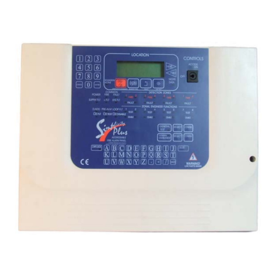
- Page 1 Simplicity Plus 64 OR 126 DEVICE CAPACITY, SINGLE LOOP ANALOGUE ADDRESABLE FIRE ALARM CONTROL PANEL INSTALLATION MANUAL...
-
Page 2: Table Of Contents
SIMPLICITY PLUS INSTALLATION MANUAL. Software Version :PANEL-R1578 & LOOP-R1062 CONTENTS 1.INTRODUCTION ..................................2 1.1 HANDLING THE PCBS ..............................2 1.2 USING THIS MANUAL ............................... 2 1.3 ABOUT THE SIMPLICITY FIRE ALARM PANEL & INTEGRAL PSE ................2 1.4 DESIGNING THE SYSTEM ............................... 2 1.5 EQUIPMENT GUARANTEE ............................... -
Page 3: Introduction
SIMPLICITY PLUS INSTALLATION MANUAL. Software Version :PANEL-R1578 & LOOP-R1062 1.INTRODUCTION THIS FIRE ALARM CONTROL PANEL IS CLASS 1 EQUIPMENT AND MUST BE EARTHED This equipment must be installed and maintained by a qualified and technically experienced person. 1.1 HANDLING THE PCBS If the PCBs are to be removed to ease fitting the enclosure and cables, care must be taken to avoid damage by static. -
Page 4: Simplicity Plus Overview
SIMPLICITY PLUS INSTALLATION MANUAL. Software Version :PANEL-R1578 & LOOP-R1062 2. SIMPLICITY PLUS OVERVIEW 2.1 PANEL DESCRIPTION & DESIGN CONCEPT The Simplicity Plus is a single-loop analogue addressable fire alarm control panel designed to EN54 part 2 & 4. It is available in two versions. Simplicity 64 allows 64 devices to be connected, and divided into 4 zones. Simplicity 126 allows 126 devices to be connected, and divided into 8 zones. -
Page 5: Improvements From V1 Cpu Card
SIMPLICITY PLUS INSTALLATION MANUAL. Software Version :PANEL-R1578 & LOOP-R1062 2.3 IMPROVEMENTS FROM V1 CPU CARD This version of the Simplicity panel has an upgraded CPU board to the previous version (Hence the name Simplicity Plus). The improvements include:- • Real time clock •... -
Page 6: Designing The System
SIMPLICITY PLUS INSTALLATION MANUAL. Software Version :PANEL-R1578 & LOOP-R1062 3. DESIGNING THE SYSTEM Designing a Simplicity System is a fairly straightforward matter. It just takes a bit of thought to zone allocation during the system design stage. 1. Decide on the zone allocation for the system. Each zone can have a maximum of 16 devices fitted. Consider the simplified 3-storey building below. -
Page 7: First Fix
SIMPLICITY PLUS INSTALLATION MANUAL. Software Version :PANEL-R1578 & LOOP-R1062 4. FIRST FIX 4.1 Mounting the Control Panel The control panel should be installed in accordance with the following recommendations:- • The panel should be close to the main entrance of the building, so that it can be viewed by any fire- fighting personnel entering the building. -
Page 8: Mounting The Fire Alarm Panel
SIMPLICITY PLUS INSTALLATION MANUAL. Software Version :PANEL-R1578 & LOOP-R1062 5. MOUNTING THE FIRE ALARM PANEL The Simplicity comes with many cable entry holes. If another entry hole is required, it is strongly recommended that the panels door be removed to avoid accidental damage. Also, the termination PCB should be removed and stored in a safe place. -
Page 9: Connecting Mains & Battery Power
SIMPLICITY PLUS INSTALLATION MANUAL. Software Version :PANEL-R1578 & LOOP-R1062 6 CONNECTING MAINS & BATTERY POWER 6.1 CONNECTING THE MAINS POWER INLET MAINS The panel should be connected to 220-240V AC by a 3A rated spur to the fuse box with 1mm to 2.5mm 3-core SUPPLY... -
Page 10: Addressable Loop Wiring
SIMPLICITY INSTALLATION MANUAL. Software:PANEL:R1107 & LOOP:R1062 7 ADDRESSABLE LOOP WIRING The Simplicity comes with one addressable loop. Addressable detectors, addressable call points, addressable loop powered sounders and several other interface units can be connected to these loops. A MAXIMUM OF 126 DEVICES CAN BE CONNECTED TO THE LOOP. -
Page 11: Specific Device Wiring Instructions
SIMPLICITY INSTALLATION MANUAL. Software:PANEL:R1107 & LOOP:R1062 7.1 SPECIFIC DEVICE WIRING INSTRUCTIONS Fyreye Common Base Fyreye Addressable Detector Relay Base FE-CB FEA-RB 80-050 80-080 LOOP - IN LOOP - OUT LOOP - IN LOOP - OUT RELAY OUTPUT LOOP + IN LOOP + OUT LOOP + IN LOOP + OUT... -
Page 12: List Of Compatible Equipment
SIMPLICITY INSTALLATION MANUAL. Software:PANEL:R1107 & LOOP:R1062 Zeta Input Unit Zeta Input Output Unit ZIOU 48-100 48-105 47K EOL 0.5W 47K EOL 0.5W LOOP - IN LOOP - OUT LOOP + IN LOOP + OUT LOOP - IN LOOP - OUT LOOP + IN LOOP + OUT Zeta Sounder Controller Circuit... -
Page 13: Maximum Loop Length Recommendations
SIMPLICITY INSTALLATION MANUAL. Software:PANEL:R1107 & LOOP:R1062 48-110 ZSCC Zeta Sounder Control Module 48-115 ZT-ZM Zeta Zone Monitor Unit (Loop Powered) 42-007 ZAMT Zeta Addressable Maxitone Sounder 42-060 ZAMDD Zeta Addressable Miditone Sounder 42-062 ZAMDF Zeta Addressable Miditone Sounder with LED Flasher 42-030 ZAST Zeta Addressable Securetone Sounder... -
Page 14: Address - Zone Table
SIMPLICITY INSTALLATION MANUAL. Software:PANEL:R1107 & LOOP:R1062 7.5 ADDRESS - ZONE TABLE On the Simplicity, each available address corresponds to a zone, with 1-16 being in zone 1, 17-32 being in zone 2, 33-48 in zone 3 etc. The table below shows the dip switch settings for each address, and the zone that address will be in. SW 4,3,2,1 OOOO OOO1 OO1O OO11 O1OO O1O1 O11O O111 1OOO 1OO1 1O1O 1O11 11OO 11O1 111O 1111 LOOP 1... -
Page 15: Dip Switch Address Settings - Full Table
SIMPLICITY INSTALLATION MANUAL. Software:PANEL:R1107 & LOOP:R1062 7.6 DIP SWITCH ADDRESS SETTINGS - FULL TABLE ADDRESS SWITCHES ADDRESS SWITCHES ADDRESS SWITCHES ADDRESS SWITCHES 1 2 3 4 5 6 7 1 2 3 4 5 6 7 1 2 3 4 5 6 7 1 2 3 4 5 6 7 n o t u s e d... -
Page 16: Sounders
SIMPLICITY INSTALLATION MANUAL. Software:PANEL:R1107 & LOOP:R1062 8 SOUNDERS 8.1 ADDRESSABLE SOUNDERS. On the Simplicity, addressable sounders (the ones that take a loop address) will always start quicker than associated sounders (ones that do not take an address. If sounder start time is an issue, choose an addressable type sounder. - Page 17 SIMPLICITY INSTALLATION MANUAL. Software:PANEL:R1107 & LOOP:R1062 Fault Output (FAULT): Gives 24V in the quiescent condition, and 0V in a fault condition. This ensures failsafe operation even in the event of total power loss. More than one relay can be connected to this output if required. Typical auxiliary output wiring FIT BACK-EMF DIODE ACROSS...
-
Page 18: Field Device Termination
SIMPLICITY INSTALLATION MANUAL. Software:PANEL:R1107 & LOOP:R1062 10. FIELD DEVICE TERMINATION 10.1 TERMINATING THE WIRING. INLET MAINS Brass Glands SUPPLY All cables entering the enclosure should have brass cable glands, which will ensure a good ground to the steel EMC cable grounding plate. CLA SS LOOP WIRING FLT REP... -
Page 19: Configuring The Simplicity Fire Alarm Panel
SIMPLICITY INSTALLATION MANUAL. Software:PANEL:R1107 & LOOP:R1062 12. CONFIGURING THE SIMPLICITY FIRE ALARM PANEL 12.1 CONFIGURING THE LOOPS Fire Alarm Panel 1 After the system has been installed, and the cabling To EN54 pt2 & pt4 checked and the addresses of each device set, connect System Normal the loop to the fire alarm panel and power up the system 15-01-2006 12:59... -
Page 20: Configuring The Sounder Bases
SIMPLICITY INSTALLATION MANUAL. Software:PANEL:R1107 & LOOP:R1062 12. When all devices have been entered, press Cancel to exit the message editing screen, and cancel again to exit the menu and to return to normal. The panel is now configured and ready for operation. 12.2 CONFIGURING THE SOUNDER BASES On the Simplicity, all detectors are treated as if they have a sounder base during the initial configuration. -
Page 21: Viewing Device Status
SIMPLICITY INSTALLATION MANUAL. Software:PANEL:R1107 & LOOP:R1062 12.5 VIEWING DEVICE STATUS On the Simplicity, all loop devices can be viewed from Configuration Menu 1, or viewed & edited from Configuration Menu 2. Optical Enter configuration menu 2 as described above, and select option 5 (Edit Device) Analog: Normal... -
Page 22: Using The Event Log
SIMPLICITY INSTALLATION MANUAL. Software:PANEL:R1107 & LOOP:R1062 If the device is an addressable sounder, or a detector with a sounder Optical base attached, the sounder can be started by pressing the Analog: Normal TEST button. The Outline sounder Symbol turns solid to show that the Sounder is active. -
Page 23: Disablement
SIMPLICITY INSTALLATION MANUAL. Software:PANEL:R1107 & LOOP:R1062 13. DISABLEMENT On the Simplicity, there are 2 disablement options. A whole zone of detectors can be disabled, or an individual point can be disabled. Both types of disablement can be used at the same time if required. 13.1 ZONE DISABLEMENT To aid commissioning and assist routine maintenance checks, any of the zones or the loop sounders can be disabled. -
Page 24: Viewing Disablements
SIMPLICITY INSTALLATION MANUAL. Software:PANEL:R1107 & LOOP:R1062 13.4 VIEWING DISABLEMENTS There are two ways to check for disablements: from the Disablement screen, or from the device status screen. To view from the disablement screen, press disable, then press select to scroll through all the zones & sounders. If there are no disablements, the screen will show Zone Disablement Zone... -
Page 25: Test Mode
SIMPLICITY INSTALLATION MANUAL. Software:PANEL:R1107 & LOOP:R1062 14. TEST MODE 14.1 WHY USE TEST MODE To aid commissioning and assist routine maintenance check, a non-latching ‘one man test’ facility is available. When a detector or manual call point is triggered on any zone in Test, the Alarm sounders operate for approximately eight seconds on and four seconds off. -
Page 26: General Fault Finding
SIMPLICITY INSTALLATION MANUAL. Software:PANEL:R1107 & LOOP:R1062 15. GENERAL FAULT FINDING On the Simplicity panel, Faults are divided into 2 types, “Faults” and “Device Faults”. Device Faults are any fault associated with a particular address on the loop. Faults is everything else, EG sounder circuits, power supply etc. -
Page 27: Supply Faults
SIMPLICITY INSTALLATION MANUAL. Software:PANEL:R1107 & LOOP:R1062 15.4 SUPPLY FAULTS FAULT 1 of 1 BATTERY FAULT Loss of Battery power – Remedy Check battery fuse FS2. Battery Fault Check that battery connections are secure. CHARGER FAULT Loss of Mains power – Remedy FAULT Check mains fuse (Conn 6). -
Page 28: Sounder Faults
SIMPLICITY INSTALLATION MANUAL. Software:PANEL:R1107 & LOOP:R1062 15.9 SOUNDER FAULTS On the Simplicity there are only loop controlled sounders fitted. Fault-finding these is similar faultfinding zone faults. Sounder circuit controllers(ZSCC). Check :- Check that the correct END of Line resistor os fitted. (47K – Yellow, purple, orange, gold) Check that the sounder fuses is OK (FS1, –... -
Page 29: Standby Battery Requirements
SIMPLICITY INSTALLATION MANUAL. Software:PANEL:R1107 & LOOP:R1062 16. STANDBY BATTERY REQUIREMENTS The Following Table shows the Quiescent, Fault & alarm currents of the main parts of a Simplicity Fire Alarm System Device Product Code (mA) (mA) (mA) Loop System SIMPLICITY 64 Fire Alarm Panel SP-64 SIMPLICITY 126 Fire Alarm Panel SP-126... -
Page 30: Standby Battery Calculation
SIMPLICITY INSTALLATION MANUAL. Software:PANEL:R1107 & LOOP:R1062 16.1 STANDBY BATTERY CALCULATION In order to calculate the standby battery size required, the following formula can be used:- Battery Size (Standby time in Amp Hours) = 1.25 x [(T ) + (T x (I Where: = Maximum time in hours required for the alarm [½... -
Page 31: Pcb Termination Connections
SIMPLICITY INSTALLATION MANUAL. Software:PANEL:R1107 & LOOP:R1062 17. PCB TERMINATION CONNECTIONS. CLASS LOOP WIRING FLT REP CHANGE 1 2 3 4 5 6 CONN29 FS1 FS2 7 8 9 LIVE NEUT- EARTH 17.1 CONNECTIONS Connection No Description LOOP 1A +&- Connect to loop 1 side A LOOP 1B +&- Connect to loop 1 side B FIRE REPEAT OUTPUT... -
Page 32: Panel Specifications
SIMPLICITY INSTALLATION MANUAL. Software:PANEL:R1107 & LOOP:R1062 17. PANEL SPECIFICATIONS 17.1 ENCLOSURE SPECIFICATIONS DESCRIPTION VALUE ENCLOSURE SIZE 355 x 275 x 100 mm TOP CABLE ENTRIES 12 x 19mm DIA GROMMETED ENTRIES BOTTOM CABLE ENTRIES 2 x 19mm KNOCKOUT ENTRIES REAR CABLE ENTRIES 2 SNAP OUTS, 60 x 20mm 17.2 ELECTRICAL SPECIFICATIONS ELECTRICAL DESCRIPTION...
Need help?
Do you have a question about the SP-64,126 and is the answer not in the manual?
Questions and answers