Zeta Premier M+ Installation Manual
8-24 zone conventional fire alarm panel
Hide thumbs
Also See for Premier M+:
- User manual, maintenance manual & log book (24 pages) ,
- Log book & certificates (17 pages) ,
- User manual & maintenance manual (14 pages)

Subscribe to Our Youtube Channel
Related Manuals for Zeta Premier M+


Summary of Contents for Zeta Premier M+
- Page 1 PREMIER M PLUS INSTALLATION MANUAL 8-24 ZONE CONVENTIONAL FIRE ALARM PANEL INSTALLATION MANUAL Approved Document No: GLT.MAN-111 Issue : 2.8 Author: NJ Date: 23/07/2012...
-
Page 2: Premier M Plus Overview
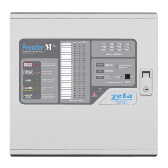
PREMIER M PLUS INSTALLATION MANUAL PREMIER M PLUS OVERVIEW The Premier M plus is a medium size conventional panel from Zeta Alarm Systems. Its Features include:- Designed to EN54 Parts 2 & 4. It is available in 8 ,16 or 24 zones sizes. ... -
Page 3: Table Of Contents
PREMIER M PLUS INSTALLATION MANUAL Contents PREMIER M PLUS OVERVIEW ...................................1 1.SAFETY INFORMATION ..................................3 1.1 INSTALLATION INFORMATION ..............................3 1.2 BATTERY INFORMATION ................................3 1.3 PRODUCT DISPOSAL AT THE END OF ITS WORKING LIFE ......................3 2. PRODUCT DESIGN INFORMATION ................................4 2.1 FIRE ALARM CONTROL SECTION ..............................4 2.2 POWER SUPPLY SECTION ................................4 2.3 ENVIRONMENTAL ..................................4 2.4 DESIGNING THE SYSTEM ................................4... -
Page 4: Safety Information
PREMIER M PLUS INSTALLATION MANUAL 1.SAFETY INFORMATION WARNING: Read this section completely before commencing installation. 1.1 INSTALLATION INFORMATION THIS FIRE ALARM CONTROL PANEL IS CLASS 1 EQUIPMENT AND MUST BE EARTHED This equipment must be installed and maintained by a qualified and technically experienced person. This C.I.E. -
Page 5: Product Design Information
PREMIER M PLUS INSTALLATION MANUAL 2. PRODUCT DESIGN INFORMATION 2.1 FIRE ALARM CONTROL SECTION The Premier M Plus Fire Alarm Control and Indicating Equipment (CIE) Has been designed to EN54-2:1998 A1 + A2 - Fire Detection & Fire Alarm Systems – Control & Indicating Equipment. As well as meeting the requirements of EN54-2:1998 A1 + A2, the Premier M Plus also has the following options with requirements:- Clause 7.8 Output to fire alarm devices... -
Page 6: First Fix
PREMIER M PLUS INSTALLATION MANUAL 3. FIRST FIX All wiring must be installed to meet BS5839-1:2002+A2:2008 and BS 7671 (Wiring Regs) standards. Other National standards of fire alarm system installation should be adhered to where applicable. 3.1 RECOMMENDED CABLE TYPES AND THEIR LIMITATIONS Screened cables should be used throughout the installation to help shield the Panel from outside interference and ensure EMC compatibility. -
Page 7: Sounder Circuit Wiring Diagram
PREMIER M PLUS INSTALLATION MANUAL Old Manual call points, which just cause a short circuit, are not directly compatible, as they would cause a short circuit fault. Fitting a 470R resistor in line with the call point will allow it to work. - Page 8 PREMIER M PLUS INSTALLATION MANUAL The fire relay can be used to connect to various devices which are activated on a fire alarm. Eg. Auto dialler, magnetic door release (24V), sprinkler system etc. 3.5.2 Fault Output (FAULT): Voltage free changeover contacts. This Output is energised in the quiescent condition. In a fault condition, the output relay turns off, to ensure fail-safe operation even in the event of total power loss.
-
Page 9: Mounting The Fire Alarm Panel
PREMIER M PLUS INSTALLATION MANUAL 4. MOUNTING THE FIRE ALARM PANEL When working alone, it is recommended that the panel door be removed to avoid accidental damage. Also, the termination PCB could be removed and stored in a safe place while fixing the back box to the wall. 4.1 PLANNING CABLE ENTRY Fig.2 below shows the location of the cable entries to facilitate planning of wiring (home runs) to be brought to the panel. -
Page 10: Connecting Mains & Battery Power
PREMIER M PLUS INSTALLATION MANUAL 5. CONNECTING MAINS & BATTERY POWER 5.1 CONNECTING THE MAINS POWER The panel should be connected to 230V AC by a 5A rated spur to the fuse box with 1mm2 to 2.5mm2 3-core cable. Nothing else should be connected to this supply. This cable should be fire resistant. -
Page 11: Field Device Termination
PREMIER M PLUS INSTALLATION MANUAL 6. FIELD DEVICE TERMINATION 6.1 TERMINATING THE DETECTION AND ALARM (SOUNDER) CIRCUITS. All cables entering the enclosure should have cable glands fitted, and their earth screens connected to the Earth bar as shown. This will ensure a good EMC performance. The Detection and Sounder circuits should be connected to the appropriate connector block on the Termination PCB as shown in Figure 6 below. -
Page 12: Configuring The Panel
PREMIER M PLUS INSTALLATION MANUAL 7. CONFIGURING THE PANEL 7.1 SOUNDER ACTIVATION DELAY 7.1.1 Deciding to use a Delay A delay of up to nine minutes from the Fire Alarm Panel being triggered, to its Alarm sounder outputs being activated, can be programmed into the panel by the Engineer. -
Page 13: To Programme Zone (Or Sounders) As Disabled
PREMIER M PLUS INSTALLATION MANUAL When a zone (or sounder circuit) is disabled, the panel will not respond to any fault or fire signals it receives from that zone. This might be used if the system requires routine maintenance, and the customer needs the system to continue running, but doesn’t want spurious false alarms. -
Page 14: Zone Test
PREMIER M PLUS INSTALLATION MANUAL 9. ZONE TEST 9.1 WHY USE ZONE TEST To aid commissioning and assist routine maintenance checks, a non-latching test mode facility is available. When a detector or manual call point is triggered on any zone in Test, the Alarm sounders operate for approximately four seconds on and four seconds off. -
Page 15: General Fault Finding
PREMIER M PLUS INSTALLATION MANUAL 10. GENERAL FAULT FINDING 10.1 ZONE FAULTS The Zone Faults are non-latching faults. That is, if the fault has been cleared, the panel will automatically reset itself. Open circuit faults will be indicated by zone(s) fault LED being lit steady, the internal Fault Buzzer will sound and the General Fault LED will be lit. -
Page 16: Earth Faults
PREMIER M PLUS INSTALLATION MANUAL resistance is greater than 0.9 ohm. These batteries would then need to be replaced. 10.4 EARTH FAULTS An EARTH fault indicates that something is shorting to earth (usually through the cable screen). Disconnect the earth screens one at a time to determine the problem line. -
Page 17: Standby Battery Calculation
PREMIER M PLUS INSTALLATION MANUAL 11. STANDBY BATTERY CALCULATION In order to calculate the standby battery size required, the following formula can be used:- Battery Size (Standby time in Amp Hours) = 1.25 x [(T ) + (T x (I Where: = Maximum time in hours required for the alarm [½... -
Page 18: Pcb Termination Connections
PREMIER M PLUS INSTALLATION MANUAL 12. PCB TERMINATION CONNECTIONS 12.1 CONTROL PANEL CONNECTIONS 12.2 CONTROL PANEL CONNECTIONS CONNECTION NO DESCRIPTION ZONE 1 to 8 +&- Connect to Detection Zones 1 to 8 ZONE 9 to 16 +&- Connect to Detection Zones 9 to 16 ZONE 17 to 24 +&- Connect to Detection Zones 17 to 24 Power Supply (Earth, 0V, 28V) -
Page 19: Power Supply Pcb
PREMIER M PLUS INSTALLATION MANUAL Sounder circuit 2 400mA time delay 5 x 20mm glass AUX Supply 250mA time delay 5 x 20mm glass Sounder circuit 3 400mA time delay 5 x 20mm glass Sounder circuit 4 400mA time delay 5 x 20mm glass 28V Supply Fuse 6A time delay 5 x 20mm glass 12.4 POWER SUPPLY PCB... -
Page 20: Power Supply Connections
PREMIER M PLUS INSTALLATION MANUAL 12.5 POWER SUPPLY CONNECTIONS CONNECTION NO DESCRIPTION EXT PSU IP External Power input from Switch Mode cage FAULT OP Volt free fault relay, normally energised A-FUSE Fuse for the first 24V output 24V A Connection for the first 24 V output 24V B Connection for the second 24 V output B-FUSE... -
Page 21: Panel Specifications
PREMIER M PLUS INSTALLATION MANUAL 13. PANEL SPECIFICATIONS 13.1 ENCLOSURE SPECIFICATIONS DESCRIPTION VALUE ENCLOSURE SIZE 485 X 478 X 125mm TOP CABLE ENTRIES 20 X 19mm DIA GROMMETED ENTRIES BOTTOM CABLE ENTRIES 6 X 19mm DIA GROMMETED ENTRIES REAR CABLE ENTRIES 13.2 ELECTRICAL SPECIFICATIONS ELECTRICAL DESCRIPTION VALUE... - Page 22 PREMIER M PLUS INSTALLATION MANUAL 0359 Zeta Alarm Systems by GLT Exports Ltd, 72-78 Morfa Road, Swansea SA1 2EN 0359-CPD-0143 EN54-2:1997+A1:2002 + A2: 2006 EN54-4:1997+A1:2002 + A2: 2006 Control and indicating equipment for fire detection and fire alarm systems for buildings PMP8, PMP16, PMP24 Provided options: Output to fire alarm devices...
Need help?
Do you have a question about the Premier M+ and is the answer not in the manual?
Questions and answers