Sign In
Upload
Manuals
Brands
Zeta Manuals
Fire Alarms
Simplicity Plus
Zeta Simplicity Plus Manuals
Manuals and User Guides for Zeta Simplicity Plus. We have
3
Zeta Simplicity Plus manuals available for free PDF download: Installation Manual, User Manual, Maintenance Manual & Log Book
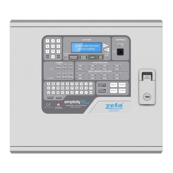
Zeta Simplicity Plus Installation Manual (50 pages)
ONE OR TWO LOOP ANALOGUE ADDRESSABLE FIRE ALARM CONTROL PANEL
Brand:
Zeta
| Category:
Fire Alarms
| Size: 4 MB
Table of Contents
Table of Contents
2
1 Safety Information
4
Installation Information
4
Safety Precautions During Normal Operation of Panel
4
Battery Information
4
Product Disposal at the End of Its Working Life
4
2 Product Design Information
5
Fire Alarm Control Section
5
Power Supply Section
5
Environmental
5
3 Introduction to the Simplicity Panel
6
Simplicity Panel History
6
Panel Description & Design Concept
7
Advantages of an Addressable Fire Alarm System
7
4 Using this Manual
8
Equipment Guarantee
8
5 Designing a System
9
Designing a Simplicity System
9
6 Installing the System
10
Considerations before Installation
10
Mounting the Control Panel
10
Recommended Cable Types and Their Limitations
10
Mains Wiring Recommendations
10
First Fix
11
Mounting the Fire Alarm Panel
11
Fixing the Back Box to the Wall
11
Planning Cable Entry
11
Connecting the Mains Power
12
Connecting the Batteries
13
7 Addressable Loop Wiring
14
Specific Device Wiring Instructions
15
CP3/AD Manual Call Point
15
MKII Detectors (All Types)
15
ZAI - MI Input Module
16
ZAIO - MI Input/Output Module
16
ZASC - MI Sounder Control Module
16
ZAZM - MI Conventional Zone Module
17
Xtratone Sounder/Sounder Flasher
17
Sandwich Sounder
17
Remote LED Indicator
17
Isolator Base
18
Maximum Loop Length Recommendations
18
Setting the Device Address (Detectors, Call Points & Sounders)
18
Address - Zone Table
19
8 Sounders
20
Addressable Sounders
20
Sandwich Sounder Bases - Detector Triggered
20
Sandwich Sounder Bases - Addressd Mode
20
Addressable Sounder Circuit Controller
20
Comparison of Sounder Types
20
Sounder Start & Stop Times
21
9 Auxiliary Inputs & Outputs
22
Auxiliary Input Wiring Examples
22
Auxiliary Output Wiring
22
10 Field Device Termination
23
Terminating the Wiring
23
11 Other Connections
24
Repeater Connection
24
Serial Printer Connection
24
12 Configuring the Simplicity Fire Alarm Panel
25
Configuring the Loops
25
From a Blank Simplicity Panel
25
From a Previously Configured Panel
25
Reduced Loop Simplicity Panels
25
Verifying the Loop Configuration
25
Labelling the Loop Devices
26
Configuring Associated Sounders
26
Setting Time and Date
26
Setting a Custom Banner
26
Changing a Zone Boundary
27
Changing the Alarm Response - Sounders
27
Changing Detector Alarm Response
27
Changing Mcp Alarm Response
27
Zonal Sounder to Common Sounder Delay
27
Associated Sounder Base Settings
28
Changing the Alarm Response - I/O Units
28
Types of I/O Unit Operation
28
Setting Default I/O Unit Operation
28
Setting Individual I/O Unit Output Operation
29
Setting Individual I/O Unit Input Operation
29
Setting the Lcd Language
30
Software Versions
30
Protocol
31
13 Alarm Verification
32
How Alarm Verification Works
32
14 Restoring the Panels Default Settings
33
15 Viewing Panel Information
34
Menu Structure
34
Viewing Device Status
35
Locating a Device
35
Using the Event Log
36
16 The Fire Alarm Condition
37
Viewing a Fire Alarm Event
37
Viewing Faults During a Fire Alarm Condition
37
Viewing Zone Disablements During a Fire Alarm Condition
37
Viewing Device Disablements During a Fire Alarm Condition
37
17 Disablement
38
Zone Disablement
38
To Programme Zone (or Sounders) as Disabled
38
Device Disablement
38
Viewing Disablements
39
Viewing Disabled Zones
39
Viewing Disabled Devices
39
18 Test Mode
40
Why Use Test Mode
40
To Programme Zone in Test Mode
40
19 General Fault Finding
41
Common Fault
41
Loop Contents Fault Finding
41
Zone Faults
41
Supply Faults
41
Earth Faults
42
Double Address
42
System Fault
42
Pre-Alarm
42
Sounder Faults
42
Loop Wiring Faults
42
20 Standby Battery Requirements
44
Standby Battery Calculation
45
21 Pcb Termination Connections
46
Simplicity Plus Cie Termination Pcb
46
Connections
46
Simplicity Plus Power Supply Pcb
47
Simplicity Plus Power Supply Connections
47
Simplicity Plus Power Supply Fuses
47
22 Specifications
48
Enclosure Specifications
48
Electrical Specifications
48
Advertisement
Zeta Simplicity Plus Installation Manual (32 pages)
64 OR 126 DEVICE CAPACITY, SINGLE LOOP ANALOGUE ADDRESABLE FIRE ALARM CONTROL PANEL
Brand:
Zeta
| Category:
Fire Alarms
| Size: 0 MB
Table of Contents
Table of Contents
2
1 Introduction
3
Handling the Pcbs
3
Using this Manual
3
About the Simplicity Fire Alarm Panel & Integral Pse
3
Designing the System
3
Equipment Guarantee
3
2 Simplicity Plus Overview
4
Panel Description & Design Concept
4
Advantages of an Addressable Fire Alarm System
4
Improvements from V1 Cpu Card
5
3 Designing the System
6
4 First Fix
7
Mounting the Control Panel
7
Recommended Cable Types and Their Limitations
7
Mains Wiring Recommendations
7
5 Mounting the Fire Alarm Panel
8
Planning Cable Entry
8
Fixing the Back Box to the Wall
8
Connecting Mains & Battery Power
9
Connecting the Mains Power
9
Connecting the Batteries
9
Addressable Loop Wiring
10
Specific Device Wiring Instructions
11
List of Compatible Equipment
12
Maximum Loop Length Recommendations
13
Setting the Device Address (Detectors, Call Points & Sounders)
13
Address - Zone Table
14
Dip Switch Address Settings - Full Table
15
Sounders
16
Addressable Sounders
16
Associated Sounder Bases
16
Supported Sounder Types & Their Applications
16
9 Auxiliary Inputs & Outputs
16
Auxiliary Input Wiring Examples
16
10 Field Device Termination
18
Terminating the Wiring
18
Other Connections
18
Repeater Connection
18
Serial Printer Connection
18
12 Configuring the Simplicity Fire Alarm Panel
19
Configuring the Loops
19
Configuring the Sounder Bases
20
Setting Time and Date
20
Setting a Custom Banner
20
Viewing Device Status
21
Locate or Verify a Device
21
Using the Event Log
22
Checking Software Version
22
13 Disablement
23
Zone Disablement
23
To Programme Zone (or Sounders) as Disabled
23
Point Disablement
23
Viewing Disablements
24
14 Test Mode
25
Why Use Test Mode
25
To Programme Zone in Test Mode
25
To Program Sounder Circuits in Test Mode
25
15 General Fault Finding
26
Common Fault
26
Loop Contents Fault Finding
26
Zone Faults
26
Supply Faults
27
Earth Faults
27
Double Address
27
System Fault
27
Pre-Alarm
27
Sounder Faults
28
Loop Wiring Faults
28
16 Standby Battery Requirements
29
Standby Battery Calculation
30
17 Pcb Termination Connections
31
Connections
31
Fuses
31
Panel Specifications
32
Enclosure Specifications
32
Electrical Specifications
32
Zeta Simplicity Plus User Manual, Maintenance Manual & Log Book (23 pages)
64 OR 126 DEVICE CAPACITY, SINGLE LOOP ANALOGUE ADDRESABLE FIRE ALARM CONTROL PANEL
Brand:
Zeta
| Category:
Fire Alarms
| Size: 0 MB
Table of Contents
Log Book
1
Table of Contents
2
What to Do if the Fire Alarm Panel Shows an Alarm (Red LED)
3
What to Do if the Fire Alarm Panel Shows a Fault (Yellow LED)
3
1 Fire Alarm Control Panel Safety Issues
4
2 The Purpose of a Fire Alarm System
4
3 User Responsibilities & Maintainence of the Fire Alarm System, Including the Facp & Its Integral Pse
5
4 Panel Indications & Controls
6
Access Levels
7
Checking the Panels Indication Leds
7
What the Leds Mean
7
5 The Fire Condition
8
How the Simplicity Indicates an Alarm
8
To Turn off the Alarm Sounders
8
A Second Alarm Signal from a New Detection Zone
8
Turning on the Alarm Sounders from the Facp (I.e. to Evacuate the Building)
8
Resetting the Panel
8
6 The Fault Condition
9
Different Types of Fault
9
What to Do if a Fault Condition Occurs
10
Other Led Indications
10
7 Disablements
11
Reasons for Disabling Certain Parts of a Fire Alarm System
11
To Disable a Zone And/Or External Sounders
11
To Enable a Zone And/Or External Sounders
11
8 System Description
12
Fire Alarm System Summary
12
Detailed Loop Contents
13
9 Fire Alarm Log Book
14
Maintenance Work
15
False Alarms
16
All Events Other than Maintenance Work or False Alarms
17
Commissioning the System, Including P.s.e
18
Design, Installation & Commissioning Certificates
18
Design Certificate
19
Installation Certificate
21
Commissioning Certificate
22
Acceptance Certificate
23
Advertisement
Advertisement
Related Products
Zeta SP-64
Zeta SNAP
Zeta SP-126/M
Zeta SmartConnect
Zeta Smart Connect Multi-loop
Zeta SmartConnect SMART1
Zeta SmartConnect SMART1/M
Zeta 126
Zeta CP-CV
Zeta CP-KY
Zeta Categories
Fire Alarms
Control Panel
Smoke Alarm
Security System
Marine Equipment
More Zeta Manuals
Login
Sign In
OR
Sign in with Facebook
Sign in with Google
Upload manual
Upload from disk
Upload from URL