Table of Contents
Advertisement
Quick Links
Advertisement
Table of Contents

Related Manuals for Fujitsu DL6400Pro


Summary of Contents for Fujitsu DL6400Pro
- Page 1 USER’S MANUAL...
- Page 2 Federal Communications Commission Radio Frequency Interference Statement for United States Users Notice: This equipment has been tested and found to comply with the limits for a Class B digital device, pursuant to Part 15 of FCC Rules. These limits are designed to provide reasonable protection against harmful interference in a residential installation.
- Page 3 Notice to Canadian Users This Class B digital apparatus meets all requirements of the Canadian Interference-Causing Equipment Regulations. Cet appareil numérique de la Classe B respecte toutes les exigences du Règlement sur le matériel brouilleur du Canada. Notice to German Users Bescheinigung des Herstellers/Importeurs Hiermit wird bescheinigt, daß...
-
Page 4: Manufacturer's Declaration Of Conformity
Manufacturer's Declaration of Conformity According to Electromagnetic Compatibility Directive 89/336/EEC and Low Voltage Directive 73/23/EEC, Annex IIIB. FUJITSU ISOTEC LIMITED, 135 Higashinozaki Hobara-machi Date-gun, Fukushima, 960-0695, Japan Declares, in sole responsibility, that the following products Product Type : DOT MATRIX PRINTER... -
Page 5: Trademark Acknowledgment
Trademark Acknowledgment FUJITSU is a registered trademark and Fujitsu Creative Faces is a trademark of Fujitsu Limited. Centronics is a trademark of Centronics Data Computer Corporation. IBM PC and IBM Proprinter XL24E are trademarks of International Business Machines Corporation. - Page 6 The printer has an LED or LCD control panel. This manual describes the operation of the printer with the LED control panel. For the operation of the printer with the LCD control panel, see Appendix E. As an E ® Partner, FUJITSU LIMITED has determined...
- Page 7 User’s Manual...
-
Page 8: Table Of Contents
Printing on Cut Sheets ... 4-10 Returning to Continuous Forms ... 4-12 Chapter 5 Operating the Printer ... 5-1 Using the Control Panel ... 5-1 Turning Printer Power On and Off ... 5-8 User’s Manual FRONT ... 1-3 BACK ... 1-3 INSIDE ... 1-4 SIDES (left side shown) ... - Page 9 Contents Test Printing ... 5-8 Demonstration Pattern Printing ... 5-11 Sensor Detection ... 5-13 Chapter 6 Clearing Paper Jams... 6-1 Continuous Forms (Front) ... 6-1 Continuous Forms (Rear) ... 6-4 Cut Sheets ... 6-4 Chapter 7 Paper Specifications ... 7-1 Continuous Forms ...
- Page 10 Chapter 12 Specifications... 12-1 Appendix A Consumables and Options ... A-1 Appendix B Command Sets ... B-1 Fujitsu DPL24C PLUS ... B-2 IBM Proprinter XL24E Emulation ... B-18 EPSON ESC/P2 Emulation ... B-23 Appendix C Interface Information ...C-1 Parallel Interface ...C-1 Data Transmission Timing ...C-6...
- Page 11 Contents Power-on Special Functions ...E-22 Messages ...E-23 Index ...IN-1 Fujitsu Offices ...Inside back cover Saving changed options ...E-17 Printing the self-test ...E-20 Correcting vertical character displacement ...E-21 Status messages ...E-23 Error messages ...E-27 Messages indicating user-correctable problems ...E-27 Messages indicating fatal errors ...E-33...
-
Page 12: Chapter 1 Introduction
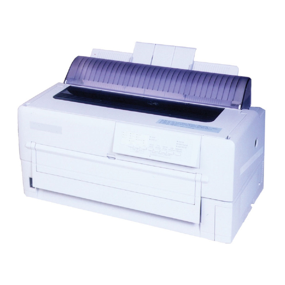
CHAPTER Introduction The DL6400 Pro/DL6600 Pro is a 24-dot impact printer used for Overview image and graphics reproduction. Figure 1-1 shows the printer. Figure 1–1 DL6400 Pro/DL6600 Pro printer User’s Manual INTRODUCTION... -
Page 13: Package Contents
Package Contents Check that the printer package contains the items shown in Figure 1-2. Package For missing items, contact the Fujitsu sales department. Contents Printer Ribbon cassette Paper guides Figure 1–2 Components Platen knob Maximum length 3 meters Power cord Paper guide User’s manual... -
Page 14: Parts And Functions
Figures 1-3 and 1-4 show the printer parts. Parts and Functions The numbers in the figures correspond to the parts listed in Table 1-1. FRONT q Top cover !1 Front cover !0 Power switch o Front cut-sheet guide i Front tray... -
Page 15: Inside
Parts and Functions INSIDE !8 Print head !9 Platen !7 Ribbon cassette @0 Paper thickness lever SIDES (left side shown) @1 Jam removal lever @2 Lock lever @3 Tractor @4 Center guide Figure 1–4 Parts (2) User’s Manual... - Page 16 User’s Manual Function Protects the print head and other internal printer components. Guides paper into the printer. Set based on the cut-sheet or continuous forms width. Set down for continuous forms and up for cut sheets. Cuts continuous forms. Turned to feed paper manually.
- Page 17 Lock lever Tractor Center guide Function Contains the printing ribbon. If characters do not print clearly, replace the ribbon or cassette. A Fujitsu ribbon is recommended. Performs actual printing. Controls and feeds paper. Used to manually adjust paper thickness. Turned down to allow jammed paper to be removed more easily.
-
Page 18: Chapter 2 Setting Up The Printer
CHAPTER Setting Up the Printer The printer is shipped with a stopper and cushion inside that prevent Removing the vibration and other movement that could cause damage during Stopper and shipment. Cushion 1. Open the top cover and lift out the stopper as shown by the arrow in the figure. -
Page 19: Installing The Paper Guide
Insert the paper guide, at an angle, into the left and right guide grooves Installing the on the back cover and slide it back into place. Paper Guide Back cover Guide groove Paper guide Back of printer Paper exit User’s Manual... -
Page 20: Installing The Platen Knob
Insert the platen knob and align it with the gear teeth. Installing the Platen Knob User’s Manual Installing the Platen Knob SETTING UP THE PRINTER Platen shaft Platen knob... -
Page 21: Connecting The Power Cord
1. Turn off printer power ( ). Connecting the Power Cord 2. Connect the power cord to the connector on the back of the printer, at the right side. 3. Plug the power cord into an outlet. Power cord connector Power cord User’s Manual... -
Page 22: Connecting The Interface Cable
Interface Cable 2. Connect the interface cable to the connector at the back of the printer, on the left side. Make sure the orientation is correct. Press the left and right lock pins down to secure the cable. 3. Connect the cable to the computer. For more information, refer to the computer user's manual. - Page 23 User’s Manual...
-
Page 24: Chapter 3 Installing The Ribbon Cassette
Notice: A Fujitsu ribbon cassette is recommended. Other cassettes may cause operating problems or damage the print head. Fujitsu takes no responsibility for print head faults caused by such cassettes. -
Page 25: Preparing The Ribbon Cassette
3. Turn the knob clockwise to check that the ribbon moves smoothly. Remove the protective tabs Notice: Adjust the paper thickness lever on the printer appropriately for the forms used. Otherwise, the ribbon may come loose or paper may be smeared by ink from the ribbon. -
Page 26: Installing The Ribbon Cassette
1. Turn off printer power ( ). Installing the Ribbon Cassette 2. Open the top cover of the printer and move the paper thickness lever to D. Print head 3. Manually move the print head to the left side so that it is one third of the printer width from the left side. - Page 27 Installing the Ribbon Cassette 4. Align the pins on both ends of the ribbon cassette with the guide grooves inside the printer. Then press the ribbon cassette down to install it. Ribbon cassette 5. Hook the ribbon over the ribbon guide.
-
Page 28: Removing The Ribbon Cassette
1. Turn off printer power ( ). Removing the Ribbon Cassette 2. Open the top cover of the printer. 3. Remove the ribbon from the ribbon guide. 4. Pull the ribbon cassette towards you to unlock it and remove the cassette from the printer. -
Page 29: Replacing The Subcassette
Subcassette Notice: A Fujitsu ribbon cassette is recommended. Other cassettes may cause operating problems or damage the print head. Fujitsu takes no responsibility for print head faults caused by such cassettes. Replace the cassette carefully to avoid getting ink on your hands. - Page 30 6. When loading the new subcassette into the ribbon cassette, check that the orientation of the new subcassette is correct. After loading remove the paper tape. 7. Holding the subcassette casing, slide the bottom of the casing to the right to remove it. Feed roller A 8.
- Page 31 Replacing the Subcassette 10. Press lock tabs B in the direction of the arrows to return feed roller A to its original position. Then close the cassette lid. Turn the knob clockwise to check that the ribbon moves smoothly. 11. Check off the subcassette replacement column on the cassette label. 12.
-
Page 32: Chapter 4 Loading Paper
CHAPTER Loading Paper 1. Turn on the printer power switch ( | ). Loading Continuous 2. Press the PAPER PATH button on the control panel to select Forms (Front) FRONT TRACTOR. The FRONT TRACTOR lamp lights. 3. Move the paper guide back as indicated by the arrow in the figure. - Page 33 Loading Continuous Forms (Front) 5. Raise the cut-sheet tray. 6. Turn the lock levers of the left and right tractors in the direction in- dicated by the arrow to unlock them. Lock lever 7. Move the left tractor to the reference point on the lower cover. Then press the lock lever in the direction of the arrow in the figure below to lock it.
- Page 34 10. Open the paper holders of the left and right tractors. Align the forms feed holes with the tractor pins and close the paper holders. 11. Move the right tractor to add slight tension to the paper. Then press the lock lever in the direction of the arrow to lock it. User’s Manual Loading Continuous Forms (Front) Tractor pins...
- Page 35 Loading Continuous Forms (Front) 12. Lower the cut-sheet tray. 13. Close the front cover of the printer. Front cover Cut-sheet tray User’s Manual...
- Page 36 16. Adjust the position of the print line To adjust the print line to the position that you require, open the top cover of the printer and align the red mark of the indicator with the position you require the bottoms of characters to be.
-
Page 37: Loading Continuous Forms (Rear)
1. Press the TEAR OFF button on the control panel. The continuous forms are then automatically loaded to where they are to be cut. For the operation of the printer with the LCD control panel, see Appendix E. 2. Open the noise-proof cover. -
Page 38: Loading Cut Sheets
Important: Continuous forms cannot be cut where there are no perforations. Paper cutter 1. Turn on printer power ( | ). Loading Cut Sheets 2. Press the PAPER PATH button on the control panel to select FRICTION (friction feed). The FRICTION lamp lights. - Page 39 Loading Cut Sheets 4. Open the front tray. Power switch on ( | ) 5. Align the cut-sheet guide with the reference point. Cut-sheet guide Reference point Front tray Front guide Paper guide User’s Manual...
- Page 40 6. Insert paper while aligning its left edge with the cut-sheet guide. Cut-sheet guide 7. Press the LOAD button (or LOAD/UNLOAD button). The paper is then loaded to the print start position. Notice: If paper is not loaded correctly, a paper feed error or skewed loading may occur.
-
Page 41: Printing On Cut Sheets
Printing on Cut Sheets You can print on cut sheets without removing continuous forms from Printing on Cut the tractor section. Sheets 1. Press the PAPER PATH button on the control panel to select FRICTION (friction feed). The FRICTION lamp lights. Important: 1. - Page 42 Printing on Cut Sheets 2. Load cut sheets as explained in “Loading Cut Sheets” on page 4-7 without removing the continuous forms. LOADING Cut sheet PAPER Continuous forms User’s Manual 4-11...
-
Page 43: Returning To Continuous Forms
Returning to Continuous Forms After printing on cut sheets with continuous forms loaded, you can Returning to easily return to printing continuous forms. Continuous Forms 1. Remove cut sheets, if any. 2. Tip back the paper guide. Front tray 3. Close the front tray. 4. -
Page 44: Chapter 5 Operating The Printer
1. Layout Figure 5-1 shows the LED type control panel layout. Figure 5–1 Control panel layout (LED type) 2. Lamps Control panel lamps indicate the printer status. Table 5-1 lists the lamp functions. Table 5–1 Lamp functions (LED type) Lamp... - Page 45 Using the Control Panel Table 5–1 Lamp functions (LED type) (Continued) Lamp FRICTION FRONT TRACTOR REAR TRACTOR LOCKED COUR10 PRESTG12 COMPRESS17 Bold PS Time PS N. Sans PS DRAFT10 DRAFT12 MENU FONT Function Lights when cut sheets can be used. Switched by pressing the PAPER PATH button.
- Page 46 Tear off mode is valid for continuous forms only. When this button is pressed, the printer performs centering, and the ONLINE lamp blinks. If any button is pressed after forms are cut, the buzzer sounds, the ONLINE lamp stops blinking, and forms are fed back to their previous location.
- Page 47 Using the Control Panel 4. Buttons (when printer is offline) LOCK: FONT: COUR10 PRESTG12 COMPRESS17 Bold PS Time PS N. Sans PS DRAFT10 DRAFT12 MENU FONT Forms are loaded, and the TOP MARGIN value is made the current vertical location.
- Page 48 Loads or unloads forms (same as in online mode). Selects FRICTION, FRONT TRACTOR, or REAR TRACTOR. Feeds lines backward by 1/180 inch. by fine line feeding. Initializes the printer. Places the system in Setup mode. See Chapter 8, “Setup Modes,” for more information. OPERATING THE PRINTER...
-
Page 49: Lcd Type Control Panel
1. Layout Figure 5-2 shows the LCD type control panel layout. Figure 5–2 Control panel layout (LCD type) 2. Lamps Control panel lamps indicate the printer status. Table 5-3 lists the lamp functions. Table 5–3 Lamp functions (LCD type) Lamps... - Page 50 3. LCD The LCD control panel displays printer status, messages, and control items on the screen using alphanumeric characters. The LCD control panel is 24 columns 4. Buttons ONLINE F1, F2, and F3: NEXT DISPLAY: LOAD/UNLOAD: Loads or unloads forms. The operation PAPER PATH *1 Same as the LED control panel.
-
Page 51: Turning Printer Power On And Off
Turn power on or off as follows: Turning Printer Power On and 1. On Press the power switch at the left on the front of the printer to turn the printer on ( | ). Depending on the switch settings, lamps will light. Notice: Do not touch any other control panel button when turning power on or off. - Page 52 Press FONT or MENU to restart printing. If printing quality does not improve, turn off the printer and contact your dealer. User’s Manual Test Printing...
- Page 53 Test Printing Figure 5–3 Test printing sample 5. To exit test printing mode, press ONLINE. The printer goes online. 5-10 User’s Manual...
-
Page 54: Demonstration Pattern Printing
Figure 5-4. To print a demonstration pattern, Pattern Printing follow the steps below. For the operation of the printer with the LCD control panel, see Appendix E. 1. Load a sheet of letter- or A4-size paper. - Page 55 Demonstration Pattern Printing Figure 5–4 Demonstration pattern 5-12 User’s Manual...
-
Page 56: Sensor Detection
The printer stops printing when it detects a paper outage, cut-sheet search, or cut-sheet loading. • Paper jam The printer stops printing when it detects a paper jam while paper is being ejected. • Print head overheating The printer prints each line in three passes to protect the print head when overheating is detected. - Page 57 5-14 User’s Manual...
-
Page 58: Chapter 6 Clearing Paper Jams
When using front-fed continuous forms, remove jammed paper as Continuous follows: Forms (Front) 1. Turn off printer power ( 2. Open the front cover. Front cover 3. Raise the cut-sheet tray. 4. Lower the green left and right jam removal levers. - Page 59 6. Cut the forms just in front of the tractors. 7. Remove jammed continuous forms from the tractors as follows: a. Remove paper from the paper guide, at the back of the printer. b. Remove other paper from the front of the printer.
- Page 60 c. Remove jammed paper in the printing section as follows: Print head 8. Lift the green left and right jam removal levers and return them to their original locations. 9. Lower the cut-sheet tray. 10. Reload forms. Important: To prevent paper jams when using continuous forms, align the left and right holes with the tractor feed holes and ensure that the forms have no slack.
-
Page 61: Continuous Forms (Rear)
Forms (Rear) Remove jammed cut sheets as follows: Cut Sheets 1. Turn off printer power ( 2. Open the front cover. Front cover 3. Raise the cut-sheet tray. 4. Lower the green left and right jam removal levers. - Page 62 5. Lower the cut-sheet tray. Cut-sheet tray 6. Remove the jammed cut sheet as follows: a. Remove paper in the paper guide from the back of the printer. b. Remove paper other than paper in the paper guide from the front of the printer.
- Page 63 User’s Manual...
-
Page 64: Chapter 7 Paper Specifications
CHAPTER Paper Specifications This chapter describes paper that the printer can use. Any other paper should be tested carefully before use. 1. Size Continuous Forms Figure 7-1 shows the size range for continuous forms. Measurement Paper width Y Length between folds T Figure 7–1 Size range for continuous forms... - Page 65 1. For specifications for continuous forms loaded from the back of the printer, refer to the Rear-Feed Tractor User’s Manual. 2. The printer can use only the bottom copy layer of paper with its weight in parentheses ( ). Number of parts *1 Ream weights for pressure-sensitive and carbon-backed multipart forms may differ slightly according to the manufacturer.
- Page 66 4. Paper used for continuous forms differs depending on whether it is loaded from the front or from the back of the printer. The paper specifications in Table 7-1 are for forms loaded from the front. 5. The total thickness of multipart paper must not exceed 0.65 mm (0.025 in).
- Page 67 Continuous Forms Table 7–2 Binding for continuous forms with two to six parts (Continued) Binding Single-sided zigzag spot gluing and paper staples from back Important: To avoid paper feed problems, do not bind as shown in the figure. Pasted Check that the height of unfolded pasted forms at perforations is 2 mm (0.08 in) or less.
- Page 68 4. Binding holes in the scanning area of the sensor The shaded area shown in the figure indicates the scanning area of the sensor in which binding holes may lie. Their size is subject to the following restrictions as described and illustrated. Any binding hole completely in the shaded area must be 7 mm (0.28 in) or less in diameter.
- Page 69 When a cross-point cut occurs at the juncture of vertical and horizontal perforations, printing is inhibited in the shaded area shown in the figure below. Printing is not allowed in this area to prevent damage to forms and also to prevent printer faults. 3 mm (0.12 in) 3 mm (0.12 in)
-
Page 70: Print Area
6. Print area The figure below shows the print area on continuous forms. Print area Print area 101.6 to 419 mm (4 to 16.5 in) User’s Manual Area Size in mm (in) 4.2 (0.17) Perforations 5.08 to 30 (fold) (0.2 to 1.18) 5.08 (0.2) or more 152 (6.0) -
Page 71: Cut Sheets
Width: 90 to 420 mm (3.5 in to A3 horizontal) Length: 90 to 420 mm (3.5 in to A3 horizontal) 2. Number of parts The printer can handle multipart paper. Table 7-3 lists allowable combinations for the total number of parts, including the original, and the ream weight. - Page 72 Important: 1. Paper with its weight in angle brackets < > must be at least 254 mm (10 in) wide. 2. For multipart forms the ream weight of the bottom sheet being used must be one of the values in parentheses ( ). 3.
-
Page 73: Labels
Labels 4. Print area The figure below shows the print area on cut sheets. *1 For wide paper, this specification is as follows: 406.4 mm (16 in) wide: 22.5 to 38.5 mm (0.9 to 1.5 in) 419 mm (16.5 in) wide: 36 to 38.5 mm (1.4 to 1.5 in) Only labels on the front of continuous forms backing sheets can be Labels printed. - Page 74 Important: 1. The thickness of the backing sheet must be 0.1 mm (1/254 in) or less. 2. The thickness of the label must be 0.1 mm (1/254 in) or less. 3. Label adhesion Labels must satisfy the conditions below and not peel off easily. Label Drum diameter: 27 mm (1.06 in)
- Page 75 Labels 5. Formats Use the formats shown below to prevent peeled labels from causing feed failures, print head damage, and other serious problems. Example 1: Leave the four corners and sides uncut between cut portions and do not remove nonlabel areas This procedure completely prevents label peeling.
- Page 76 Example 2: If nonlabel areas Label Mount *1 Areas in which no labels adhere to the backing sheet. *2 R stands for radius. R2 and R3 should be between 2 mm and 3 mm. Figure 7–2 Recommended label formats User’s Manual must be removed, round label corners.
- Page 77 Labels 6. Restriction on APTC option The printer performs automatic paper thickness detection on the printing side. For forms with backing sheets removed, the thickness differs between the label and backing sheet. Measure the thickness at a label as shown in Figure 7-13.
-
Page 78: Precautions
(1.18 in) First character Important: The printer uses an autosensor to detect loaded paper in the shaded area. If the area is preprinted in black, the sensor may fail to detect the paper because of decreased light reflection. Perform preprinting as follows: a. - Page 79 Precautions b. When consecutively printing lines that satisfy the specification Important: If the line thickness is 0.5 mm (0.02 in) or less, the interval can be 4 mm (0.16 in) or more. c. When printing near a paper edge, leave a margin of 8 mm Top or bottom end of paper Important: If the line thickness is 0.5 mm (0.02 in) or less, the interval can be...
- Page 80 2. Binding hole The shaded area on page 7-15 also places restrictions on binding holes punched in that area. If punching is necessary, make the holes 7 mm (0.28 in) or less in diameter. 3. Smearing caused by paper feed roller If the percentage of printing in the shaded areas in the figure below is high, the paper feed roller may smear paper at loading or ejection.
- Page 81 Precautions 4. Miscellaneous When using special paper that does not conform to specifications, prepare samples for full trials before using the paper. Store and handle paper with care to prevent deformation or damage. Do not store paper where humidity is high. 7-18 User’s Manual...
-
Page 82: Chapter 8 Setup Mode
Setup is performed offline using the printer control panel, an approach called offline setup, or remotely using a processor or software, an approach called setup program online setup. This chapter focuses on offline setup. -
Page 83: Chapter Organization
Mode” on page 8-2 and “Using Setup Mode” on page 8-4 to learn how Organization setup mode works. Once you understand the basics, read the following sections to learn how to select printer options compatible with your processor hardware and software. To restore printer default values set at shipment, see “Resetting Default Values”... - Page 84 Note that the yellow arrow on the print head is initially below the SAVE&END function. Another way to enter setup mode is to turn off the printer and then turn it on again while pressing the FONT and MENU buttons.
-
Page 85: Using Setup Mode
1. Repeatedly press LOCK to position the yellow arrow on the print head beneath the required function. 2. Press FONT or MENU to select a function. If the function has items and options, the printer prints the first item and its options. HARDWRE ADJUST... - Page 86 Underlined options are current default settings—that is, the settings saved in the printer’s permanent memory. In the preceding example, the default options are Fujitsu DPL24C PLUS emulation, Courier 10 font, and letter-quality printing. Figure 8-2 summarizes option selection and button use for functions that do not have options.
- Page 87 Using Setup Mode Enter setup mode: Press FONT and MENU Reprint <<FUNCTION>> menu Printer prints <<FUNCTION>> menu Select function: Press LOCK to position the cursor; then press FONT or MENU The desired function is selected. Press FONT SAVE&END or MENU...
- Page 88 8. Exit setup mode, saving the new font and spacing. The cursor is beneath SAVE&END, so press FONT or MENU to select SAVE&END. The printer save Prestige Elite 12 and 12 cpi as the new default settings in MENU2. It then exits setup mode and goes back online.
-
Page 89: Printing A List Of Options
Repeatedly press LOCK to position the yellow arrow on the print head beneath LIST. Next, press FONT or MENU to select LIST. The printer starts to print a list of current options. Figure 8-3 shows the default values set at shipment. - Page 90 3. Either select another function or exit setup mode, saving any chang- es you made. When exiting setup mode and saving changes, check that the yellow arrow on the print head is positioned beneath SAVE &END. Then press FONT or MENU. GAP settings are printed only with APTC installed.
-
Page 91: Setting Required Options
Most selectable options simply change print features such as the type face and page format. Some options, however, must be selected correctly for the printer to work properly with hardware and software. Table 8-2 lists these options. Table 8–2 Required options... -
Page 92: Changing Menu1 And Menu2 Options
MENU1 is active when the printer is first turned on. The printer emulation must match that of the software. Otherwise, the printer will not work correctly. If you regularly use two different emulations, assign the most frequently used to MENU1 and the other to MENU2. - Page 93 MENU2 options to the default values set at shipment. For each font below, the recommended pitch settings are given in parentheses. When you change the font, be sure to also change the pitch, if required. Font 0 or font 1 in the printer’s download RAM User’s Manual...
- Page 94 Table 8–3 MENU1 and MENU2 options (Continued) MENU 1 or MENU2 Options item <QUALITY> LETTER REPORT DRAFT <PITCH> ## CPI PROP SP <LINE SP> ## LPI User’s Manual Changing MENU1 and MENU2 Options Description Select the print quality that meets most needs. Letter quality.
- Page 95 Changing MENU1 and MENU2 Options Table 8–3 MENU1 and MENU2 options (Continued) MENU 1 or MENU2 Options item <CHAR-W> NORMAL 2 TIMES 4 TIMES <CHAR-H> NORMAL 2 TIMES 4 TIMES 8-14 Description If necessary, also change the spacing when 2 TIMES or 4 TIMES is selected.
- Page 96 Table 8–3 MENU1 and MENU2 options (Continued) MENU 1 or MENU2 Options item <ATTRIB> NONE ITALICS CONDNSD SHADOW BOLD <PAGE LG> ## IN <LFT-END> ## COLM User’s Manual Changing MENU1 and MENU2 Options Description Select an attribute to add emphasis. Only one attribute can be selected at a time.
- Page 97 Changing MENU1 and MENU2 Options Table 8–3 MENU1 and MENU2 options (Continued) MENU 1 or MENU2 Options item <TOP-MRG> ## LINE1 8-16 Description Specifies the number of space lines for the top margin. The resultant blank space is the <TOP-MRG> setting minus one line.
- Page 98 Table 8–3 MENU1 and MENU2 options (Continued) MENU 1 or MENU2 Options item <LANGUGE> GERMAN SWEDISH PAGE437 PAGE850 PAGE860 PAGE863 PAGE865 ECMA94 ISO8859 PG852 PG852-T PG855 PG866 HUNGARY HUNG-T SLOV SLOV-T POLISH POLSH-T MAZOWIA MAZOW-T LATIN2 LATIN2-T KAMENIC KAMEN-T TURKY TURKY-T CYRILIC IBM437...
- Page 99 Changing MENU1 and MENU2 Options Table 8–3 MENU1 and MENU2 options (Continued) MENU 1 or MENU2 Options item <LANGUGE> IBM851 (continued) ELOT928 PG-DHN LATIN-P ISO-LTN LITHUA1 LITHUA2 MACEDON PG-MAC ELOT927 DEC GR GREEK 11 PG862 HBR-DEC HBR-OLD ISO-TUK FRENCH ITALIAN SPANISH DANISH1 DANISH2...
- Page 100 Table 8–3 MENU1 and MENU2 options (Continued) MENU 1 or MENU2 Options item <CHR-SET> SET 1 SET 2 ITALIC GRAPHIC <AGM> <PRF-SKP> SKIP NO-SKIP <WIDTH> 13.6 IN 11.4 IN 11.0 IN 8.0 IN <ZEROFNT>*2 NO-SLSH SLASH User’s Manual Changing MENU1 and MENU2 Options Description IBM character set 1 IBM character set 2...
- Page 101 Changing MENU1 and MENU2 Options Table 8–3 MENU1 and MENU2 options (Continued) MENU 1 or MENU2 Options item <DC3-CDE> ENABLE DISABLE <CR-CODE> CR ONLY CR & LF <LF-CODE> LF ONLY LF & CR 8-20 Description DC1 and DC3 codes are sent from the host system. Enables DC1 and DC3 codes.
- Page 102 Table 8–3 MENU1 and MENU2 options (Continued) MENU 1 or MENU2 Options item <RGHTEND> WRAP OVR-PRT <==END==> *1 Unavailable for the IBM XL24E emulation *2 Unavailable for the Epson ESC/P2 emulation *3 Available only for the Epson ESC/P2 emulation *4 Available only for the IBM XL24E emulation *5 Available only for the DPL24C+ Emulation *6 Underlined options are the factory default settings.
- Page 103 To change MENU1 or MENU2 options, check that continuous forms are loaded. Then do the following: 1. Enter setup mode. Place the printer offline and then press FONT and MENU simultaneously. Wait for the printer to stop printing. The <<FUNCTION>> menu is printed.
- Page 104 listed in Table 8-3. Press MENU to select the option and print the previous item. 5. Exit MENU1 or MENU2. Press ONLINE to exit the selected function and reprint the <<FUNCTION>> menu. 6. Either select another function or exit setup mode, saving changes. To exit setup mode and save changes, check that the yellow arrow on the print head is positioned beneath SAVE&END.
-
Page 105: Changing Hardware Options
Changing Hardware Options HARDWRE defines printer hardware conditions. If you are using the Changing optional RS-232C serial interface, serial interface options must be set Hardware correctly for the printer to function with system hardware. Options Table 8-4 lists HARDWRE items and options in the order they are printed. - Page 106 AUTO-20S Serial interface items: The <FORMAT> to <DUPLEX> items are printed only when you select the RS-232C option for the <INTRFCE> item. Be sure that options selected on the printer match the operating system or software. Refer to related documentation.
- Page 107 Indicates the data transmission protocol. DC1 and DC3 codes are used. The Data Terminal Ready signal is used. The Reverse Channel signal is used. The printer ignores DSR. The printer detects DSR. Simultaneous data transmission occurs in opposite directions. Data transmission occurs in either direction, but not simultaneously.
- Page 108 To change printer hardware options, check that continuous forms are loaded. Then do the following: 1. Enter setup mode. Place the printer offline and then press FONT and MENU simultaneously. Wait for the printer to stop printing and check that the <<FUNCTION>> menu is printed. <<FUNCTION>> SAVE&END...
-
Page 109: Changing Print Adjustment Options
The last task applies to cut sheets only. The top edge of paper is the physical top of the page. The logical top of the page, as understood by the printer when loading paper, is called its top-of-form, where printing starts. Printing actually starts at the position obtained by adding the following: Top-of-form;... - Page 110 Table 8–5 ADJUST options ADJUST item Options <CNT-ORG> 1/6 IN 6/6 IN 66/6 IN <CNTFINE> 0/180, ..., 29/180 <CUT-ORG> 1/6 IN 6/6 IN 66/6 IN <CUTFINE> 0/180, ..., 29/180 <CNT-LFT> -10/90, ..., 0, ..., 10/90 <CUT-LFT> -10/90, ..., 0, ..., 10/90 User’s Manual Changing Print Adjustment Options Description...
- Page 111 The following procedure adjusts the top- of-form setting for cut sheets. 1. Enter setup mode. Place the printer offline and then press FONT and MENU simultaneously. Wait for the printer to stop printing and check that the <<FUNCTION>> menu is printed: <<FUNCTION>> SAVE&END...
- Page 112 2. Select ADJUST. Repeatedly press LOCK to position the yellow arrow on the print head beneath ADJUST. Press FONT or MENU to select ADJUST and print the <CNT-ORG> options. <CNT-ORG> 1/6IN 2/6IN 10/6IN 11/6IN 3. Select an option from 1/6 IN to 66/6 IN. Press LOCK to move the yellow arrow on the print head to the appropriate option.
-
Page 113: Changing Configuration Options
Select this option when the software stops after printing the last data. The printer performs tearoff feed after adding a forms feed when data transfer ends. Note: For both settings, tearoff positioning fails if the page length setting does not match the actual perforation spacing. - Page 114 This setting can prevent undesired tearoff feed by causing the printer to wait for up to 6 seconds each time data transfer stops. Specifies how cut sheets are loaded using the front table.
- Page 115 Description Lock function of setup mode. Enables all buttons on the control panel. Disables the setup-related buttons to keep the printer from entering setup mode during the offline state. Disables the setup-related buttons and the LOCK, FONT, and MENU buttons.
- Page 116 To change printer configuration options, check that continuous forms are loaded. Then do the following: 1. Enter setup mode. Place the printer offline and then press FONT and MENU simultaneously. Wait for the printer to stop printing and check that the <<FUNCTION>> menu is printed. <<FUNCTION>> SAVE&END...
-
Page 117: Changing Head Gap Adjustment Options
SAVE&END or by printing before exiting Saving setup mode, selecting SELF-TST, and pressing ONLINE. Either way, changed settings are saved as the printer's new default settings. These new default settings remain active until they are changed. 8-36 Description Specifies the print head gap. -
Page 118: Resetting Default Values
Important: The only way to exit setup mode without saving changes is to turn off the printer. Turning the printer back on activates the previous default settings. To exit setup mode and save changes using SELF-TST, see “Test Printing (SELF-TST)” on page 8-38. To exit setup mode and save changes using SAVE&END, do the following:... -
Page 119: Using Diagnostic Functions
Using Diagnostic Functions • Turn off the printer. • While pressing LOCK, FONT, and MENU, turn the printer on. 3. Default values for MENU1 and MENU2 set at shipment Table 8-3 lists the default values for MENU1 and MENU2 set at shipment. -
Page 120: Test Printing (Self-Tst)
MENU1. If Prestige Elite 12 is selected, for example, the test uses Prestige Elite 12. The following procedure assumes the printer is in setup mode. Check that continuous forms are loaded. Then do the following: 1. -
Page 121: Hex Dump Printing (Hex-Dump)
Another way to start the test is to turn off the printer and then press LF/FF while turning the printer back on. As explained in “Test Printing” on page 8-38, this procedure is convenient when first setting up the printer. - Page 122 Press FONT or MENU to temporarily halt hex dump printing. To resume hex dump printing, press the button again. Important: When hex dump printing stops, the printer remains online in setup mode (the ONLINE indicator glows green). To print another hex dump, send another file to the printer.
-
Page 123: Checking Vertical Print Alignment (V-Almnt)
Using Diagnostic Functions You can also enter hex dump mode by turning off the printer and then turning it back on while pressing ONLINE and LF/FF. Continue pressing the buttons until the printer beeps. Checking vertical print alignment (V-ALMNT) V-ALMNT corrects vertical character displacement that may occur in bidirectional printing. - Page 124 Press LOCK to switch from report speed to draft speed. Check the bars and adjust as in step (3). 6. Exit V-ALMNT. Press ONLINE to exit V-ALMNT and save the new vertical alignment settings. The printer exits setup mode and goes back online. User’s Manual Using Diagnostic Functions...
- Page 125 Using Diagnostic Functions Important: You can also exit setup mode to exit V-ALMNT. Figure 8–5 Correct vertical printing alignment 8-44 User’s Manual...
-
Page 126: Setup Mode Reference
The flowchart in Figure 8-6 shows the setup mode for the Fujitsu Setup Mode DPL24C PLUS emulation. Following the flowchart, differences are Reference listed for IBM Proprinter XL24E and Epson ESC/P2 emulations. SETUP MODE MENU1 SAVE&END MENU2 FONT: EMULATE: DPL24C+*... - Page 127 Setup Mode Reference HARDWRE ADJUST CONFIG TEAROFF: MANUAL* AUTO ON-LOAD: OFFLINE ONLINE* CNT-ORG: 1/6 IN CNTFINE: 0/180* CUT-ORG: 1/6 IN 1/180 6/6 IN* 29/180 66/6 IN PPR-OUT: CNTONLY* PRT-DIRBI-DIR* BUZZER: ON* DETECT UNI-DIR IGNORE BAUD-RT: 150 FORMAT: 8NONE 7 ODD 8NONE 7MARK 8EVEN...
-
Page 128: Differences In Ibm Proprinter Xl24E Emulation
1. Differences in IBM Proprinter XL24E emulation In the IBM Proprinter XL24E emulation, MENU1 and MENU2 differ from the DPL24C PLUS emulation as follows: Options: CHAR-W: NORMAL * AGM: CHR-SET: SET 2 * LF code: 2. Differences in Epson ESC/P2 emulation In the Epson ESC/P2 emulation, MENU1 and MENU2 differ from the DPL24C PLUS emulation as follows: ZEROFNT and LF-CODE are not defined. -
Page 129: Performing Online Setup
In online setup mode, printer features are set via the processor instead of the printer control panel. 1. Place the printer in online setup mode in one of two ways: • Turn off the printer and then turn it back on while pressing •... -
Page 130: Chapter 9 Notes On Safety
2. Vibration and impact shock Protect the printer from excess vibration. Do not drop or strike the printer in such a way as to cause impact shock. 3. Long-term storage without use. - Page 131 Notes on Safety 6. Ribbon cassette A Fujitsu ribbon cassette is recommended. Other cassettes may cause problems in operation or damage the print head. Fujitsu takes no responsibility for print head faults caused by such cassettes. Ensure that ribbons are not slack.
- Page 132 Figure 9–1 Correct continuous forms loading 9. Internal lock switch (not available in some countries.) If the top cover is opened during printing, the printer will automatically stop, and the remainder of the print data from the line being printed will be lost. Therefore, do not open the top cover during printing.
- Page 133 User’s Manual...
-
Page 134: Chapter 10 Troubleshooting
CHAPTER Troubleshooting To troubleshoot printer problems, follow the flowchart. Power lamp does not light and printer does not operate. connected correctly? Contact maintenance personnel User’s Manual Is power cord Connect plugs securely to the printer and outlet. TROUBLE- SHOOTING 10-1... - Page 135 Troubleshooting Power lamp lights, but printer does not start printing. connected correctly? Is ink ribbon used up? Contact maintenance personnel 10-2 Is interface cable Is paper loaded? Is top cover closed completely? Is ribbon cassette loaded correctly? Is printer online? Secure the cable with lock pins (Page 2-5).
-
Page 136: Chapter 11 Daily Inspection And Maintenance
Is the area around the printer clean? Keep the area free of paper clips and dirt that could adversely affect printer operation. 2. Postwork check Is printer power off? Unplug the power cable from the outlet to be sure. Note the following: Maintenance Wipe the cover with a damp, not dripping, cloth. - Page 137 11-2 User’s Manual...
-
Page 138: Chapter 12 Specifications
CHAPTER Specifications Tables 12-1 and 12-2 list the printer specifications, Table 12-3 lists the installation conditions, and Figure 12-1 shows the outside dimensions of the printer. Table 12–1 Printer specifications Item Printing system Printing speed Letter quality (DL6400 Pro) Correspondence quality... - Page 139 Printer Specifications Table 12–1 Printer specifications (Continued) Item Image printing Number of print dots Vertical and horizontal dot pitch Vertical Table 12–2 Paper feed specifications Item Paper feed Continuous forms Cut sheets Line spacing 12-2 Specification 4896 dots/line 360 dpi...
- Page 140 Table 12–3 Installation conditions Item Dimensions Width Depth Height Weight Input power Voltage Phases Frequency Plug specification Power Voltage Printer consumption DL6400 Pro DL6600 Pro Heat Permissible Installation status temperature Temperature (°C) and humidity Humidity (% RH) ranges Accessory cable length User’s Manual Installation Conditions Specification...
- Page 141 Printer Dimension 600 mm Front 325 mm 265 mm 300 mm 421 mm Side Figure 12–1 Dimensions 12-4 User’s Manual...
-
Page 142: Appendix A Consumables And Options
APPENDIX Consumables and Options This appendix lists printer consumables and options. Contact your dealer for information on ordering. Table A–1 Consumables Consumable Ribbon cassette Ribbon subcassette Print head Table A–2 Options Option Cut-sheet feeder Rear-sheet feeder Rear-sheet feeder secondary bin... - Page 143 User’s Manual...
-
Page 144: Appendix B Command Sets
Command Sets This appendix lists commands and parameters. This printer has three resident command sets: • Fujitsu DPL24C PLUS, native to Fujitsu DL series printers • IBM Proprinter XL24E • Epson ESC/P2 Select the same emulation on the printer as for the software. If the software supports more than one emulation, including DPL24C PLUS, select DPL24C PLUS for better performance. -
Page 145: Fujitsu Dpl24C Plus
Fujitsu DPL24C PLUS This section lists printer commands for the DPL24C PLUS command Fujitsu DPL24C set native to the printer. PLUS Table B–1 Printer commands in the DPL24C PLUS command set Function Print Mode Control Double-strike (bold) printing on Double-strike (bold) printing off... - Page 146 Table B–1 Printer commands in the DPL24C PLUS command set (Continued) Function Multiwidth and height printing = 0: Not adjusted 1: Character spacing multiplied 2: Line spacing multiplied 3: Character spacing and line spacing multiplied :Tens digit of horizontal multiple...
-
Page 147: Horizontal Control
Fujitsu DPL24C PLUS Table B–1 Printer commands in the DPL24C PLUS command set (Continued) Function Select image overlay type This command allows you to overlay a pattern on charac- ters. 1: Light dot matrix 2: Heavy dot matrix 3: Vertical bars... - Page 148 Table B–1 Printer commands in the DPL24C PLUS command set (Continued) Function Vertical Control Line feed Reverse line feed Form feed Advance paper n/180 inch (0 Reverse paper n/180 inch (0 Advance paper n/360 inch 999) and n are the hundreds, tens, and ones digits.
- Page 149 Fujitsu DPL24C PLUS Table B–1 Printer commands in the DPL24C PLUS command set (Continued) Function Tabulation Horizontal tab execution Set horizontal tabs to n are ASCII values of print columns (at current character width) where tabs are to be set.
- Page 150 Table B–1 Printer commands in the DPL24C PLUS command set (Continued) Function Character Set Control Select character set 1 Appendix D lists character sets. Select character set 2 Appendix D lists character sets. Select international character set 0: USA 1: France...
- Page 151 Fujitsu DPL24C PLUS Table B–1 Printer commands in the DPL24C PLUS command set (Continued) Function Font Selection and Downloading Select font m with source and style set by n • m (bits 0 and 1: Font device selection) Bit 1...
- Page 152 Table B–1 Printer commands in the DPL24C PLUS command set (Continued) Function (2) Download fonts Download font 0 Download font 1 Select print quality (font attributes) 0: Letter (360 180 dpi) 1: Correspondence (180 x 180 dpi) 2: Draft (120...
- Page 153 Fujitsu DPL24C PLUS Table B–1 Printer commands in the DPL24C PLUS command set (Continued) Function Select typeface (font attributes) 1: Pica 3: Courier (bitmap) 4: Nimbus Sans® 5: Timeless 6: Gothic 8: Prestige 23: Boldface 130: OCR-A 131: OCR-B 134: Courier (scalable)
- Page 154 Table B–1 Printer commands in the DPL24C PLUS command set (Continued) Function Copy resident font to download area m = 0: Courier 10 1: Prestige Elite 12 2: Draft 3: Compression 4: Boldface PS 5: Pica 10 6: Correspondence 7: High-speed draft...
-
Page 155: Initialize Printer
Fujitsu DPL24C PLUS Table B–1 Printer commands in the DPL24C PLUS command set (Continued) Function m (bits 1, 2, 3, 6, 7) not used Cs (download start character of ASCII code) Ce (download end character of ASCII code) Decimal Precaution: Ce... - Page 156 Table B–1 Printer commands in the DPL24C PLUS command set (Continued) Function Bar Code Printing Print bar code b: Total number of parameters R: (fixed) c: Type of bar code ASC II Decimal Codabar (nw-7) EAN 13 EAN 8 Code 3 to 9...
- Page 157 255) (0 Message display on LCD Message display time control *1 The A.P.T.C control command is available only for a printer with the APTC feature. *2 This command is available only for a printer with the LCD control panel. B-14...
-
Page 158: Default Settings At Shipment
Default settings at shipment The following table lists printer commands that control options selectable in printer setup mode. Command parameters are omitted. Table B–2 Default settings at shipment Item Options Emulation DPL24C+, XL24E, ESC/P2 Font COUR 10, PRSTG 12, COMPRSD,... - Page 159 Fujitsu DPL24C PLUS Table B–2 Default settings at shipment (Continued) Item Options Attributes NONE, ITALICS, CONDNSD, SHADOW, BOLD Page length 3.0, 3.5, 4.0, 5.0, 5.5, 6.0, 7.0, 8.0, 8.5, 11.0, 11.6, 12.0, 14.0, 18.0 IN Left end 1, 2, 3, ... , 41 COLM Top margin 1, 2, 3, ...
- Page 160 Paper outage CNTONLY, DETECT Print direction BI-DIR, UNI-DIR Underlined option: Default setting at shipment Command in parentheses ( ): Cancel command User’s Manual Fujitsu DPL24C PLUS Command Controllable online Controllable online ESC e r ESC e l Controllable online ESC 9 (ESC 8)
-
Page 161: Ibm Proprinter Xl24E Emulation
IBM Proprinter XL24E Emulation This section lists printer commands for the IBM Proprinter XL24E IBM Proprinter emulation. Asterisks in the “Function” column indicate extended XL24E Emulation commands not supported by the original printer. . Table B–3 Printer commands for the IBM Proprinter XL24E emulation... - Page 162 Table B–3 Printer commands for the IBM Proprinter XL24E emulation (Continued) Function Condensed characters on Condensed and elite characters off Subscript or superscript printing on (subscript: n = 1, superscript: n = 0) Subscript and superscript printing off Underline on or off (on: n = 1, off: n = 0)
- Page 163 IBM Proprinter XL24E Emulation Table B–3 Printer commands for the IBM Proprinter XL24E emulation (Continued) Function Tabulation Horizontal tab execution Set horizontal tabs The values of n to n are ASCII values of the print col- umns (at the current character width) where tabs are to be set.
- Page 164 Table B–3 Printer commands for the IBM Proprinter XL24E emulation (Continued) Function Character Set Control Select character set 1 Select character set 2 Print n 256 characters from all-character set (chars.: Codes of characters to print, 0 Print codes of character from all-character set (char.: Character to print, 0...
- Page 165 IBM Proprinter XL24E Emulation Table B–3 Printer commands for the IBM Proprinter XL24E emulation (Continued) Function Bit-Image Graphics Single-density graphics Double-density graphics High-speed double-density graphics Quadruple-density graphics High-resolution graphics Select graphics mode (in AG mode only) Cut-Sheet Feeder Control* Feed a sheet from bin 1*...
-
Page 166: Epson Esc/P2 Emulation
The following table lists printer commands for the Epson ESC/P2 EPSON ESC/P2 emulation. Asterisks in the “Function” column indicate extended Emulation commands not supported by the original printer. Table B–4 Printer commands for the Epson ESC/P2 emulation Function Print Mode Control... - Page 167 EPSON ESC/P2 Emulation Table B–4 Printer commands for the Epson ESC/P2 emulation (Continued) Function Select line = 3, n = 0, d = 0: Ignore command 1: Underline 2: Strike through 3: Overscore = 0 or 4: Cancel line selection...
- Page 168 Table B–4 Printer commands for the Epson ESC/P2 emulation (Continued) Function Horizontal Control Space Backspace Carriage return Set elite Set pica Set 15 cpi Proportionally spaced characters on or off (on: n = 1, off: n = 0) Set intercharacter spacing to n/120 inch (for draft)
- Page 169 EPSON ESC/P2 Emulation Table B–4 Printer commands for the Epson ESC/P2 emulation (Continued) Function Tabulation Horizontal tab execution Set horizontal tabs The values of n1to nk in this command are the ASCII values of the print columns (at the current character width) where tabs are to be set.
- Page 170 Table B–4 Printer commands for the Epson ESC/P2 emulation (Continued) Function Page Formatting Set right margin to column n 255) Set left margin to column n 255) Set top and bottom margins = 4, n Top margin = (t 256)/360 inch...
- Page 171 EPSON ESC/P2 Emulation Table B–4 Printer commands for the Epson ESC/P2 emulation (Continued) Function Character Set Control Select character set 1 Select character set 2 Select character set table 0: Italics 1: Graphics 2: Download 3: Graphics Select international character set...
- Page 172 Table B–4 Printer commands for the Epson ESC/P2 emulation (Continued) Function Clear input buffer Delete character Force most significant bit to 1 Force most significant bit to 0 Cancel control over most significant bit Font Selection and Downloading Select font...
-
Page 173: Bit-Image Graphics
EPSON ESC/P2 Emulation Table B–4 Printer commands for the Epson ESC/P2 emulation (Continued) Function Set scalable font mode m sets character spacing. m = 0: = Keep previous spacing 1: = Set proportional spacing mode 5: = Select character spacing (m/360 inch) - Page 174 Table B–4 Printer commands for the Epson ESC/P2 emulation (Continued) Function Print Option Control Friction feed selection* Rear Tractor feed selection* Front Tractor feed selection* Cut sheet feed selection* Miscellaneous Sound bell Move print head to home position Unidirectional printing on or off...
- Page 175 B-32 User’s Manual...
-
Page 176: Appendix C Interface Information
The following table lists the connector pin assignments. Note the following: • “Input” indicates a signal sent to the printer from the processor. • “Output” indicates a signal sent from the printer. • Return lines specified in the “Return pin number” column represent twisted pairs, with one side connected to signal ground. - Page 177 Direction Description Input • Strobe pulse for reading data (Data 1 to Data 8). The printer reads data when this signals is low. • The pulse width must be 1 µs or more at the printer’s receiving terminal. This signal is set high when the host requests the reverse data transfer phase (nibble mode).
- Page 178 This signal is set high until the host requests data and, after that, follows the Data Available signal. Output This signal goes high when the printer is selected (online), and goes low when the printer is deselected (offline). Reverse data transfer phase:...
- Page 179 Following a reverse data transfer, the interface enters the reverse idle phase when the Host Busy signal goes low and the printer has no data. Reverse idle phase: This signal goes high when the Printer...
- Page 180 Notes: 1. Left-aligned signal names are in compati mode and right-aligned ones are in nibble mode. 2. The direction (input and output) refers to the printer. 3. Return line: Twisted-pair return line connected to the signal ground level. User’s Manual...
-
Page 181: Data Transmission Timing
In compatible mode, the printer receives data from the computer in handshaking mode based on the Busy and Acknowledge signals from the printer and the Data Strobe signal from the computer. For the Data Strobe and Acknowledge signals, the timing of the Busy signal must be as shown in Figure C-1. - Page 182 Reverse data transfer phase in nibble mode (data transfer from printer to host) 1284 Active (from CPU) Data Available (*) Data bit 0 X Flag Data bit 1 Ack Data Req Data bit 2 Printer Busy Data bit 3 Printer Clock...
-
Page 183: Serial Interface
Note the following: • “Input” indicates a signal sent to the printer from the processor. • “Output” indicates a signal sent from the printer. • The signal level for mark (logical 1) is –3 V or lower; for space (logical 0), it is +3 V or higher. -
Page 184: Serial Options
The serial options listed here must be set up the same way on both the Serial Options processor and the printer. By using the printer control panel, the processor operating system, or software, you can change selectable options. Transmission mode: Asynchronous, full duplex, or half duplex... -
Page 185: Cable Wiring
DSR-enabled control enables communication with an RS-232C interface. The CTS and DSR input control signals are enabled; CD is ignored. DSR must be high when the printer receives data. If the printer has data to be transmitted, it transmits data immediately when both DSR and CTS are high. - Page 186 DTE device, use a null- modem cable as shown here. (pin 2) (pin 3) (pin 6) (pin 20) (pin 4) (pin 5) (pin 8) (pin 7) Figure C–1 Cable wiring (DSR-enabled control) User’s Manual Processor (DTE) Printer (DTE) Cable Wiring INTERFACE INFORMATION C-11...
-
Page 187: Serial Protocols
The protocol ensures that the processor does not send information to the printer faster than the data can be processed. By telling the processor when it can receive data, the protocol prevents the printer buffer from overflowing. -
Page 188: Appendix D Character Sets
APPENDIX Character Sets 1. Basic character sets for DPL24C PLUS and IBM XL24E emulation The two basic character sets for the DPL24C PLUS command set and the IBM Proprinter XL24E emulation are shown below. These are USA character sets. Character set 2 is the same as code page 437 in IBM PS/2 character sets. - Page 189 2. Basic character sets for ESC/P2 emulation The three basic character sets available for ESC/P2 emulation are shown below. The characters for decimal codes 128 to 255 (hex 80 to FF) differ for each set. User’s Manual...
- Page 190 CHARACTER SETS User’s Manual...
- Page 191 3. National character sets available for all emulations The 50 national character sets available for all emulations are shown below. They support different characters and symbols specific to different languages. Note that these tables are for a resident Courier 10 font. Some national character sets do not have some characters and symbols and may not be usable depending on resident fonts.
- Page 192 CHARACTER SETS User’s Manual...
- Page 193 User’s Manual...
- Page 194 CHARACTER SETS User’s Manual...
- Page 195 LITHUA1 (Lithuanian 1) LITHUA2 (Lithuanian 2) User’s Manual...
- Page 196 MACEDON (Macedonian) CHARACTER SETS User’s Manual...
- Page 197 D-10 User’s Manual...
- Page 198 4. National character sets available for DPL24C PLUS and IBM XL24E emulation The character sets that are different from Code Page 437 (USA) but that are available in the DPL24C PLUS command set and the IBM Proprinter XL24E emulation are shown below. User’s Manual CHARACTER SETS...
- Page 199 D-12 User’s Manual...
- Page 200 5. National character sets available for ESC/P2 emulation The character sets that are different from graphics character set 2 available for Epson ESC/P2 emulation are shown below. User’s Manual CHARACTER SETS D-13...
- Page 201 D-14 User’s Manual...
- Page 202 CHARACTER SETS User’s Manual D-15...
- Page 203 6. Restrictions on national character sets supported in all emulations In all emulations, this printer supports 50 national character sets for characters and symbols specific to different languages. Some national character sets, however, do not have specific characters and symbols and may not be usable, depending on resident fonts. The...
- Page 204 Resident font National character set Name in setup menu Latin 2 LATIN2 " two-pass LATN2-T Kamenicky KAMENIC " two-pass KAMEN-T Turkish TURKY " two-pass TURKY-T Cyrillic CYRILIC IBM 437 IBM437 IBM 851 IBM851 ELOT 928 ELOT928 Code Page DHN PG-DHN Latin Polish LATIN-P ISO Latin...
- Page 205 D-18 User’s Manual...
-
Page 206: Appendix E Using The Lcd/Led Type Control Panel
• Basic printer operations • Setup menu operations You use the printer control panel to control most printer operations. If your printer is equipped with the LCD type control panel, read the entire first section to familiarize yourself with this type of control panel. -
Page 207: Getting Acquainted With The Control Panel
Getting Acquainted with the Control Panel This section consists of three parts: Getting Acquainted with • Control panel components the Control Panel • Overview of menus • Using the basic menus Control panel components The LCD type control panel has the following components: •... -
Page 208: Indicator Lights
On the top line of the display, short messages appear to guide you in using the printer. A status or error message is always displayed after you take some action, such as turning on the printer or pressing F1, F2, or F3. Status messages displayed during normal printer operation and error messages are listed in the section “Messages”... -
Page 209: Buttons
UNLOAD PAPER PATH Function Switches the printer online or offline. Scroll through the printer menu items to allow selection of setup functions, items, and options. Other specific functions are assigned by the setup functions selected. Reverses the direction of the up or down arrows shown in the display. -
Page 210: Overview Of Menus
“Using the Setup Menus” on page E-14. Points to remember about basic menus • You can use basic menus while the printer is either online or offline. • The changes you make using basic menus are temporary. The changes are not saved in the printer's permanent memory. (To permanently change the printer's default settings, use the SAVE function. -
Page 211: Display Button
• Activates setup mode. • Selects setup menu 1 or 2. • Enables or disables lock mode. With lock mode on, the printer ignores font commands from your application software and continues to use the font, print quality, and pitch selected in the previous basic menu. - Page 212 Line count = 002 feed paper feed Executing a micro line feed To execute a micro line feed (1/180 inch per step): Reset Micro Line printer feed feed Offset(n/180”) = +008 feed paper feed User’s Manual Getting Acquainted with the Control Panel 1.
-
Page 213: Tearing Off Continuous Forms
2. Press F1. The confirmation message shown at the left appears. 3. Respond to the confirmation message. Press F3 to reset the printer. If you do not want to reset the printer, press F1. After the printer is reset, the original basic menu reappears. - Page 214 Important: Resetting the printer resets the following: • Line buffer data • Input buffer data • Mechanical positions • Top-of-form position The following remain in effect: • Menu 1 or 2 settings; print font, quality, and pitch; and lock on or off as set by the control panel •...
- Page 215 Getting Acquainted with the Control Panel <Font> <Qual> <Pitch> PICA 10 LETTER 10 CPI <Font> <Qual> <Pitch> PICA 10 REPORT 10 CPI E-10 3. Press F1 repeatedly to scroll through the various font options, selecting each in turn. The last selec- tion wraps around to the first selection.
-
Page 216: Selecting Menu1 Or Menu2
REPORT 12 CPI After the changes in this example, the printer prints characters using the pica 10 font, report quality, and 12 cpi so long as the computer commands do not change these options or you do not switch the menu (1 or 2) in the basic menus. -
Page 217: Entering Setup Mode
Lock mode remains in effect until the power is turned off. It is not disabled by initializing or re- setting the printer or by changing the emulation. 1. Make sure the printer has printed all data. Press NEXT DISPLAY repeatedly until the menu shown at the left appears. - Page 218 Exiting setup mode You can exit setup mode in the following two ways: • Use the EXIT FROM SETUP function in setup mode to return to the setup mode initial menu. • Press the ONLINE or NEXT DISPLAY button to return to the first basic menu.
-
Page 219: Using The Setup Menus
Using the Setup Menus Using the Setup Using the control panel buttons in setup mode Menus With the LED type control panel, setup functions, items, and options to be selected are printed on paper. To specify or execute a selection, position the yellow arrow on the print head at the selection using the ONLINE, FONT, MENU, and LOCK buttons. -
Page 220: Starting Functions
The SAVE, LIST, LOAD DEFAULTS, SELF-TEST, HEX DUMP, V-ALIGNMENT, and EXIT FROM SETUP functions save changed options, list current options, help diagnose printer problems, and so on. These functions do not have any items or options to be selected. For these functions, the F1, F2, and F3 buttons work as described below. -
Page 221: Example Of Operations
NEXT DISPLAY buttons are as follows: • Press the ONLINE or NEXT DISPLAY button to exit setup mode and return to the original basic menu. When the HEX DUMP function is executed, this button switches the printer between online and offline modes. • The... -
Page 222: Selecting Options In Menu1 And Menu2
Selecting options in MENU1 and MENU2 “Setup Mode Reference” on page 8-44 describes the assignment of functions, items, and options in setup menus. The following example shows how to select (not change) the print quality from letter to draft to speed printing using MENU1. It also shows how to scroll forward and backward through the setup menus. - Page 223 With the other methods, the printer saves the changes and then exits from setup mode and redisplays the original basic menu. If you made changes while in setup mode, the printer prompts you to save the changes. You can save changes permanently or temporarily.
- Page 224 When you use the EXIT FROM SETUP function or press the ONLINE or NEXT DISPLY button, the printer prompts you to permanently or temporarily save changed options. Use these methods when you want to place the printer offline after saving. Follow these steps: Func.
-
Page 225: Printing The Self-Test
The printing self-test is a convenient way to check print quality after making adjustments using the GAP-ADJ or V-ALIGNMENT function. You can start the printing self-test from setup mode. To start the self-test, load paper in the printer. Then follow these steps: Func. Item... -
Page 226: Correcting Vertical Character Displacement
3. Press F3 to select GO. The vertical alignment ex- ecution message shown at the left appears, and the printer prints alternate rows of vertical bars. Bars are printed from left to right and then from right to left, initially at letter-quality speed. -
Page 227: Power-On Special Functions
Use only the combinations of Functions buttons listed here. If you make a mistake (the printer displays a message not listed in the table), turn the power off without responding affirmatively to the message. -
Page 228: Messages
Messages Status messages Table E-2 lists messages the printer displays during normal operation. The messages are listed alphabetically. Table E–2 Printer status messages Message Data will be lost. OK? DEMO pattern printing STOP ERROR! Use this button to invert arrows on LCD. - Page 229 It indicates the new line position for printing, where line 001 is the top-of-form position. The printer is loading paper to the print position or unloading paper to the tractor. This message appears when you exit...
- Page 230 Setup values listing User’s Manual Meaning This message appears when a computer command places the printer in setup mode. It is the opening message of online setup mode. Printer status information appears in the lower line of the display. This message appears briefly when a form feed is executed.
- Page 231 Messages Table E–2 Printer status messages (Continued) Message Tear off paper and press any button TOP ADJ: xx/6 IN + xx/180 MICRO Vertical alignment: xx SPEED INCR DECR E-26 Meaning This message appears when Tear off paper is selected from the control panel.
-
Page 232: Error Messages
E-7 for the LED model or the list on page E-34 for the LCD model. Messages indicating user-correctable problems For both printer models, LED model and LCD model, the messages indicating user-correctable problems fall into two categories: • Operational error messages •... - Page 233 • The printer goes offline. • The alarm sounds (unless it was deactivated in setup mode). The printer remains offline until the error is corrected. The operational error message appears in the upper line of the display, the lower line retains the previous contents.
- Page 234 Warning error messages LED model A warning error message indicates an interface or data format error while the printer is online. When this error occurs, the alarm buzzer sounds but printing continues. Table E–5 Warning errors list Error name Parity error...
- Page 235 Table E–5 Warning errors list (Continued) E-30 Error name Error description Overflow The host transmits error data to the printer although the input buffer is full of data (i.e., while the printer is requesting the host to stop data transmission).
- Page 236 Note: Incorrect settings on the RS-232C do not always cause parity LCD model A warning error message indicates an interface or data format error while the printer is online. The printer remains online and printing does not stop, but the following happens: • The ALARM indicator turns red.
- Page 237 Check the FORMAT and BAUD RT settings in setup menus or check the interface cable. The printer is out of paper. Install paper and press LOAD/UNLOAD. To resume printing, press ONLINE. The cut-sheet feeder is out of paper, or a paper jam has occurred.
- Page 238 If a fatal error occurs, the printer enters one of the following states: • If printing is in progress, it is stopped immediately. • The ONLINE indicator goes off, and the printer goes offline.
- Page 239 • The ONLINE indicator turns off (the printer goes offline). • An alarm sounds. A fatal error message cannot be cleared. Usually, the printer does not restart. When a fatal error occurs, call your repair service. The upper line of the display shows FATAL! For example, the display appears as follows if the voltage is too low for printer operation.
-
Page 240: Index
Cassette 3-1 Center guide 1-6 Chapter organization 8-2 Character set control B-7, B-21, Character sets D-1 Cleaning the printer 9-1 Command sets B-1 COMPRESS17 lamp 5-2, User’s Manual Configuration options 8-32 Connecting the interface cable 2-5 Connecting the power cord 2-4... - Page 241 FRICTION lamp 4-10, 5-2, Front cover 1-5 Front cut-sheet guide 1-5 FRONT TRACTOR lamp 4-1, Front tray 1-5 Fujitsu DPL24C PLUS B-2 Head gap adjustment options 8-36 Hex decimal code 8-40 Hex dump printing 8-40 Horizontal control B-4, B-19, IBM Proprinter XL24E emulation 8-47,...
- Page 242 Setup E-12, E-13 Messages Error E-26 Status E-23 Multipart forms with carbons 7-2 N. Sans PS lamp 5-2, NEXT DISPLAY button E-15, E-16, Number of parts 7-2, ONLINE button 5-3, 5-5, E-15, E-19 ONLINE lamp 5-1 Online setup 8-48 Operational errors E-26 Options A-1 Page formatting B-6, B-20,...
- Page 243 Index Safety 9-1 Sensor detection 5-13 Serial interface C-8 Setting up the printer 2-1 Setup character width (CHAR-W) 8-14 FUNCTION 8-4 mode 8-1 mode reference 8-45 mode summary 8-6 online 8-48 Setup menus E-12 EXIT E-19 MENU1 or MENU2 E-17...
- Page 244 Index Tabulation B-6, B-20, B-26 TEAR OFF button 4-5, 4-6, 5-3, Test printing 5-8, 8-39 Time PS lamp 5-2, Top cover 1-5 Tractor 1-6 Troubleshooting 10-1 Vertical control B-5, B-19, B-25 Vertical print alignment 8-42 Vibration 9-1 Warning errors E-27 Word processing B-7 Zigzag spot gluing 7-4 User’s Manual...
- Page 245 IN-6 User’s Manual...
-
Page 246: Fujitsu Offices
Fujitsu Offices Please send your comments on this manual or on Fujitsu products to the following addresses: FUJITSU AUSTRALIA LIMITED 475 Victoria Avenue, Chatswood N.S.W., 2067, AUSTRALIA TEL: (61-2) 410-4555 FAX: (61-2) 411-8603 FUJITSU CANADA INC. 2800 Matheson Boulevard East... - Page 247 C147-E041-05EN...
Need help?
Do you have a question about the DL6400Pro and is the answer not in the manual?
Questions and answers