Steinberg UR 824 Operation Manual
Usb audio interface
Hide thumbs
Also See for UR 824:
- Operation manual (40 pages) ,
- Benutzerhandbuch (32 pages) ,
- Manual de operaciones (32 pages)
Table of Contents
Advertisement
Quick Links
Download this manual
See also:
Operating Manual
Advertisement
Table of Contents

Related Manuals for Steinberg UR 824


Summary of Contents for Steinberg UR 824
- Page 1 USB AUDIO INTERFACE...
-
Page 2: Table Of Contents
Contents Introduction............3 Contents in this Operation Manual....... 3 Features ............... 3 Panel Controls and Terminals (Details)....4 Rear Panel..............4 Front Panel ..............5 Panel Controls for the Software Programs ..7 Control Panel of the Audio Driver......... 7 dspMixFx UR824............8 Dedicated Windows for Cubase Series ..... -
Page 3: Introduction
Switchable phantom power is provided for Cubase AI Included condenser microphones, electric guitars and Steinberg Cubase AI digital audio workstation basses can be directly connected via a HI-Z (high (DAW, page 26) software is included. Cubase AI is impedance) input, and a PAD is provided for input... -
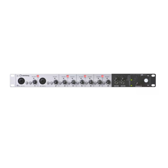
Page 4: Panel Controls And Terminals (Details)
Panel Controls and Terminals (Details) Panel Controls and Terminals (Details) Rear Panel DC IN 16V LINE OUTPUT 1–8 (phone type, balanced/unbalanced) For connection to the AC power adaptor. For connection to monitor speakers. When the Grounding screw monitor speakers have a balanced input, connect For connection to a ground wire. -
Page 5: Front Panel
Panel Controls and Terminals (Details) Front Panel MIC/LINE/HI-Z (XLR/phone type, SIG/PEAK lamp balanced/unbalanced) Indicates the input signal level of the analog input For connection to a microphone, digital jacks (MIC/LINE/HI-Z and MIC/LINE INPUT). instrument, electric guitar, or electric bass. Lamp status Description HI-Z switch -3 dB or more Turns on ( ) and off ( ) the HI-Z of the MIC/... - Page 6 Panel Controls and Terminals (Details) • Do not connect or disconnect a device while Sample rate lamp phantom power is applied. Doing so can damage the Indicates the sample rate of the device. connected device and/or the unit itself. • To protect your speaker system, leave the monitor Lamp Sample Rate speakers turned off when switching the phantom...
-
Page 7: Panel Controls For The Software Programs
The word clock signal input to the [Yamaha Steinberg USB Driver] WCLK IN. •From the Cubase series menu, [Devices] [Device Setup] [Yamaha Steinberg USB ASIO] ADAT A The word clock signal input to the [Control Panel] OPTICAL A IN. -
Page 8: Dspmixfx Ur824
This is the window for configuring the DSP mixer to the computer two or more devices compatible and DSP effect equipped with the device. The with the Yamaha Steinberg USB Driver. signals flow top-to-down and left-to-right. The Buffer Size dspMixFx UR824 provides stand-alone operation. -
Page 9: Main Window
Indicates the scene name. You can change the scene name by clicking on it. Windows [Start] [All Programs] [Steinberg UR824] When you click the button on the right side, the [dspMixFx UR824] window for calling up the scene will open. You can call up the scene by clicking it. - Page 10 Panel Controls for the Software Programs Channel Area Channel Strip Insertion Location Selects the insertion location of the Channel Strip. This is the area for configuring the input channel settings. Option Description MON.FX Applies the Channel Strip to only the monitor signal (sent to the device).
- Page 11 Panel Controls for the Software Programs DAW Area Master Area This is the area for configuring the DAW channel This is the area for configuring the master channel settings. settings. Level Meter Indicates the signal level. REV-X Send On/Off Turns the REV-X on (lit) and off (dark). You can turn this on for one of MIX 1–4.
-
Page 12: Setup Window
Panel Controls for the Software Programs REV-X Return Level Level Meter Window Adjusts the return level of the REV-X. This is the window for indicating the level meter of all channels on the upper part of the window. Also, this Range: -∞... - Page 13 Panel Controls for the Software Programs DIGITAL MODE KNOB MOUSE CONTROL Selects the input and output signal format of the Selects the method of operating the knobs on the OPTICAL A/B. dspMixFx UR824. Option Description Option Description ADAT This is an input and output signal Circular Drag in a circular motion to increase format supporting up to 8 channels.
-
Page 14: Dedicated Windows For Cubase Series
Panel Controls for the Software Programs Information Window Screenshot This window indicates information about the dspMixFx UR824 and the device. Input Settings Window Version Information Indicates the version of the firmware and software. The letters “x.x.x” and “x.xx” indicate the version number. Hardware Setup Window Check for update Checks whether or not you have the latest... - Page 15 Panel Controls for the Software Programs Click “Extended View Type/Can Hide State” In the VST Input Channel Settings Window in the input channel. (Cubase and Cubase Artist only) [Devices] [Mixer] to open the mixer. Click “Edit Input Channel Settings” in the input channel.
- Page 16 Panel Controls for the Software Programs Panel Controls Channel Strip Insertion Location Selects the insertion location of the Channel Strip. Input Settings Window Insertion Description location Upper Channel Strip is not applied. (OFF) Middle Applies the Channel Strip to only the (MON.FX) monitor signal (sent to the device).
- Page 17 Panel Controls for the Software Programs Hardware Setup Window REV-X Return Level Indicates the return level of the REV-X. Headphones Window REV-X Return Level knob This is the window for selecting the output signal of Adjusts the return level of the selected the PHONES on the device.
-
Page 18: Sweet Spot Morphing Channel Strip (Channel Strip)
Panel Controls for the Software Programs Sweet Spot Morphing Channel Master Level Indicates the output signal level of the LINE Strip (Channel Strip) OUTPUT. This is the window for configuring the Channel Strip Master Level knob settings. Adjusts the output signal level of the selected (highlighted) LINE OUTPUT signal. - Page 19 Panel Controls for the Software Programs Panel Controls ATTACK Adjusts the attack time of the compressor. Common to Compressor and Equalizer Range: 0.092 msec – 80.00 msec RELEASE Adjusts the release time of the compressor. Range: 9.3 msec – 999.0 msec RATIO Adjusts the ratio of the compressor.
-
Page 20: Rev-X
Panel Controls for the Software Programs REV-X Equalizer This is the window for configuring the REV-X settings. Three types of REV-X are available: Hall, Room, and Plate. NOTE •The REV-X equipped with the device and REV-X of the VST Plug-in version have the same parameters. However, the “OUTPUT”... - Page 21 Panel Controls for the Software Programs From the dspMixFx UR824 Room Size Adjusts the size of the simulated room. This Click “REV-X Edit” (page 11) in the section “Master parameter links to Reverb Time. Area.” Range: 0 – 31 Panel Controls Diffusion Adjusts the spread of the reverberation.
- Page 22 Panel Controls for the Software Programs MIX (VST Plug-in version only) Adjusts the output level balance between the original sound and effect sound. Range: 0% – 100% Time Axis Setting Select the display range of the time (horizontal axis) on the graph. Display range: 500 msec –...
-
Page 23: Usage Examples
It is assumed that the audio driver [Devices] [Device Setup] [Yamaha settings on the DAW software have been properly Steinberg USB ASIO] (Windows) or [Steinberg configured according to the “Basic Operation” UR824] (Mac) enter checkmark to “Direct section in the included Getting Started manual. -
Page 24: Connecting The Mic Preamp
Usage Examples Click “Record” to start the recording. Adjust the output signal level of the headphone by the PHONES knob on the device. Set the Channel Strip settings and REV-X settings on the dspMixFx UR824. After finishing the recording, click “Stop” to stop it. -
Page 25: Using The Device Without A Computer
Usage Examples Operation Connection Example Connect the optical output terminal (ADAT) Monitor speakers Synthesizer of the mic preamp to the OPTICAL A IN on the device. Connect the WCLK OUT on the device to the word clock input terminal on the mic preamp. -
Page 26: Appendix
Sweet Spot Data VST (Virtual Studio Technology) is a technology Sweet Spot Data are preset settings data of the developed by Steinberg which allows the integration Sweet Spot Morphing Channel Strip created by top- of virtual effect processors and instruments into your class engineers. -
Page 27: Contents Of The Getting Started Section
Appendix Contents of the Getting Started Section PRECAUTIONS Introduction A Message from the Development Team Included Accessories How to Read the Manual Panel Controls and Terminals Rear Panel Front Panel Setup 1. Setting up the Power Supply 2. Installing Cubase AI 3. -
Page 28: Signal Flow
Appendix Signal Flow The following chart indicates the signal flow in the device. NOTE •The controllers on the device, such as the HI-Z switch, INPUT GAIN knob, and OUTPUT LEVEL knob, are not included in this chart. •To configure each parameter, use the “dspMixFx UR824” (page 8) or “Dedicated Windows for Cubase Series” (page 14). - Page 29 Appendix *1The following chart indicates the Ch.Strip (Channel Strip) insertion location. Upper (INS.FX) Lower (MON.FX) Not applied (OFF) From input on the device From input on the device From input on the device Ch. Strip To DAW To DAW To DAW input input input...
-
Page 30: Block Diagrams
Appendix Block Diagrams UR824 – 44.1/48 kHz 8 Analog In/Out, 16 Digital In/Out, 26 DAW In/24 DAW Out 8+2 BUS Operation Manual UR824... - Page 31 Appendix UR824 – 88.2/96 kHz 8 Analog In/Out, 8 Digital In/Out, 18 DAW In/16 DAW Out 8+2 BUS Operation Manual UR824...
- Page 32 Steinberg Web Site http://www.steinberg.net C.S.G., Pro Audio Division © 2011 Yamaha Corporation 109MW-B0...