Table of Contents
Advertisement
Quick Links
Advertisement
Table of Contents

Related Manuals for IMC Networks AccessEtherLinX


Summary of Contents for IMC Networks AccessEtherLinX
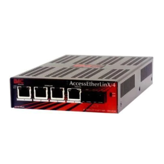
- Page 1 AccessEtherLinX Operation Manual...
-
Page 2: Fcc Radio Frequency Interference Statement
At its option, IMC Networks will repair or replace at no charge the product which proves to be defective within such warranty period. This limited warranty shall not apply if the IMC Networks product has been damaged by unreasonable use, accident, negligence, service or modification by anyone other than an authorized IMC Networks Service Technician or by any other causes unrelated to defective materials or workmanship. -
Page 3: Table Of Contents
Table of Contents FCC Radio Frequency Interference Statement ............ii Warranty........................ ii About the AccessEtherLinX..................1 Installing the AccessEtherLinX.................1 Features .........................2 About FiberAlert.....................3 About iView²......................4 SNMP Management ....................5 Configuring VLAN IDs ..................11 UMA (Unified Management Agent) ..............15 LED Operation.....................19 Passwords ......................20 Specifications .......................22... -
Page 4: About The Accessetherlinx
All features, such as FiberAlert and Auto-Negotiation, are software configurable. Place the AccessEtherLinX on a flat surface, prior to installation. Attach the cables between the AccessEtherLinX and each device that will be interconnected and then plug the unit into a reliable, filtered power source. -
Page 5: Features
Wall-Mount Installation To wall mount the AccessEtherLinX/3, use the supplied screws to attach the wall- mount bracket to the AccessEtherLinX/3, then mount the unit to the wall. Attach the cables between the AccessEtherLinX/3 and each device that will be interconnected and then plug the unit into a reliable, filtered power source. -
Page 6: About Fiberalert
If a strand is unavailable, the AccessEtherLinX notes the loss of link. The device will then stop transmitting data and the link signal until a signal or link pulse is received. The result is that the link LED on both sides of the fiber connection will go out, indicating a fault somewhere in the fiber loop. -
Page 7: About Iview²
32-bit Windows platform. iView² can also function as a snap-in module for many SNMP applications. Refer to the help files for iView² and AccessEtherLinX for information regarding configuring and managing the AccessEtherLinX. -
Page 8: Snmp Management
About Serial Port Configuration Use Downlink Port 3 on the AccessEtherLinX/3 to allow for serial port configuration and on Downlink Port 4 on the AccessEtherLinX/4 version. Use the supplied RJ-45 to DB9 serial connector. To connect the AccessEtherLinX to a terminal/computer, use a straight-through (pin- to-pin) cable. - Page 9 (15.24m). Plug one end of the cable into the DB-9 connector and the other into the appropriate computer/terminal port. Set the computer/terminal for VT-100 emulation, with: 38.4K baud, 8 data bits, 1 stop bit, no parity and no flow control. Serial Adapter Pin Connection RJ-45 Pin # DB-9 Pin #...
- Page 10 Command List • I = Enter New Saved Parameter Values • P = Change Password • T = New Trap Destination • K = Remove ALL Trap Destinations • C = New Community String • U = Delete ALL Community Strings •...
- Page 11 the name of the community string (that the destination device has been configured to accept) and press Enter. This function enables ALL of the device’s traps. To selectively activate and de-activate traps, use iConfig for configuration. Supported traps are Enterprise specific and include: Link Down, Link Up, Cold Start, Warm Start and Authentication Failure.
- Page 12 then issue an IP address to the management card. Once the new IP address is received, the SNMP Management Module will reboot so that the new IP address will take effect. Refer to the About Serial Port Configuration for more information about Enabling/Disabling DHCP.
-
Page 13: Downloading Files
*Perform a reboot after using the dlsecure and dl_open commands. Downloading Files Firmware for the AccessEtherLinX can be downloaded from a central server via TFTP protocol. Initiate this download via serial configuration or Telnet session. To download a file, type download and press Enter to be taken to the Download a file screen. -
Page 14: Configuring Vlan Ids
Configuring VLAN IDs The AccessEtherLinX is VLAN compatible, with the ability to accept traffic containing 802.1q VLAN tags on the Uplink port and direct that traffic to the twisted pair downlink ports. When using VLAN IDs, the SNMP must be assigned an ID or else the management and pinging features will not be available. - Page 15 NOTE SNMP can only be associated with one VLAN group. Tags cannot be enabled on SNMP traffic. Users can assign each port plus SNMP a priority in the VLAN Definition screen. The high and low priority is determined by the Base VLAN of the unit. Use iView² to set the Base VLAN priority;...
-
Page 16: Port Configuration
FiberAlert and Auto-Negotiation, etc. (This can also be performed via iView².) NOTE This screen shows the settings for the AccessEtherLinX/4 and includes information for the unit’s four downlink ports; the same screen for the AccessEtherLinX/3 will show information for the unit’s 3 ports. -
Page 17: Update Manager
Update Manager iView² offers the option of scheduling an update search for IMC Networks’ devices listed in the Network outline. Within iView², select Tools/SNMP Options from the navigation toolbar. Select Update Manager Options, and a dialog box will be displayed, in which you can select when to run the update search. -
Page 18: Uma (Unified Management Agent)
1.8 or higher AccessEtherLinx firmware ver C3 or higher For example, install 20 iMcV-FiberLinX-II devices in a 20 slot iMediaChassis at the Central Office (CO) then connect each to a remote AccessEtherLinX unit installed at the customers premise (CPE); UMA will then allow users to manage all 41 devices (including the chassis at the CO) via a single IP address. - Page 19 Using Telnet Assign the AccessEtherLinX an IP Address or use the default IP Address 10.10.10.10, subnet mask 255.0.0.0 before using a Telnet session. All configurations done via the serial port can also be performed using Telnet. Use only one Telnet session at a time.
- Page 20 Press the Space Bar Type “dl_open” as shown above...
- Page 21 Press Y to confirm this change Press any key Type reboot, and then press Enter to restart the system. When the system is done rebooting it should work like a media converter with a 4-port switch attached.
-
Page 22: Led Operation
LED Operation AccessEtherLinX/3 Uplink Port LNK/ACT* Glows green when link is established on port. Blinks green during data activity on port. *Located on RJ-45 of downlink port 3. Downlink Ports Glows amber when link is established on port. Blinks amber during data activity on port. -
Page 23: Passwords
Before using iView² iView² is a network management application designed for use on the IMC Networks Intelligent Networking Devices. It features a Graphic User Interface (GUI) and gives network managers the ability to monitor and control products from a variety of platforms, iView²... - Page 24 During the installation, the iView² application will ask if HP Open View is installed on the management PC. Click Yes to integrate the appropriate files. Once in OpenView, select IMC Networks from the toolbar to view the IMC Networks’ devices.
-
Page 25: Specifications
Storage Temperature -4° to 158° F (-20° to 70° C) Humidity 5 to 95% (non-condensing) Maximum heat generated 17 BTU/hr for AccessEtherLinX/3 50 BTU/hr for AccessEtherLinX/4 Power Consumption (typical) 650 mA for AccessEtherLinX/3 1.5 A for AccessEtherLinX/4 Throughput and VLAN Trunking Up to full wire speed on all ports except the third (3/port)/ fourth (4/port) downlink port (this port also functions as a serial port). -
Page 26: Imc Networks Technical Support
IMC Networks Technical Support Tel: (949) 465-3000 or (800) 624-1070 (in the U.S. and Canada); +32-16-550880 (Europe) Fax: (949) 465-3020 E-Mail: techsupport@imcnetworks.com Web: www.imcnetworks.com Electrostatic Discharge Precautions Electrostatic discharge (ESD) can cause damage to your add-in modules. Always observe the following precautions when installing or handling an add-in module or any board assembly. -
Page 27: Safety Certifications
Electrical Equipment Designed for use within Certain Voltage Limits (73/23/EEC). Certified to Safety of Information Technology Equipment, Including Electrical Business Equipment. For further details, contact IMC Networks. Class 1 Laser product, Luokan 1 Laserlaite, Laser Klasse 1, Appareil A’Laser de Classe 1... - Page 28 The information in this document is subject to change without notice. IMC Networks assumes no responsibility for any errors that may appear in this document. AccessEtherLinX is a trademark of IMC Networks. Other brands or product names may be trademarks and are the property of their respective companies.
Need help?
Do you have a question about the AccessEtherLinX and is the answer not in the manual?
Questions and answers