
Related Manuals for IMC Networks PoE Giga-MiniMc


Summary of Contents for IMC Networks PoE Giga-MiniMc
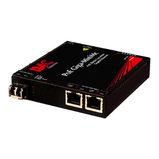
- Page 1 PoE Giga-MiniMc and PoE+ Giga-MiniMc Operation Manual Above illustration is representative; different models available.
-
Page 2: Fcc Radio Frequency Interference Statement
IMC Networks' instructions and directions for a period of six (6) years after the original date of purchase. IMC Networks warrants to the original end- user purchaser that all SFPs shall be free from defects in materials and workmanship under normal and proper use in accordance with IMC Networks' instructions and directions for a period of one (1) year after the original date of purchase. -
Page 3: Table Of Contents
LED Operation SFP and 1x9................4 Powering Option....................6 DIN Rail and Wallmount Bracket ...............6 DC Power Supply Precautions................8 Troubleshooting ....................8 Specifications for the PoE Giga-MiniMc............10 About the PoE+ Giga-MiniMc.................12 Installation .......................12 DIP Switch Configuration SFP and 1x9 .............13 LED Operation SFP and 1x9................15 Powering Options ....................17... -
Page 4: About The Poe Giga-Minimc
For example, connect a PoE Giga-MiniMc , TX/SSLX-SM1310-SC (which has 1310 xmt and 1550 rcv) to a product which has 1550 xmt PoE Giga-MiniMc and 1310 rcv, e.g. -
Page 5: Dip Switch Configuration Sfp And 1X9
Factory Set Do not change Factory Set Do not change LoSPd DSW for PoE Giga-MiniMc The DIP Switch for LoSPd is to allow the end user to set a speed for a fiber SFP under the following conditions: • Setting the LoSPd DSW to ON will force the SFP to operate at 100Mbps. When set in the default of OFF, the SFP will run at it’s maximum rate of the SFP... - Page 6 PoE Reset DSW When set to ON, it will force the PSE output power on the copper port OFF when the LINK state is lost on the SFP line (copper or fiber SFP). By default, the DSW is set to OFF. PoE Gig-MiniMc 1x9 Name Description...
-
Page 7: Led Operation Sfp And 1X9
LED Operation SFP and 1x9 The PoE Giga-MiniMc includes LEDs for three ports, as shown below: PoE Giga-MiniMc SFP SFP LED Functions are as follows: Glows red when a fault has been detected on the unit Glows green with a valid link... - Page 8 PoE Giga-MiniMc 1x9 1x9 LED Functions are as follows: Glows red when a fault has been detected on the unit Glows green with a valid link 1000 Mbps Glows green when is running at 1000Mbps Glows green when unit is powered...
-
Page 9: Powering Option
• The 4-terminal DC power block DC Terminal Block Wiring Instructions The PoE Giga-MiniMc can be powered via the DC terminal block. From a power source, connect to any one positive and any one negative terminal on PoE Giga- MiniMc. - Page 10 NOTE The DIN clips are designed for use on a DIN-35 rail. Wallmount Bracket Din Rail Mounting NOTE The DIN clips are designed for use on a DIN-35 rail. When using the side-installed location, remove the countersunk screw from the enclosure, and then use the vacated hole for one of the DIN clip screws.
-
Page 11: Dc Power Supply Precautions
Troubleshooting • PWR LED glows green when the unit is powered. If this LED is not lit, contact IMC Networks Technical Support. • If the PSE LED flashes twice, it may indicate an over current condition. The PSE LED should maintain solid green, to indicate consistent power. Check the PD... - Page 12 The following table lists the pin configuration for the RJ-48 connector. Pin# Signal Name Signal Direction 1000M 10/100M PoE+ (ALT-B) TXD1+ Out* TXD1- Out* RXD2+ RXD2-...
-
Page 13: Specifications For The Poe Giga-Minimc
Specifications for the PoE Giga-MiniMc Multi-mode 1300nm Dual Fiber Single-mode 1310nm 1550nm Dual Fiber Single-mode 1310nm 1490nm Single-Strand Fiber Single-mode 1310nm 1550nm Single-Strand Fiber Copper 10/100/1000Mbps Ethernet Connections 10/100/1000 BaseT Auto Negotiation AutoCross Flow Control 10240 MTU Full Line-Rate Forwarding... - Page 14 Standards Compliance IEEE 802.3af Power Over Ethernet IEEE 802.3 Ethernet Standards IEEE 802.3u Auto-Negotiation RFC-2474 RFC-2475 DiffServ QoS IMC Networks Products Length of Warranty SFPs 1 year PoE Giga-MiniMc 6 year NOTE Please refer to the Warranty Section at the beginning of this manual for the full...
-
Page 15: About The Poe+ Giga-Minimc
PoE+ Giga-MiniMc in locations with extremely limited space. Velcro strips are also included to attach the device to most surfaces. The DIN Rail clips and Wallmount bracket are optional, available for purchase through an IMC Networks Distributor. Installation Tip Several models of the PoE+ Giga-MiniMc support single-strand fiber for operation. -
Page 16: Dip Switch Configuration Sfp And 1X9
DIP Switch Configuration SFP and 1x9 PoE+ Giga-MiniMc SFP Name Definition Default Switch Setting PoE Reset 2 ON forces Port 2 PoE OFF on LOS of Fiber input PoE Reset 1 ON forces Port 1 PoE OFF on LOS of Fiber input LoSpd ON sets SFP for low speed operation... - Page 17 PoE+ Giga-MiniMc 1x9 Name Description Default Switch Setting PoE Reset 2 ON forces Port 2 PoE OFF on LOS of Fiber input PoE Reset 1 ON forces Port 1 PoE OFF on LOS of Fiber input Factory Set Do not change Factory Set Do not change Factory Set...
-
Page 18: Led Operation Sfp And 1X9
LED Operation SFP and 1x9 The PoE+ Giga-MiniMc includes LEDs for three ports, as shown below: PoE+ Giga-MiniMc SFP SFP LED Functions are as follows: Glows red when a fault has been detected on the unit Glows green with a valid link 1000 Mbps Glows green when SFP is running at 1000Mbps Glows green when unit is powered... - Page 19 PoE+ Giga-MiniMc 1x9 1x9 LED Functions are as follows: Glows red when a fault has been detected on the unit Glows green with a valid link 1000 Mbps Glows green to indicate is running at 1000Mbps Glows green when unit is powered RJ-45 LED Functions are as follows: LNK/ACT Glows green with a valid link...
-
Page 20: Powering Options
Powering Options As a standalone unit, the PoE+ Giga-MiniMc uses a universal external desktop switching power adapter. The PoE+ Giga-MiniMc also includes a DC terminal block to support a voltage range of 51 to 57 VDC. PoE+ Giga-MiniMc supports two powering options. •... -
Page 21: Din Rail And Wallmount Bracket
The PoE+ Giga-MiniMc can be mounted with two DIN Rail clips, a hardware option available through IMC Networks. The DIN Rail clips include screws, to allow the installation onto a DIN Rail. Install the screws into DIN Rail clips, which should be mounted perpendicular to the DIN Rail. -
Page 22: Dc Power Supply Precautions
There may be an invalid low or high discovery signature resistance; this is indicated on the PSE LED by a series of five flashes. • If the PoE injector has power that can be verified, but the PSE LED is off, then contact IMC Networks technical support. -
Page 23: Rj-45 Pinouts
RJ-45 Pinouts The following table lists the pin configuration for the RJ-48 connector. Pin# Signal Name Signal Direction Pin# 1000M 10/100M PoE+ (ALT-B) TXD1+ Out* TXD1- Out* RXD2+ RXD2-... -
Page 24: Specifications For The Poe+ Giga-Minimc
Specifications for the PoE+ Giga-MiniMc Multi-mode 1300nm Dual Fiber Single-mode 1310nm 1550nm Dual Fiber Single-mode 1310nm 1490nm Single-Strand Fiber Single-mode 1310nm 1550nm Single-Strand Fiber Copper 10/100/1000Mbps Ethernet Connections 10/100/1000 BaseT Auto Negotiation AutoCross Flow Control 10240 MTU Full Line-Rate Forwarding DC Input Voltage 51 to 57 VDC on DC terminal block 51 to 57 VDC on DC jack... -
Page 25: Poe Precautions (For Inside-A-Building Installation Only)
Both devices cannot be installed outside-a-building environment, as they cannot meet the PoE requirements, per the PoE standard. If installing the device outside, serious damage can occur and void the IMC Networks’ warranty. IMC Networks Technical Support Tel: (949) 465-3000 or (800) 624-1070 (in the U.S. and Canada);... -
Page 26: Fiber Optic Cleaning Guidelines
Dust caps are installed at IMC Networks to ensure factory-clean optical devices. These protective caps should not be removed until the moment of connecting the fiber cable to the device. Should it be necessary to disconnect the fiber device, reinstall the protective dust caps. -
Page 27: Safety Certifications
Directive on Electrical Equipment Designed for use within Certain Voltage Limits (2006/95/EC). Certified to Safety of Information Technology Equipment, Including Electrical Business Equipment. For further details, contact IMC Networks. Class 1 Laser product, Luokan 1 Laserlaite, Laser Klasse 1, Appareil A’Laser de Classe 1... - Page 28 The information in this document is subject to change without notice. IMC Networks assumes no responsibility for any errors that may appear in this document. PoE Giga-MiniMc and PoE+ Giga-MiniMc is a trademark of IMC Networks. Other brands or product names may be trademarks and are the property of their respective companies.
Need help?
Do you have a question about the PoE Giga-MiniMc and is the answer not in the manual?
Questions and answers