Table of Contents
Advertisement
Quick Links
Advertisement
Table of Contents
Troubleshooting

Related Manuals for IMC Networks iMcV-Giga-FiberLinX-II


Summary of Contents for IMC Networks iMcV-Giga-FiberLinX-II
- Page 1 Operation Manual...
-
Page 2: Fcc Radio Frequency Interference Statement
IMC Networks' instructions and directions for a period of six (6) years after the original date of purchase. IMC Networks warrants to the original end- user purchaser that all SFPs shall be free from defects in materials and workmanship under normal and proper use in accordance with IMC Networks' instructions and directions for a period of one (1) year after the original date of purchase. -
Page 3: Table Of Contents
Bandwidth Configuration—bw-------------------------------------------------------------- 27 VII - Application Overview ---------------------------------------------------------------------- 28 How many iMcV-Giga-FiberLinX-II units will you use?--------------------------------- 28 How do you want to manage iMcV-Giga-FiberLinX-II? -------------------------------- 28 Will you define VLAN IDs? ------------------------------------------------------------------ 29 VIII - Application Examples---------------------------------------------------------------------- 29 Default ------------------------------------------------------------------------------------------- 29... - Page 4 Transparent with Extra Tagging (Q-in-Q)-------------------------------------------------- 34 Port VLAN--------------------------------------------------------------------------------------- 36 Port VLAN Filter-------------------------------------------------------------------------------- 40 IX - Troubleshooting ------------------------------------------------------------------------------ 43 Troubleshooting LinkLoss/FiberAlert/Link Fault Pass-Through------------------------- 45 IMC Networks Technical Support-------------------------------------------------------------- 50 Specifications -------------------------------------------------------------------------------------- 50 Standards/Compliance --------------------------------------------------------------------------- 50 Serial Port Pinout---------------------------------------------------------------------------------- 51 Safety Certifications------------------------------------------------------------------------------- 55...
-
Page 5: I - About The Imcv-Giga-Fiberlinx-Ii
In addition, a range of fiber connectors (SC, ST, or SFP) and a variety of wavelengths, supporting higher density CWDM and single-strand fiber operation are available. The iMcV-Giga-FiberLinX-II supports two main configuration modes: Standalone or Host/Remote. When using Host/Remote, the Remote modules can be fully managed without an IP address using a secure management channel (when the SNMP module is installed in the same chassis). -
Page 6: Serial Craft Port Connection
In addition, a DB-9 port is available for management through a serial port connection. Refer to Serial Port Pinout on page You can easily configure the iMcV-Giga-FiberLinX-II by using either the serial craft port connection, through SNMP management application such as iView² or a Telnet session. -
Page 7: Iview Management Software
Management Software iView² is the IMC Networks management software designed specifically for the IMC Networks “iMcV” family of modules. It features a graphical user interface (GUI) and gives network managers the ability to monitor and control the manageable IMC Networks products. -
Page 8: About Dynamic Host Control Protocol (Dhcp)
The server will then issue an IP address, Default Gateway address and Subnet mask to the module. After the new IP address is received, the iMcV-Giga-FiberLinX-II will reboot with the new IP address. When a DHCP server is not on the network, ensure that DHCP is disabled an iConfig or serial configuration to manually set the IP addresses (refer to the Serial Configuration/Telnet Session section for DHCP Enable/Disable information). -
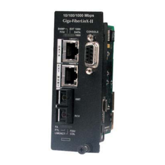
Page 9: Led Operation
II - LED Operation The following are iMcV-Giga-FiberLinX-II diagnostic LEDs. In this example, the functions for a 1x9 fiber port version (SC fiber) are shown below. In the SFP/SFP version the LNK/ACT and FDX/COL LEDs replace EXT 1000 and DATA 1000 for the top SFP, which does not have built-in LEDs like the RJ-45 DATA port. -
Page 10: Hardware Configuration
Refer to the Application Examples section for examples. When two iMcV-Giga-FiberLinX-II units are used as a pair, configure one as a Host unit (DIP switch 8 = ON) and the other as a Remote unit (DIP switch 7 = ON). As a host unit, the iMcV-Giga-FiberLinX-II requests management information from the attached remote unit. -
Page 11: Management
SNMP. As a Remote unit, the iMcV-Giga-FiberLinX-II will respond to requests for management information from an attached Host unit. The iMcV-Giga-FiberLinX-II default configuration is as a Standalone unit (DIP switches 7 and 8 = OFF). Management Although the iMcV-Giga-FiberLinX-II provides a twisted pair port solely for management (EXT MGMT), you can configure iMcV-Giga-FiberLinX-II to accept IP- based management traffic from any of its three ports. -
Page 12: Installation Instructions
The iMcV-Giga-FiberLinX-II module includes on-board SNMP logic. A chassis other than an iMediaChassis series cannot manage an iMcV-Giga-FiberLinX-II, so the iMcV- Giga-FiberLinX-II must be managed independently. When installed in an iMediaChassis, you can manage the iMcV-Giga-FiberLinX-II module from the chassis by using the Unified Management Agent (UMA). -
Page 13: Assigning Ip Information
Assigning IP Information When the iMcV-Giga-FiberLinX-II is installed in an iMediaChassis, you can use UMA to manage your iMcV-Giga-FiberLinX-II without an IP address (refer to the iView² online help for more information on UMA). When the iMcV-Giga-FiberLinX-II is not installed in an iMediaChassis, SNMP-management is not accessible until the iMcV- Giga-FiberLinX-II IP information (e.g., IP address, subnet mask, etc.) is configured... -
Page 14: Bandwidth Control
DATA Port to the OPTICS (or UPLINK) Port and vice versa in a single iMcV-Giga- FiberLinX-II application. In a dual iMcV-Giga-FiberLinX-II application you can set it from the Host unit to the Remote unit and vice versa (i.e., the bandwidth on the DATA ports on both the Host and Remote modules can be limited independently). -
Page 15: Link Fault Pass-Through
Link Fault Pass-Through Link Fault Pass-Through (LFPT) is a troubleshooting feature that combines TX and FX LinkLoss from both the local and remote iMcV-Giga-FiberLinX-II modules. LFPT is enabled by turning on both FX and TX LinkLoss on both modules. This feature allows... -
Page 16: Loopback Testing On Remote Or Standalone
Loopback Testing on Remote or Standalone The following functions are available during loopback testing. During loopback testing, management traffic entering the uplink port is still capable of managing the device. Address Swap A Layer 2 Ethernet switch will discard all received packets with the same MAC address as sent packets. -
Page 17: Using Telnet
VI - Using Telnet You must assign the iMcV-Giga-FiberLinX-II an IP address before using a Telnet session (this is not necessary when you are using UMA). Refer to the Assigning IP Information section for more information. All of the configurations that you can perform from the serial port can also be performed using a Telnet session. -
Page 18: Basic Device Configuration
Basic Device Configuration After running through an initial self test, the prompt: “Press <Enter> for Device Configuration” displays. Press Enter to open the Main Configuration screen: Saved Values. <These values will be active after reboot> IP Address 10.10.10.10 Subnet Mask 255.0.0.0 Default Gateway - 000.000.000.000... - Page 19 Passwords are a way to make the management of the IMC Networks devices secure. It is your responsibility to store and maintain the password lists. If the passwords are lost, neither you nor IMC Networks has a way to "decode" it. Refer to the iView² iConfig online help for more password information.
- Page 20 Supported traps include: Link Down, Link Up, Cold Start, Warm Start, and Authentication Failure. When deployed in pairs, iMcV-Giga-FiberLinX-II also supports the following traps: • Remote Unit Lost •...
-
Page 21: (Space Bar)-Commands List
By default, the DHCP client is disabled. (Space Bar)—Commands List The iMcV-Giga-FiberLinX-II also includes several device-specific options. To access these options, press the space bar from the Main Configuration screen, type the command name of the action you want to perform (as shown below) and press Enter. -
Page 22: Clean Database-Cleandb
IP Subnet, Gateway, VLAN settings, CLI command settings, serial port password, and security settings. Downloading Files—download The iMcV-Giga-FiberLinX-II allows you to download firmware from a central server by using TFTP. To download firmware by using either a serial connection or a Telnet session, do the following: 1. -
Page 23: Port Configuration-Port
8. Press Q or F4 to return to the Device-Specific Options screen. When the iMcV-Giga-FiberLinX-II is installed in a managed chassis, you have the option of using UMA to update the firmware (refer to the iView information on using UMA with iConfig, iMediaChassis and iMcV-Giga-FiberLinX-II). -
Page 24: Mode Configuration-Config
This allows you to advertise all speeds and duplex modes. You must enable autonegotiation for selective advertising to work. If a specific speed and/or duplex mode are desired, IMC Networks recommends using selective advertising, instead of force mode (FO), when connecting to devices that can only autonegotiate. -
Page 25: Transparent Mode
Default mode is the factory default and is provided as a starting point from which to configure the iMcV-Giga-FiberLinX-II modules. This mode does not provide full management isolation and is not recommended for normal use. This section describes the Telnet/serial port screens and fields available for configuring the iMcV-Giga-FiberLinX-II modes. -
Page 26: Transparent With Vlan Tag On Ext Mgmt Port
If the device is currently managed on any port other than the EXT MGMT port, do not leave the Management Tag field defined as zero (0). This will disable management traffic on the iMcV-Giga-FiberLinX-II. You must enter a VLAN ID between 1 and 4094 (excluding the VLAN ID used for the... -
Page 27: Vlan Mode Screen
TRANSPARENT MODE SETUP Is a VLAN tag required on Management packets? [ Y ] The Management Tag is [7 Management Priority is [0 re VLAN Tags required on the EXT Port? Do you want to enter the Extra Tag mode? Ent nter N if you do not want Extra Tags [ N ] Type S or F3 to save the new information ype Q of F4 to quit and cancel changes... -
Page 28: Port Vlan On Data Port
No VLANs are defined allowing only untagged packets to pass through the unit. Port VLAN on OPTICS (or UPLINK) port This parameter allows you to restrict traffic to a single VLAN ID tag for the OPTICS (or UPLINK) port by entering Y in the Tags column of the Optics row. In the VLAN IDs - Saved column of the Data row, enter the VLAN ID tag to be used (in this example, 13). -
Page 29: Unit Configuration-Unit
VLAN ID between 1 and 4094 (excluding the VLAN IDs used for the Port VLAN or for the Data VLANs). Unit Configuration—unit The iMcV-Giga-FiberLinX-II allows you to view unit status as well as configure some unit features by using a serial connection or a Telnet session. In the Main Priorities... - Page 30 Configuration screen, press the space bar, type unit, and press Enter to open the Unit Control Settings screen. In this screen you can view the unit FlowControl, FiberAlert/LinkLoss, Loopback, Maximum Frame Size, and 802.1p Base Priority (logging-in as a User in a Telnet session allows you to view these settings but prevents you from changing the settings).
-
Page 31: Bandwidth Configuration-Bw
For example, 0. Bandwidth Configuration—bw The iMcV-Giga-FiberLinX-II allows you to view bandwidth status and to configure bandwidth from a serial connection or a Telnet session. In the Main Configuration screen, press the space bar, type bw and, then press Enter to access the Bandwidth... -
Page 32: Application Overview
VII - Application Overview Before using iMcV-Giga-FiberLinX-II in your network, decide the following: • Will iMcV-Giga-FiberLinX-II units be located at only one or at both ends of the fiber? • How do you want to manage the iMcV-Giga-FiberLinX-II units? •... -
Page 33: Will You Define Vlan Ids
Default mode passes only untagged data between the DATA port and the OPTICS (or UPLINK) port. This mode is the factory default and is provided as a starting point from which to configure the iMcV-Giga-FiberLinX-II modules. It is not intended as a mode for normal use. -
Page 34: Transparent With Untagged Management
Transparent with Untagged Management Transparent with Untagged Management mode passes tagged traffic between the DATA port and the OPTICS (or UPLINK) port and allows untagged traffic to be considered management domain traffic (untagged). To configure this mode, do the following: 1. - Page 35 The flow of management domain traffic is defined by the DIP switches. For example, if the management DIP switches are on the OPTICS and DATA ports, management domain traffic is allowed to flow through those ports. External Management is ON OPTICS: Tagged Data and Untagged...
-
Page 36: Transparent With Tagged Management
Transparent with Tagged Management Transparent with Tagged Management mode passes both tagged and untagged traffic between the DATA port and the OPTICS (or UPLINK) port. By using a VLAN Tag you can isolate and route the management path in the module. This method can be used with or without continuing the management path down the EXT MGMT port. - Page 37 Type reboot. Now the iMcV-Giga-FiberLinX-II is configured to pass all data between the OPTICS (UPLINK) and DATA ports, except data tagged with VLAN ID 7. All data tagged with VLAN ID 7 is considered management traffic and passes from the OPTICS (UPLINK) port to the EXT MGMT port only.
-
Page 38: Transparent With Extra Tagging (Q-In-Q)
DATA port. By using Extra Tagging in a Host/Remote iMcV-Giga-FiberLinX-II pair, all data received on the Remote iMcV-Giga-FiberLinX-II DATA port can be extra-tagged and sent out of the Host iMcV-Giga-FiberLinX-II DATA port with a unique tag for identification in the Host cloud. In the reverse direction the extra tag is removed before sending the data out of the Remote iMcV-Giga-FiberLinX-II DATA port. - Page 39 II. VLAN ID 8 tag is removed before sending the data out of the Remote DATA port. The Extra Tag VLAN ID 8 is added to all data received on the Remote DATA port before being sent to the Host iMcV-Giga-FiberLinX-II where the VLAN ID 8 tag remains on the data leaving the Host DATA port.
-
Page 40: Port Vlan
Port VLAN The Port VLAN mode allows you to configure the iMcV-Giga-FiberLinX-II to accept only data tagged with one specific VLAN ID. This mode can be configured for either the OPTICS (or UPLINK) port or the DATA port. VLAN on DATA Port–Configuration To configure this mode, perform the following: In the Main Configuration screen, press the space bar and type config. - Page 41 Press S or F3 to save the settings. Type reboot. Now the iMcV-Giga-FiberLinX-II is configured to pass only VLAN ID 13 from the DATA port to the OPTICS (or UPLINK) port. Untagged packets arriving at the OPTICS (or UPLINK) port (Tags = N) receive a tag (VLAN ID = 13) before being sent out of the DATA port.
- Page 42 VLAN on OPTIC Port–Configuration To configure this mode, do the following: In the Main Configuration screen, press the space bar and type config. The Configuration screen displays: Transparent Mode – with either (not both) Data and Optics Mgmt dipswitches set to on, all traffic passes between Optics and Data port EXCEPT what has been defined as the Management Domain.
- Page 43 Press S or F3 to save the settings. Type reboot. The iMcV-Giga-FiberLinX-II is now configured to pass only VLAN ID 13 from the OPTICS (or UPLINK) port to the DATA port. Untagged packets arriving at the DATA port (Tags = N) receive a tag (VLAN ID = 13) before being sent out of the OPTICS (or UPLINK) port.
-
Page 44: Port Vlan Filter
Port VLAN Filter The VLAN filter mode allows you to isolate a segment of the network to only accept data using some or all of the 32 available VLAN IDs. To configure this mode, do the following: In the Main Configuration screen, press the space bar and type config. The Configuration screen displays: Transparent Mode –... -
Page 45: Type Reboot
Enter up to 32 VLAN IDs in the Data VLANs rows. VLAN IDs can range from 1 to 4094. Only the VLANs in this list will pass through the unit. Data VLANs <Optics <----> Data> VLAN 1 [0 [101 ] VLAN 12 [0 VLAN 2 [0 [102 ] VLAN 13 [0 VLAN 3 [0... - Page 46 Now the iMcV-Giga-FiberLinX-II is configured to pass only packets with tags containing the VLAN IDs defined in the Data VLANs table. VLAN ID numbers defined in this table must not be the same as the number used for the Management VLAN ID.
-
Page 47: Troubleshooting
1550 nm and receives 1310 nm. • If using an iMcV-Giga-FiberLinX-II unit with an SFP port and it is not functioning properly or at all, ensure the installed SFP module is the correct speed (1000 Mbps). - Page 48 Line section for more information). This is especially helpful if you feel you have configured the module improperly. If restarting to factory defaults is necessary, IMC Networks recommends using this function on both units in Host/Remote applications, and then reconfiguring all settings.
-
Page 49: Troubleshooting Linkloss/Fiberalert/Link Fault Pass-Through
The following diagrams show you how the different troubleshooting configurations for the iMcV-Giga-FiberLinX-II. The iMcV-Giga-FiberLinX-II also sends out link pulses from its copper and fiber transmitters, but normally has no way of knowing whether the cable to the other device is intact and the link pulses are reaching the other end. The combination of FiberAlert and LinkLoss allows this information to be obtained, even when physical access to a remote device is not available. - Page 50 FX LinkLoss Normally when a fault occurs on the fiber segment of an iMcV-Giga-FiberLinX-II conversion, only the fiber port LEDs on the modules indicates a fault. None of the devices connected to the RJ-45 ports are aware of the fault.
- Page 51 TX LinkLoss When a fault occurs on a twisted pair segment joining a device to an iMcV-Giga-FiberLinX-II module, the link fault is not detected by the device connected to the iMcV-Giga-FiberLinX-II module by fiber. When TX LinkLoss is enabled on the remote iMcV-Giga-FiberLinX-II module, a twisted pair fault turns off the fiber port transmitter.
- Page 52 FiberAlert Do not enable FiberAlert at both ends. This can cause the fiber link to lock When FiberAlert is enabled on the remote module (preferred use), a fault on the receive side of the OPTICS (or UPLINK) port causes the transmitter side to turn off. This allows the fiber connected device to detect a fault in its transmission fiber.
- Page 53 Link Fault Pass-Through...
-
Page 54: Imc Networks Technical Support
IMC Networks Technical Support Tel: (949) 465-3000 or (800) 624-1070 (in the U.S. and Canada); +32-16-550880 (Europe) Fax: (949) 465-3020 E-Mail: techsupport@imcnetworks.com Web: www.imcnetworks.com Specifications Power Consumption (Typical): 0.670 A @ 5 V Operating Temperature: 32° to 122° F (0° to 50° C) Storage Temperature: 0°... -
Page 55: Serial Port Pinout
Serial Port Pinout The iMcV-Giga-FiberLinX-II features a serial port that uses an IBM-compatible DB-9 serial connector. To connect an iMcV-Giga-FiberLinX to your workstation, use a straight-through (pin-to-pin) cable. If your workstation has a serial port using a connection not compatible with a DB-9 COM port, use the pin connection chart for reference in making a cable. - Page 56 Notes...
- Page 57 Notes...
- Page 58 Notes...
-
Page 59: Safety Certifications
Electrical Equipment Designed for use within Certain Voltage Limits (73/23/EEC). Certified to Safety of Information Technology Equipment, Including Electrical Business Equipment. For further details, contact IMC Networks. Class 1 Laser product, Luokan 1 Laserlaite, Laser Klasse 1, Appareil A’Laser de Classe 1... - Page 60 © 2007 IMC Networks. All rights reserved. The information in this document is subject to change without notice. IMC Networks assumes no responsibility for any errors that may appear in this document. iMcV-Giga-FiberLinX-II is a trademark of IMC Networks. Other brands or product names may be trademarks and are the property of their respective companies.
Need help?
Do you have a question about the iMcV-Giga-FiberLinX-II and is the answer not in the manual?
Questions and answers