
Related Manuals for IMC Networks iMcV-FiberLinX-II


Summary of Contents for IMC Networks iMcV-FiberLinX-II
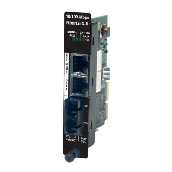
- Page 1 Operation Manual Above illustrations are representative; some minor differences may be present in actual product...
-
Page 2: Fcc Radio Frequency Interference Statement
At its option, IMC Networks will repair or replace at no charge the product which proves to be defective within such warranty period. This limited warranty shall not apply if the IMC Networks product has been damaged by unreasonable use, accident, negligence, service or modification by anyone other than an authorized IMC Networks Service Technician or by any other causes unrelated to defective materials or workmanship. -
Page 3: Table Of Contents
Table of Contents FCC Radio Frequency Interference Statement ------------------------------------------------- ii Warranty ----------------------------------------------------------------------------------------------- ii About the iMcV-FiberLinX-II ----------------------------------------------------------------------- 1 iView Management Software --------------------------------------------------------------------- 4 Installation --------------------------------------------------------------------------------------------- 5 Small Form-Factor Pluggable Ports (SFP) ----------------------------------------------------- 5 LED Operation ---------------------------------------------------------------------------------------- 6 TX/FX LEDs ----------------------------------------------------------------------------------------- 6... -
Page 4: About The Imcv-Fiberlinx-Ii
About the iMcV-FiberLinX-II NOTE Unless noted otherwise, all references to the iMcV-FiberLinX-II in this manual are also applicable to the iMcV-FiberLinX-II TX/SFP and iMcV-FiberLinX-II SFP/SFP. Overview The iMcV-FiberLinX-II allows network operators to deploy managed Ethernet services, with a full range of remote management, traffic monitoring, and alarm reporting features. -
Page 5: Port Interfaces
SNMP management application such as iView² or a Telnet session. About Serial Port Configuration The iMcV-FiberLinX-II includes a serial port on the unused pins of the EXT MGMT Ethernet port. Connect a local management PC using the included RJ-45 to DB-9 adapter (please refer to the appendix). - Page 6 When there is no DHCP server on the network, use iConfig or serial configuration to manually set the IP addresses. When DHCP is enabled, the IP address (default 10.10.10.10 or user configured) is saved. When DHCP is disabled, the saved IP address will be reinstated and the device will reboot.
-
Page 7: Iview 2 Management Software
Management Software iView² is the IMC Networks management software designed specifically for the IMC Networks iMcV family of modules. It features a Graphical User Interface (GUI) and gives network managers the ability to monitor and control the manageable IMC Networks products. -
Page 8: Installation
Tables > SFP Info. NOTE iMcV-FiberLinX-II has been tested with the IMC Networks SFP modules, so it is possible to install any MSA-compliant SFP module. However, IMC Networks does not guarantee the functionality of non-IMC Networks SFP modules due to possible non-conformity with MSA design standards. -
Page 9: Led Operation
LED Operation iMcV-FiberLinX-II features diagnostic LEDs as shown below. TX/FX LEDs FDX/COL: • Glows yellow when port is operating in Full-Duplex. • Blinks yellow when collisions occur on port. LNK/ACT: • Glows green when link is established on port. •... -
Page 10: Tx/Sfp Leds
TX/SFP LEDs LNK/ACT: • Glows green when link is established on port. • Blinks green during data activity on port. FDX: • Glows yellow when port is operating in Full-Duplex. • Blinks yellow when collisions occur on port. Diagnostic LEDs Optics Port LEDs FCU (Far CPU Up): Glows green when FiberAlert is... -
Page 11: Sfp/Sfp Leds
SFP/SFP LEDs LNK/ACT: • Glows green when link is established on port. • Blinks green during data activity on port. FDX: • Glows yellow when port is operating in Full-Duplex. • Blinks yellow when collisions occur on port. Diagnostic LEDs Optics Port LEDs FCU (Far CPU Up): Glows green when FiberAlert is... -
Page 12: Hardware Configuration
Application Examples section for examples. When two iMcV-FiberLinX-II units are used as a pair, configure one as a Host unit (DIP Switch 8 = On) and the other as a Remote unit (DIP Switch 7 = On). As a host unit, the iMcV-FiberLinX-II requests management information from the attached remote unit. - Page 13 Serial port management of the unit is always available on the EXT MGMT port regardless of the DIP Switch settings. In addition to defining which ports are used to manage the iMcV-FiberLinX-II units, the management DIP Switch settings also define what ports the flow of the Network Provider’s Management Domain traffic can take through the unit.
-
Page 14: Software Configuration
Assigning IP Information When the iMcV-FiberLinX-II is installed in an iMediaChassis, use UMA to manage the iMcV-FiberLinX-II without an IP address (refer to the iView² online help for more information on UMA). When the iMcV-FiberLinX-II is not installed in an iMediaChassis, SNMP-management is not accessible until the iMcV-FiberLinX-II IP information (e.g., IP address, subnet mask, etc.) is configured (using iConfig, a serial... -
Page 15: Configuration File Save/Restore Function
Requirements FiberLinX-II family series: Minimum firmware version required: A4 iMcV-FiberLinX-II: A1 or higher, Required iView² version: 1.8.4 or higher The Configuration File Save/Restore Function allows a user the ability to backup all the configuration settings of a unit. With this backup, a user can restore settings to a unit if necessary or use this backup to apply the same settings to a different unit. -
Page 16: Configuration File Basics
Once the file is saved to disk it can be restored to the device or sent to another like device through iConfig or TFTP. For iConfig The user will log into a unit, select the Administration tab, select the Upload Configuration button, be prompted to locate a configuration file on the PC’s disk. - Page 17 The user is prompted for a filename: The user is prompted to enter any notes to the header of the saved file for future reference when uploading the file through iConfig:...
-
Page 18: Uploading A Saved Configuration File Through Iconfig
After the file transfer from the device to disk, the user is notified of the status: Uploading a Saved Configuration File through iConfig From the Administration Tab in iConfig click the Upload Configuration button: The user will be prompted to select a configuration file. Once selected, the user can also view any notes that were added when the file was saved:... -
Page 19: Uploading A Saved Configuration File Through Tftp
After selecting the configuration file, the file upload process begins; when completed, the user is notified of the status and also notified that a reboot is necessary for the new configuration to become active: Uploading a Saved Configuration File through TFTP From the commands list in the CLI (Serial or Telnet) run the download command by typing in download:... - Page 20 In the download command screen type in the IP Address of the TFTP server and the file name to retrieve. The user will be prompted to continue that retrieval process by pressing the ENTER key or cancel by typing “Q”.
- Page 21 During normal operation, link integrity pulses are transmitted by all point-to-point Ethernet devices. When an iMcV-FiberLinX-II receives valid link pulses, it knows that the device to which it is connected is up, and that the copper or fiber cable coming from that device is intact.
- Page 22 Fiber Twisted Pair ** WARNING ** Do not enable FiberAlert on both modules when using iMcV-FiberLinX-II in pairs. This will cause them to lock up when a fault occurs on the fiber. Only enable FiberAlert on the remote module. Link Fault Pass Through (LFPT) Link Fault Pass Through is a troubleshooting feature that combines TX and FX LinkLoss from both the local and remote modules.
-
Page 23: Loopback Testing
Last Gasp The iMcV-FiberLinX-II includes a Last Gasp feature, which sends a trap Flinx Unit Down for the Host unit or a Flinx Remote Unit Down for the Remote unit (as seen in iView²) when the power to the module fails. -
Page 24: Broadcast Storm Protection
Loopback Testing in a Host/Remote Configuration Configure the Host by selecting No Learning on OPTICS and DATA Ports; on the Remote, choose SRC/DST Address Swap or Address Swap and Clear Multicast Bit. No Learning on OPTICS and DATA Ports The Loopback feature can be set to disable address learning on the OPTICS (or UPLINK) and DATA ports, allowing the loopback to be performed without interference from MAC address filtering functions. -
Page 25: Using Telnet
Using Telnet It is necessary to assign the iMcV-FiberLinX-II an IP address before using a Telnet session (this is not necessary when using UMA). Refer to the Assigning IP Information section for more information. All of the configurations that can be performed from the serial port can also be performed using a Telnet session;... -
Page 26: Basic Device Configuration
Basic Device Configuration After running through an initial self test, the screen will display the following message: Press <Enter> for Device Configuration. Press Enter open the main configuration screen: Saved Values. <These values will be active after reboot> IP Address 10.10.10.10 Subnet Mask 255.0.0.0... -
Page 27: Assigning Ip Information
NOTE It is necessary to reboot the iMcV-FiberLinX-II after making any modifications to the Saved Values for the changes to take effect. To reboot, type Reboot at the prompt on the Main Configuration screen. Assigning IP Information To modify the Saved Parameter Values (i.e., assign the IP address and subnet mask), press I. - Page 28 Supported traps include: Link Down, Link Up, Cold Start, Warm Start, Last Gasp, and Authentication Failure. When deployed in pairs, iMcV-FiberLinX-II also supports the following traps: • Remote Unit Lost • Remote Unit Found • Far End TX Link Up •...
-
Page 29: Enabling Dhcp
By default, the DHCP client is disabled. Commands List (Space Bar) The iMcV-FiberLinX-II also includes several device-specific options. To access these options, press the Space Bar from the Main Configuration screen, type the name of the action to be performed (as shown below) and press Enter. - Page 30 8. Press Q or F4 to return to the Device-Specific Options screen. When the iMcV-FiberLinX-II is installed in a managed chassis, it is possible to use UMA to update the firmware (refer to the iView online help for more information on using UMA with iConfig, iMediaChassis and iMcV-FiberLinX-II).
- Page 31 Selective Advertising to work. NOTE If a specific speed and/or duplex mode are desired, IMC Networks recommends using Selective Advertising, instead of Force Mode, when connecting to devices that can only Auto Negotiate. For the FO uplink versions, the port is always force flow control 100 FDX and cannot be changed.
- Page 32 Flow Control on any port. Mode Configuration—config The iMcV-FiberLinX-II can be configured to allow several combinations of VLAN tagging and management. This manual refers to the most useful combinations as modes. The applications of these modes are described in detail in the Application Examples section.
-
Page 33: Transparent Mode
Transparent Mode The Transparent Mode screen is displayed when the iMcV-FiberLinX-II module is configured in Default mode or Transparent mode. Transparent Mode – with either (not both) Data and Optics Mgmt dipswitches set to on, all traffic passes between Optics and Data port EXCEPT what has been defined as the Management Domain. - Page 34 If the device is currently managed on any port other than the EXT MGMT port, do not leave the Management Tag field defined as zero (0). This will disable management traffic on the iMcV-FiberLinX-II. It is necessary to enter a VLAN ID between 1 and 4094 (excluding the VLAN ID used for the Extra Tag).
-
Page 35: Default Mode
Transparent with VLAN Tag on EXT MGMT Port This parameter adds the management VLAN ID tag to all untagged data arriving at the EXT MGMT port by entering N, or can restrict the EXT MGMT port to only accept data tagged with the management VLAN ID by entering Y. TRANSPARENT MODE SETUP Is a VLAN tag required on Management packets? [ Y ] The Management Tag is [7... - Page 36 Default Mode Entering N in the Tags column of both the Optics and Data rows will place the iMcV- FiberLinX-II in Default mode. Saved VLAN Values <Active after reboot>. Current VLAN Values <Active now>. VLAN IDs Priorities Tags Current Saved Current Saved Ports...
- Page 37 Management Tag field defined as zero (0). This will disable management traffic on the iMcV-FiberLinX-II. It is necessary to enter a VLAN ID between 1 and 4094 (excluding the VLAN IDs used for the Port VLAN or for the Data VLANs).
- Page 38 [925 Unit Configuration—unit The iMcV-FiberLinX-II allows viewing unit status as well as configure some unit features by using a serial connection or a Telnet session. In the Main Configuration screen, press the Space Bar, type unit, and press Enter to open the Unit Control Settings screen.
- Page 39 TXLinkLoss + FXLinkLoss + FiberAlert Enabled • FiberAlert Only NOTE FiberAlert is not offered on the all-copper (RJ-45) version of the iMcV-FiberLinX-II. Unit LoopBack – Enables/disables Loopback functionality on the unit. The settings include the following: • No LoopBack, Normal Traffic Mode •...
-
Page 40: Application Overview
TX Bandwidth Limits allows for full use of the memory buffers in the unit. Unit RateControl Enable/Disable – Enable/disable the bandwidth limiting feature on this unit. Application Overview Before using iMcV-FiberLinX-II, decide the following: • Will iMcV-FiberLinX-II units be located at only one or at both ends of the fiber? -
Page 41: Application Examples
One for a single unit application How will the iMcV-FiberLinX-II be managed? The iMcV-FiberLinX-II can be managed through any of its three ports (and any combination thereof) or from the chassis. Using the EXT MGMT/OPTICS (or UPLINK) port combination separates management traffic from the data and provides the highest level of security. - Page 42 It is not intended as a mode for normal use. In Default Plus Mode, all tagged and untagged traffic passes between the Data and Optics ports. Management to the device must be untagged.
- Page 43 Press the Space Bar once to access additional commands. Type config then press Enter to set the operation mode. Press Enter for other options.
- Page 44 Press 2 to change to Default Plus Mode, then press Enter. Mode Two-Transparency with Untagged Management Transparent with Untagged Management mode passes tagged traffic between the DATA port and the OPTICS (or UPLINK) port and isolates untagged traffic as management domain traffic (untagged). To configure this mode, do the following: 1.
- Page 45 2. Set Transparent Mode to allow both tagged data and untagged management traffic to pass: a. In the Main Configuration screen, press the Space Bar and type config. The Configuration Screen displays: Transparent Mode – with either (not both) Data and Optics Mgmt dipswitches set to on, all traffic passes between Optics and Data port EXCEPT what has been defined as the Management Domain.
- Page 46 NOTE The flow of management domain traffic is defined by the DIP Switches. For example, if the management DIP Switches are on the OPTICS and DATA ports, management domain traffic is allowed to flow through those ports. External Management is ON External Management is OFF EXT MGMT: Untagged Management...
- Page 47 Mode Three-Transparency with Tagged Management Transparent with Tagged Management mode passes both tagged and untagged traffic between the DATA port and the OPTICS (or UPLINK) port. By using a VLAN Tag, it is possible to isolate and route the management path in the module. This method can be used with or without continuing the management path down the EXT MGMT port.
- Page 48 Type Reboot. Now the iMcV-FiberLinX-II is configured to pass all data between the OPTICS (or UPLINK) and DATA ports except that which is tagged with VLAN ID 7. All data tagged with VLAN ID 7 is considered management traffic and passes from the OPTICS (or UPLINK) port to the EXT MGMT port only.
- Page 49 Remote iMcV-FiberLinX-II DATA port can be extra-tagged and sent out of the Host iMcV-FiberLinX-II DATA port with a unique tag for identification in the Host cloud. In the reverse direction the extra tag is removed before sending the data out of the Remote iMcV-FiberLinX-II DATA port.
- Page 50 VLAN ID 8 tag is removed before sending the data out of the Remote DATA port. The Extra Tag VLAN ID 8 is added to all data received on the Remote DATA port before being sent to the Host iMcV-FiberLinX-II where the VLAN ID 8 tag remains on the data leaving the Host DATA port.
- Page 51 Mode Five-Port VLAN The Port VLAN mode allows configuring the iMcV-FiberLinX-II to accept only data tagged with one specific VLAN ID. This mode can be configured for either the OPTICS (or UPLINK) port or the DATA port. VLAN on DATA Port - Configuration To configure this mode, perform the following: In the Main Configuration screen, press the Space Bar and type config.
- Page 52 Press S or F3 to save the settings. Type Reboot. Now the iMcV-FiberLinX-II is configured to pass only VLAN ID 13 from the DATA port to the OPTICS (or UPLINK) port. Untagged packets arriving at the OPTICS (or UPLINK) port (Tags = N) receive a tag (VLAN ID = 13) before being sent out of the DATA port.
-
Page 53: The Vlan Screen
VLAN on OPTIC Port - Configuration To configure this mode, do the following: In the Main Configuration screen, press the Space Bar and type config. The Configuration screen displays: Transparent Mode – with either (not both) Data and Optics Mgmt dipswitches set to on, all traffic passes between Optics and Data port EXCEPT what has been defined as the Management Domain. - Page 54 Press S or F3 to save the settings. Type Reboot. Now the iMcV-FiberLinX-II is configured to pass only VLAN ID 13 from the OPTICS (or UPLINK) port to the DATA port. Untagged packets arriving at the DATA port (Tags = N) receive a tag (VLAN ID = 13) before being sent out of the OPTICS (or UPLINK) port.
- Page 55 Mode Six-Port VLAN Filter The VLAN filter mode allows isolating a segment of the network to only accept data using some or all of the 32 available VLAN IDs. To configure this mode, do the following: In the Main Configuration screen, press the Space Bar and type config. The Configuration screen displays: Transparent Mode –...
- Page 56 Press S or F3 to save the settings. Type Reboot. Now the iMcV-FiberLinX-II is configured to pass only packets with tags containing the VLAN IDs defined in the Data VLANs table. VLAN ID numbers defined in this table must not be the same as the number used for the Management VLAN ID.
-
Page 57: Troubleshooting
1550 nm and receives 1310 nm. • If using an iMcV-FiberLinX-II unit with an SFP port and it is not functioning properly or at all, make sure that the installed SFP module is the correct speed (100 Mbps). - Page 58 Ensure READ/WRITE Community Strings for iMcV-FiberLinX-II and iView² are the same. • Ensure none of the twisted-pair ports on the iMcV-FiberLinX-II are connected to the twisted-pair port on the iMediaCenter chassis or the management module in an iMediaChassis series chassis.
-
Page 59: Serial Port Pinout
Serial Port Pinout The following table lists the pin configuration for the RJ-45/Serial connector. The serial port shares the physical connector for the Ethernet port defined as external management (EXT MGMT). *RS-232 signals are connected only on the EXT MGMT port. Signal Transmit + Transmit -... -
Page 60: Modes Of Operation
Modes of Operation... -
Page 61: Appendix
The listed products offer an optional method of configuring the device via a Console session by connecting an RJ-45 to DB9 adapter (see pertinent manuals for further information). The adapter is available for purchase through IMC Networks; the schematic included below will enable the end user to wire one of their own. -
Page 62: Imc Networks Technical Support
IMC Networks Technical Support Tel: (949) 465-3000 or (800) 624-1070 (in the U.S. and Canada); +32-16-550880 (Europe) Fax: (949) 465-3020 E-Mail: techsupport@imcnetworks.com Web: www.imcnetworks.com... -
Page 63: Specifications
Specifications Power Consumption (Typical): 0.850 A @ 3.6V DC max. Operating Temperature: 32° to 122° F (0° to 50° C) Storage Temperature: 0° to 160°F (-20° to 70° C) Humidity: 5 to 95% (non-condensing); 0 to 10,000 ft. altitude Dimensions: Single Slot iMcV module... -
Page 64: Standards/Compliance
Standards/Compliance • Read/write IEEE 802.1Q VLAN tags • QoS IEEE 802.1p-based packet prioritization (2 queues [high/low] with 8 levels of priority • IEEE 802.3x Flow Control • IEEE 802.3i 10Base-T twisted pair • IEEE 802.3u 100Base-TX twisted pair • IEEE 802.3u 100Base-FX or SX fiber... -
Page 65: Fiber Optic Cleaning Guidelines
Dust caps are installed at IMC Networks to ensure factory-clean optical devices. These protective caps should not be removed until the moment of connecting the fiber cable to the device. Should it be necessary to disconnect the fiber device, reinstall the protective dust caps. -
Page 66: Electrostatic Discharge Precautions
Electrostatic Discharge Precautions Electrostatic discharge (ESD) can cause damage to any product, add-in modules or stand alone units containing electronic components. Always observe the following precautions when installing or handling these kinds of products Do not remove unit from its protective packaging until ready to install. Wear an ESD wrist grounding strap before handling any module or component. -
Page 67: Safety Certifications
Directive on Electrical Equipment Designed for use within Certain Voltage Limits (2006/95/EC). Certified to Safety of Information Technology Equipment, Including Electrical Business Equipment. For further details, contact IMC Networks. Class 1 Laser product, Luokan 1 Laserlaite, Laser Klasse 1, Appareil A’Laser de Classe 1... - Page 68 The information in this document is subject to change without notice. IMC Networks assumes no responsibility for any errors that may appear in this document. iMcV-FiberLinX-II is a trademark of IMC Networks. Other brands or product names may be trademarks and are the property of their respective companies.
Need help?
Do you have a question about the iMcV-FiberLinX-II and is the answer not in the manual?
Questions and answers