
Related Manuals for IBM 1735R16


Summary of Contents for IBM 1735R16
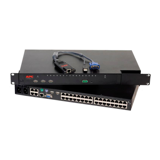
- Page 1 NetBAY Advanced Connectivity Technology Remote Console Manager Installer and User Guide For 32P1651, 1735-R16 and 32P1653...
- Page 2 INSTRUCTIONS This symbol is intended to alert the user to the presence of important operating and maintenance (servicing) instructions in the literature accompanying the appliance. DANGEROUS VOLTAGE This symbol is intended to alert the user to the presence of uninsulated dangerous voltage within the product’s enclosure that may be of sufficient magnitude to constitute a risk of electric shock to persons.
- Page 4 Statement 4: DANGER Electrical current from power, telephone, and communication cables is hazardous. To avoid a shock hazard: • Do not connect or disconnect any cables or perform installation, maintenance, or reconfiguration of this product during an electrical storm. • Connect all power cords to a properly wired and grounded electrical outlet.
- Page 5 Installer and User Guide...
-
Page 7: Table Of Contents
Table of Contents Chapter 1: Product Overview Features and Benefits ......3 Safety Precautions ......5 Chapter 2: Installation Getting Started . - Page 8 Product Overview Contents Features and Benefits ......3 Safety Precautions ......5...
-
Page 10: Chapter 1: Product Overview
No special software or drivers are required on the attached computers. Digital users access the RCM and all attached systems via Ethernet from a PC running the IBM NetBAY Virtual Console software (NetBAY VC). This software resides on the user’s PC only. User PCs can be located anywhere a valid network... - Page 11 RCM Installer and User Guide your data network, allowing access to your servers even if your applications network is down. Point and click control with NetBAY VC software The NetBAY VC software is a cross-platform management application that allows you to view and control the RCM and all attached servers. The NetBAY VC software provides secure authentication, data transfers and username/ password storage.
-
Page 12: Safety Precautions
To avoid potentially fatal shock hazard and possible damage to equipment, please observe the following precautions: • Do not use a 2-wire extension cord in any IBM product confi guration. - Page 13 RCM Installer and User Guide Test AC outlets at the computer and monitor for proper polarity and grounding. • • Use only with grounded outlets at both the computer and monitor. When using a backup uninterruptible power supply, power the computer, the monitor and the RCM off the supply.
- Page 14 Installation Contents Getting Started ....... . . 9 Installing Your RCM ......10 Cabling the RCM .
-
Page 16: Chapter 2: Installation
The RCM system uses IP addresses to uniquely identify the RCMs and the computers running NetBAY VC software. The RCM supports both BootP (a subset of DHCP) and static IP addressing. IBM recommends that IP addresses be reserved for each unit and that they remain static while the RCMs are... -
Page 17: Installing Your Rcm
RCM Installer and User Guide Installing Your RCM Your RCM ships with rack mounting brackets. Before installing the RCM and other components in the rack cabinet (if not already installed), stabilize the rack in a permanent location. Install your equipment starting at the bottom of the rack cabinet, then work to the top. - Page 18 Chapter 2: Installation Vertical installation in the side of a rack cabinet Line up the small holes of the L-shaped brackets with the screw holes in the switch. With a Phillips screwdriver, fasten the mounting brackets to the switch using two 8/32” x 1/2” pan head screws on each side. Mount the switch assembly to the rack by matching the long slots on each bracket to an appropriate set of holes on your equipment rack.
- Page 19 RCM Installer and User Guide Mount the switch assembly to the rack cabinet by matching the holes in the “short side” of each bracket to an appropriate set of matching holes on your rack cabinet. Next, insert the combination hex head screws through the slots in the bracket and the holes in the mounting rail, then into the cage nuts or clip nuts.
-
Page 20: Cabling The Rcm
Figure 2.3 illustrates one possible configuration for your RCM. Follow the detailed set of procedures following Figure 2.3 to successfully install your RCM. Remote Workstations Analog Port Network ARI Ports CAT 5 CAT 5 IBM NetBAY Switch Chained C2T Servers Server Server Server CAT 5 Server... - Page 21 RCM Installer and User Guide Statement 4: DANGER Electrical current from power, telephone, and communication cables is hazardous. To avoid a shock hazard: • Do not connect or disconnect any cables or perform installation, maintenance, or reconfiguration of this product during an electrical storm.
- Page 22 Chapter 2: Installation To confi gure the RCM hardware: You will see the Terminal Applications menu with six options. Select option 1, Network Confi guration. Figure 2.4: Network Configuration Menu Select option 1 to set your network speed. When possible, you should set your connection manually without relying on the auto negotiate feature.
- Page 23 RCM Installer and User Guide Set the pointer speed to Slow. Do this for any Windows NT user account that will be accessing the Windows NT system through the RCM. For Microsoft Windows 2000/Windows XP: From the desktop, select Start - Settings - Control Panel - Mouse. Click on the Motion tab.
- Page 24 Chapter 2: Installation When you reach the end of the chain, attach a terminator to the second RJ45 connector on the last KCO cable in the chain. To chain servers together using UCO cables: RCM or LCM (RCM shown) CAT 5 UCO Cable cable up to 10 meters...
- Page 25 RCM Installer and User Guide To connect a CCO cable to an IBM C2T server: Locate the CCO cables and CAT 5 cabling for your RCM. Attach one end of the CAT 5 cabling that will run from your CCO to the RCM to the RJ45 connector on the CCO cable.
- Page 26 Chapter 2: Installation Connect the other end of the CAT 5 cable to a port on the back of your RCM. Attach the keyboard, monitor and mouse connectors of the KCO cable to a user port on your cascade switch. Connect the servers to your cascade switch according to the switch manufacturer’s recommendations.
- Page 27 Workstation KCO Cable A KCO Cable B Second KCO connects to user port on the front of the switch IBM NetBAY 2x8 Switch Server 1 Server 2 Server 3 Figure 2.8: Cascaded Multi-user Legacy Switch Configuration To connect the network and turn on your RCM: Connect your network cable from the LAN port on the rear of the RCM to your network.
- Page 28 Chapter 2: Installation To use more than one language keyboard in a system: You can configure your remote console to synchronize with a target server if the keyboard of that server is set up for a different language than your remote console.
- Page 29 RCM Installer and User Guide...
- Page 30 Analog Port Operation Contents Controlling Your System at the Analog Port ..25 Viewing and Selecting Ports and Servers ... 25 Configuring OSCAR ......28 Viewing and Disconnecting Users .
-
Page 32: Chapter 3: Analog Port Operation
The RCM uses the On-Screen Configuration and Activity Reporting interface ® (OSCAR ) for IBM, which utilizes intuitive menus to configure your system and select computers. Viewing and Selecting Ports and Servers Use the OSCAR Main dialog box to view, configure and control servers in the RCM system. -
Page 33: Selecting Servers
RCM Installer and User Guide Viewing the status of your RCM system The status of the servers in your system are indicated in the right columns of the Main dialog box. The following table describes the status symbols. OSCAR Status Symbols Symbol Description KCO, UCO or CCO is online. -
Page 34: Soft Switching
Chapter 3: Analog Port Operation Soft switching Soft switching is the ability to switch servers using a hotkey sequence. You can soft switch to a server by pressing Print Screen and then typing the first few characters of its name or number. If you have a delay time set and you press the key sequences before that time has elapsed, OSCAR will not display. -
Page 35: Configuring Oscar
RCM Installer and User Guide OSCAR Navigation Basics (continued) This Keystroke Does This Print Screen, Backspace Toggles back to previous selection if no other keystrokes have been typed. Print Screen, Alt+Ø Immediately disengages user from a server; no server is selected. Status fl... -
Page 36: Assigning Server Names
Chapter 3: Analog Port Operation Figure 3.2: Setup Dialog Box Setup Features to Manage Routine Tasks for your Servers Feature Purpose Menu Change the server listing between numerically by port or eID number and alphabetically by name. Change the delay time before OSCAR displays after pressing Print Screen. Flag Change display, timing, color or location of the status fl... - Page 37 RCM Installer and User Guide Figure 3.3: Names Dialog Box NOTE: If the server list changes, the mouse cursor will turn into an hourglass as the list is automatically updated. No mouse or keyboard input will be accepted until the list update is complete. To assign names to servers: In the Names dialog box, select a server name or port number and click Modify.
-
Page 38: Assigning Device Types
Chapter 3: Analog Port Operation Assigning device types While the RCM automatically discovers cascade switches attached to your unit, you will need to specify the number of ports on the cascade switch through the Devices dialog box. The RCM recognizes KVM switches. You will see an Sw-8 appear in the Type category. -
Page 39: Changing The Display Behavior
RCM Installer and User Guide Figure 3.6: Device Modify Dialog Box Choose the number of ports supported by your switch and click OK. Repeat steps 1–3 for each port that needs a device type assigned. Click OK in the Devices dialog box to save settings. NOTE: Changes made in the Device Modify dialog box are not saved until you click OK in the Devices dialog box. -
Page 40: Controlling The Status Flag
Chapter 3: Analog Port Operation To choose the display order of servers in the Main dialog box: Select Name to display servers alphabetically by name. -or- Select eID to display servers numerically by eID number. -or- Select Port to display servers numerically by port number. Click OK. -
Page 41: Setting Console Security
RCM Installer and User Guide Figure 3.8: Flag Dialog Box To determine how the status fl ag is displayed: Select Name or eID to determine what information will be displayed. Select Displayed to show the fl ag all the time or select Timed to display the fl... - Page 42 Chapter 3: Analog Port Operation Use the Security dialog box to lock your console with password protection, set or change your password and enable the screen saver. NOTE: If a password has been previously set, you will have to enter the password before you can access the Security dialog box.
- Page 43 RCM Installer and User Guide ATTENTION: Monitor damage can result from the use of Energy mode with monitors not compliant with E NERGY (Optional) Click Test to activate the screen saver test which lasts 10 seconds then returns you to the Security dialog box. Click OK.
-
Page 44: Viewing And Disconnecting Users
Chapter 3: Analog Port Operation To exit the screen saver mode: Press any key or move your mouse. The Main dialog box appears. To turn off the screen saver: In the Security dialog box, clear Enable Screen Saver. Click OK. To immediately turn on the screen saver: Press Print Screen, then press Pause. -
Page 45: Running System Diagnostics
RCM Installer and User Guide Click OK to disconnect the user and return to the User Status dialog box. -or- Click X or press Escape to exit the dialog box without disconnecting a user. NOTE: If the User Status list has changed since it was last displayed, the mouse cursor will turn into an hourglass as the list is automatically updated. - Page 46 Chapter 3: Analog Port Operation To run diagnostic tests: If OSCAR is not open, press Print Screen. The Main dialog box will appear. Click Commands - Run Diagnostics. A warning message appears indicating that all users will be disconnected. Click OK to begin diagnostics. -or- Click X or press Escape to exit the dialog box without running a diagnostic test.
-
Page 47: Resetting Your Ps/2 Keyboard And Mouse
RCM Installer and User Guide Resetting Your PS/2 Keyboard and Mouse If your PS/2 keyboard or mouse stops responding, you may be able to re- establish operation of these peripherals by issuing a reset command. The reset command sends a key sequence to the server which causes the mouse and keyboard settings to be sent to the RCM. - Page 48 Chapter 3: Analog Port Operation Click Digital to view the Digitizer unit fi rmware versions. The Digital Version dialog box appears. The top section identifi es the Digitizer subsystem versions. The center section identifi es the current network settings. Click X or press Escape to return to the Version dialog box. Figure 3.16: Digital Version Dialog Box Click CO to view individual KCO, UCO and CCO cable version information.
-
Page 49: Scanning Your System
RCM Installer and User Guide Figure 3.18: CO Version Dialog Box Click X to close the Version dialog box. Scanning Your System In scan mode, the RCM automatically scans from port to port ( server to server). You can select up to 16 servers from a list of all servers attached to your unit. - Page 50 Chapter 3: Analog Port Operation Click the checkbox next to the servers you wish to scan. -or- Double-click on a server’s name or port. -or- Press Alt and the number of the server you wish to scan. You can select up to 16 servers.
-
Page 51: Broadcasting To Servers
RCM Installer and User Guide To cancel scan mode: Select a server if OSCAR is open. -or- Move the mouse or press any key on the keyboard if OSCAR is not open. Scanning will stop at the currently selected server. -or- Press Print Screen. - Page 52 Chapter 3: Analog Port Operation To broadcast to selected servers: From the Broadcast dialog box, select the mouse and keyboard checkboxes for the servers that are to receive the broadcast commands. -or- Press the Up or Down Arrow keys to move the cursor to the target server. Then press Alt+K to select the keyboard checkbox and/or Alt+M to select the mouse checkbox.
- Page 53 RCM Installer and User Guide...
- Page 54 Terminal Operations Contents Configuring the Terminal Menu ....49...
-
Page 56: Chapter 4: Terminal Operations
Chapter 4: Terminal Operations Chapter 4: Terminal Operations Each individual RCM can be configured at the unit level through the configuration port on the back of the unit. All Terminal commands are accessed through a terminal or PC running terminal emulation software. Configuring the Terminal Menu The RCM Terminal Applications menu features five selections: Network Configuration, Firmware Management, Enable Debug Messages, Set/Change... - Page 57 Firmware Management This menu option contains the FLASH Download command. The FLASH Download selection allows you to keep your RCM firmware current with upgrades available from IBM. For more information see Appendix A: FLASH Upgrades. Enable Debug Messages This menu option allows you to configure the RCM to display messages regarding the status of the RCM.
- Page 58 Appendices Contents Appendix A: FLASH Upgrades ....53 Appendix B: Technical Specifications ... . . 57 Appendix C: Hardware Maintenance Information .
-
Page 60: Appendices
Launch both the server software and the terminal emulation software. Verify that the RCM is turned on. After approximately 40 seconds, the RCM will send out a message, IBM RCM Ready__Press any key to continue. Press any key to access the main menu. The RCM main menu appears. - Page 61 RCM Installer and User Guide From the main menu, type 2 to select Firmware Management. The current version of your fi rmware displays on the Firmware Management menu. From the Firmware Management menu, type 1 to select FLASH Download. Type the name of the FLASH fi le and press Enter. 10.
- Page 62 Appendices Figure A.2: CO Upgrade Dialog Box The CO Upgrade dialog box appears. Click OK to initiate the upgrade and return to the CO Status dialog box. To upgrade CO fi rmware individually: Press Print Screen. The Main dialog box will appear. Click Commands - Display Versions.
- Page 63 RCM Installer and User Guide Figure A.4: CO Selection Dialog Box Select a KCO, UCO or CCO cable to upgrade and click the Version button. The CO Version dialog box appears. Figure A.5: CO Version Dialog Box Click the Load Firmware button. The Load dialog box appears. Figure A.6: CO Load Dialog Box Click OK to initiate the upgrade and return to the Status dialog box.
-
Page 64: Appendix B: Technical Specifications
Appendices Appendix B: Technical Specifications RCM Product Specifi cations Server Ports Number Types KCO, CCO, UCO intelligent cables Connectors RJ45 Sync Types Separate horizontal and vertical Plug and Play DDC2B Video Resolution Analog Port Maximum 1600 x 1280 @ 75 Hz Digital Port Maximum 1280 x 1024 @ 75 Hz Confi... -
Page 65: Appendix C: Hardware Maintenance Information
Field Replaceable Unit part numbers IBM FRU part numbers are subject to change without notice. The following table contains a listing of the FRU part numbers available at the time this document was published. -
Page 66: Appendix D: Notices
Web sites. The materials at those Web sites are not part of the materials for this IBM product, and use of those Web sites is at your own risk. - Page 67 IBM makes no representations or warranties with respect to non-IBM products. Support (if any) for the non-IBM products is provided by the third party, not IBM. Some software may differ from its retail version (if available), and may not include user...
-
Page 68: Appendix E: Electronic Emission Notices
Properly shielded and grounded cables and connectors must be used in order to meet FCC emission limits. Properly shielded and grounded cables and connectors must be used in order to meet FCC emission limits. IBM is not responsible for any radio or television interference caused by using other than recommended cables and connectors or by unauthorized changes or modifications to this equipment. -
Page 69: European Union Emc Directive Conformance Statement
This product is in conformity with the protection requirements of EU Council Directive 89/336/EEC on the approximation of the laws of the Member States relating to electro- magnetic compatibility. IBM cannot accept responsibility for any failure to satisfy the protection requirements resulting from a nonrecommended modification of the product, including the fitting of non-IBM option cards. - Page 71 59P2181 Rev.C 590245001B...
Need help?
Do you have a question about the 1735R16 and is the answer not in the manual?
Questions and answers