Table of Contents
Advertisement
Quick Links
Advertisement
Table of Contents

Subscribe to Our Youtube Channel
Related Manuals for Linak TECHLINE ELEVATE LC3 IC


Summary of Contents for Linak TECHLINE ELEVATE LC3 IC
- Page 1 ELEVATE ™ User Manual LINAK.COM/TECHLINE...
-
Page 2: Table Of Contents
ELEVATE™ User Manual | Contents Preface ������������������������������������������������������������������������������������������������������������������������������������������ 4 Terms of use ���������������������������������������������������������������������������������������������������������������������������������� 5 Introduction ����������������������������������������������������������������������������������������������������������������������������������� 6 Safety information ������������������������������������������������������������������������������������������������������������������������� 7 Warnings ��������������������������������������������������������������������������������������������������������������������������������������� 8 Recommendations ������������������������������������������������������������������������������������������������������������������������� 8 Features and options ���������������������������������������������������������������������������������������������������������������������� 9 Usage �������������������������������������������������������������������������������������������������������������������������������������������� 9 Technical specifications ���������������������������������������������������������������������������������������������������������������� 10 B10 data ��������������������������������������������������������������������������������������������������������������������������������� 10 Speed, load and current curves ����������������������������������������������������������������������������������������������������... - Page 3 ELEVATE™ User Manual | Declaration of Conformity ������������������������������������������������������������������������������������������������������������ 37 Contacts �������������������������������������������������������������������������������������������������������������������������������������� 39...
-
Page 4: Preface
This User Manual does not address the end user� It is intended as a source of information for the equipment or system manufacturer only, and it will tell you how to install, use and maintain your LINAK electronics� The manufacturer of the end product has the responsibility to provide a User Manual, where relevant safety information from this manual is passed on to the end user�... -
Page 5: Terms Of Use
LINAK, LINAK subsidiaries, or LINAK affiliates� All sales are subject to the ‘Standard Terms of Sale and Delivery for LINAK A/S’ available on LINAK websites� LINAK and the LINAK logotype are registered trademarks of LINAK A/S� All rights reserved�... -
Page 6: Introduction
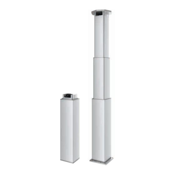
The LC3 IC can push or pull loads of up to 1,000 N with a speed of up to 100 mm/sec� The speed is adjustable and independent of the load� If higher loads are needed, please contact your local LINAK office�... -
Page 7: Safety Information
ELEVATE™ User Manual | Safety information Please read this safety information carefully� Be aware of the following three symbols throughout the user manual: Warning! Failing to follow these instructions can cause accidents resulting in serious personal injury� Recommendations Failing to follow these instructions can result in the product suffering damage or being ruined� Additional information Usage tips or additional information that is important in connection with the use of the product�... -
Page 8: Warnings
LC3 IC is heavy (more than 20 kg)� To avoid personal injury and product damage, DO NOT DROP! • Take special precautions concerning 3 party interfacing� If needed, please contact LINAK for further information� • Do not adjust anything during movement or while connected to mains, as it can cause personal injury�... -
Page 9: Features And Options
ELEVATE™ User Manual | Features and options • 24 V DC Brushless motor • 1,000 N load in push and pull • Max� speed 100 mm/sec� (adjustable and independent of load) • Stroke length from 400 mm to 1,100 mm in steps of 100 mm •... -
Page 10: Technical Specifications
Motor temp. [°C] Worm Gear temp. [°C] ELEVATE™ User Manual | 10 Brake temp. [°C] Run time [h] Technical specifications Observations LC3 IC with 24 V motor The columns only run until the temperature is stabilized, i.e. for 3 hours and do not run until failure. -
Page 11: Speed, Load And Current Curves
ELEVATE™ User Manual | 11 Speed, load and current curves LC3 IC 24 V - Speed vs Load 1000 1200 Load [N] LC3 IC 24 V - Current vs Load 1000 Load [N] Minor side load during extention* High side load during extention** * The cobot and the load is positioned around the centre of the column during extension�... -
Page 12: Ordering Example
ELEVATE™ User Manual | 12 Ordering example LC3 200 900 F700 0E 0730 8 2 3 1 C - 000 Type Spindle Pitch = 20 mm (1,000 N) = mm (in steps of 100 mm)� Stroke Length Min� 400 mm and max� 900 mm = 1,100 mm Option F600... -
Page 13: Installation
ELEVATE™ User Manual | 13 Installation Before mounting/dismounting the lifting column ensure that the following points are observed: • The lifting column is not in operation� • The lifting column is free from loads that could be released during this work� Before the lifting column is being put into operation, check the following: •... -
Page 14: Bending
ELEVATE™ User Manual | 14 Bending Bending moment - Static The maximal bending moment for static column use is 3000 Nm� Static column use is when the column is not moving and e�g� the cobot creates a bending moment� High off-centre loads apply bending moments onto the lifting column and cause bending of the column� The following graph shows the expected bending for different bending moments (MB, MT) and strokes�... - Page 15 ELEVATE™ User Manual | 15 Bending with bending moment M ELEVATE 900mm at 400 Nm after 135 km ELEVATE 900mm at 800 Nm after 135 km ELEVATE 900mm at 1200 Nm after 135 km ELEVATE 900mm at 400 Nm after 0,1 km ELEVATE 900mm at 800 Nm after 0,1 km ELEVATE 900mm at 1200 Nm after 0,1 km ELEVATE 1100mm at 400 Nm after 0,1 km...
- Page 16 ELEVATE™ User Manual | 16 Bending moment - Dynamic The maximal bending moment for dynamic column use is 1,400 Nm� This value must not be exceeded while the column is running in or out� In general, it is recommended to retract or partially retract the cobot while the column is running�...
-
Page 17: Built-In Dimensions
ELEVATE™ User Manual | 17 Built-in dimensions The ELEVATE options with a stroke of 700 mm, 900 mm and 1,100 mm come with 8 M8 mounting holes ™ on the outer profile� All other options come without these holes� See chapter “Mounting of tools on the side of an LC3 IC”... - Page 18 ELEVATE™ User Manual | 18 Use 4 pcs� M10 8�8 bolts at each end of the column for mounting to the application� The screw depth must be min� 20 mm and max� 30 mm in the aluminium profile� Screw torque: 35 Nm� Drawing No.: TEC-0001888 SCALE : 1:5 EP = STANDARD-SBU...
-
Page 19: Accessories
LC3 IC� There are different accessories available to simplify the integration ™ with compatible cobot brands� Plug-in software is freely available on LINAK�com� Cable set The set includes a 5 m power cable, a 5 m signal cable, and a cable lock with a mounting screw� The cable set is required for the electrical installation of an LC3 IC�... -
Page 20: Base Plate
No.: Bottom Plate Elevate ELEVATE_BASEPLATE-A Confidential: Property of LINAK A/S GROUP HEADQUARTER, DK-6430 NORDBORG, DENMARK Phone +45 73 15 15 15 ; FAX +45 74 45 80 48. Not to be handed over to, copied or used by third party. -
Page 21: Top Plate Doosan Tm
DOOSAN-A Confidential: Property of LINAK A/S GROUP HEADQUARTER, DK-6430 NORDBORG, DENMARK Phone +45 73 15 15 15 ; FAX +45 74 45 80 48. Not to be handed over to, copied or used by third party. The aluminium plate comes with 2 additional M6 x 1�0 holes to mount an energy chain� Drawings can be... -
Page 22: Available Kits
ELEVATE™ User Manual | 22 Available kits The following accessory kits are available: Cable set Article number: 1002W8165 Description Quantity Power cable, 5 m, 6-pin minifit Signal cable, 5 m, 9-pin microfit Cable lock with mounting screw T15 ELEVATE Cobot kit ™... -
Page 23: Elevate Kit Ur
ELEVATE™ User Manual | 23 ELEVATE Kit UR Article number: 1002W8163 Description Quantity Power cable, 5 m, 6-pin minifit Signal cable, 5 m, 9-pin microfit Cable lock with mounting screw T15 Base screw M10 x 45 A2 ISO 10462 Base plate Top screw M10 x 80 A2 ISO 10642 Top plate UR LC3 IC Mounting kit... -
Page 24: Electrical Installation
The ethernet cable is not supplied by LINAK� When the power cable and signal cable are connected to the lifting column, the cable relief can be used to secure both cables to the lifting column�... -
Page 25: Elevate ™ Easy
ELEVATE™ User Manual | 25 ELEVATE Easy ™ Connection diagram Platform: B3 BROWN 24 V DC BLUE INWARDS BLACK OUTWARDS YELLOW GREEN INPUT/OUTPUT Power Cable Signal Cable Flying Leads Flying Leads (Molex mini-fit 12-pin) Please be aware that if the power supply is not properly connected, you might damage the column! -
Page 26: Specification
ELEVATE™ User Manual | 26 ELEVATE Easy ™ I/O specifications Input/Output Specification Comments Easy-to-use interface with integrated power electronics� Description 24 V DC + (VCC) Note: Brown Connect Brown to positive Do not change the power supply polarity 24 V ± 10 %, motor current limit: 25 A on the Brown and Blue wires! Power supply GND (-) is electrically 24 V DC - (GND) -
Page 27: Wiring Example Elevate
URCap on the teach pendant� ELEVATE does not come with safety relay/contactors nor power supply� The wiring diagram only shows a suggestion to integrate ELEVATE into a safe torque off system� Download the ELEVATE URCap from LINAK�com and get more information� URCap wiring diagram for ELEVATE Easy... -
Page 28: Elevate ™ Pro
ELEVATE™ User Manual | 28 ELEVATE ™ Connection diagram Platform: C3 BROWN 24 V DC BLUE BLACK 4-20 mA PROPORTIONAL Hall A Dual Hall YELLOW Hall B GREEN Power Cable Signal Cable Diagram of Dual Hall: Flying Leads Flying Leads (Molex mini-fit 12-pin) Please be aware that if the power supply is not properly connected, you might damage the column! - Page 29 ELEVATE™ User Manual | 29 ELEVATE ™ I/O specifications Input/Output Specification Comments Easy-to-use interface with integrated power electronics� The column is speed-controlled by means Description of a 4-20 mA signal� Proportional provides a wide range of possibilities for customisation� 24 V DC + (VCC) Note: Do not change the power supply Brown Connect Brown to positive...
-
Page 30: Wiring Example Elevate
UR controller before the power is gone� If a 500 ms delay is not implemented, a re-initialization in the program is recommended to keep the position accuracy� Download the ELEVATE URCap from LINAK�com and get more information� URCap wiring diagram for ELEVATE Pro... - Page 31 ELEVATE™ User Manual | 31 ELEVATE ™ I/O specifications The speed control over the analogue 4-20 mA is started when the signal is set between 11-13 mA for 100 ms� After this initialization the full signal width can be used to control the speed (see graphic below)� In case the analogue signal exceeds 19�5 mA or the signal falls below 4�5 mA, the column will stop and go into an error mode�...
-
Page 32: Elevate ™ Modbus Tcp/Ip
ELEVATE™ User Manual | 32 ELEVATE Modbus TCP/IP ™ Connection diagram Platform: 0E BROWN 24V DC BLUE Run In BLACK Run Out Signal Signal Split Power Supply ORANGE Communi- Ethernet RJ45 cation Ethernet RJ45 Power Cable Signal Cable Ethernet Flying Leads Flying Leads (Molex mini-fit 12-pin) Please be aware that if the power supply is not properly connected, you might damage the column! - Page 33 ELEVATE™ User Manual | 33 ELEVATE Modbus TCP/IP ™ I/O Specifications Input/Output Specification Comments Easy-to-use interface with integrated power electronics� Uses Modbus TCP/IP messages to Description command movement, setting parameters and to deliver feedback form the lifting column 24 V DC + (VCC) Note: Brown Connect Brown to positive...
- Page 34 The wiring diagram only shows a suggestion to integrate ELEVATE into a safe torque off system� Download the ELEVATE components for TMFlow from LINAK�com and get more information� Ethernet Omron wiring diagram for ELEVATE Modbus...
- Page 35 The wiring diagram only shows a suggestion to integrate ELEVATE into a safe torque off system� Download the ELEVATE Cbun from LINAK�com and get more information� Kassow wiring diagram for ELEVATE Modbus LC3 IC pinout...
-
Page 36: Mounting Of Tools On The Side Of An Lc3 Ic
ELEVATE™ User Manual | 36 Mounting of tools on the side of an LC3 IC SECTION A-A It is possible to mount tools on all 4 sides of the LC3 IC at the same time� However, it requires that the holes for mounting are placed with different distances from the top and/or bottom plate�... -
Page 37: Declaration Of Conformity
ELEVATE™ User Manual | 37 Declaration of Conformity DECLARATION OF CONFORMITY LINAK A/S Smedevænget 8 DK - 6430 Nordborg Hereby declares that LINAK Lifting Column: LC3******F***2H*****C3**-000 LC3******F***3H*****C3**-000 LC3******F***4H*****C3**-000 LC3******F***5H*****C3**-000 LC3******F***6H*****C3**-000 (The * in the product description can either be a character or a number, thereby defining the variation of the product) - Page 38 DECLARATION OF CONFORMITY LINAK A/S Smedevænget 8 DK - 6430 Nordborg Hereby declares that LINAK Lifting Column: LC3******F***00*****23**-*F* LC3******F***00*****23**-*G* LC3******F***00*****23**-*H* (The * in the product description can either be a character or a number, thereby defining the variation of the product)
- Page 39 LINAK, LINAK subsidiaries, or LINAK affiliates. the same reason, LINAK cannot guarantee the correctness and actual status of imprinted information on All sales are subject to the ‘Standard Terms of Sale and Delivery for LINAK A/S’ available on LINAK websites. its products.
Need help?
Do you have a question about the TECHLINE ELEVATE LC3 IC and is the answer not in the manual?
Questions and answers