Linak MEDLINE CARELINE BL1 User Manual
Hide thumbs
Also See for MEDLINE CARELINE BL1:
- User manual (192 pages) ,
- User manual (295 pages) ,
- User manual (131 pages)
Table of Contents
Advertisement
Quick Links
Advertisement
Table of Contents
Troubleshooting

Related Manuals for Linak MEDLINE CARELINE BL1


Summary of Contents for Linak MEDLINE CARELINE BL1
- Page 1 Lifting Columns User Manual LINAK.COM/MEDLINE-CARELINE...
-
Page 2: Table Of Contents
IPX6 Washable ������������������������������������������������������������������������������������������������������������������������ 25 Rinsing aids ����������������������������������������������������������������������������������������������������������������������������� 26 IPX6 Washable DURA™ ����������������������������������������������������������������������������������������������������������� 27 Cable wash ����������������������������������������������������������������������������������������������������������������������������� 28 General maintenance ........................ 29 Maintenance of all LINAK lifting columns ��������������������������������������������������������������������������������� 29 Repair and disposal ........................30 Troubleshooting ........................31 BL1 .............................. 32 LC1 ............................. 39 LC3 .............................. -
Page 3: Preface
This User Manual does not address the end user� It is intended as a source of information for the equipment or system manufacturer only, and it will tell you how to install, use and maintain your LINAK product/system� The manufacturer of the end product has the responsibility to provide a User Manual where relevant safety information from this manual is passed on to the end user�... -
Page 4: Declaration Of Incorporation Of Partly Completed Machinery
DECLARATION OF INCORPORATION OF PARTLY COMPLETED MACHINERY LINAK A/S Smedevænget 8 DK - 6430 Nordborg LINAK DESKLINE ® LINAK A/S hereby declares that products, characterised by the following models and types: Control Boxes CBD6S Linear Actuators DB5, DB6, DB14, LA23, LA31 Lifting Columns... -
Page 5: Important Information
Persons who do not have the necessary experience or knowledge of LINAK products should not use these� Moreover, persons with reduced physical or mental abilities must not use the products, unless they are under surveillance or they have been thoroughly instructed in the use of the equipment by a person who is responsible for the safety of these persons�... -
Page 6: General Warnings
Do not use chemicals� Inspect the actuator system regularly for damage and wear� Do not expose LINAK actuator system components to high intensity ultraviolet radiation disinfection lamps� This may damage the enclosure, supporting parts and cables� LINAK actuators and electronics are not designed for use within the following fields: •... - Page 7 Lifting Columns | A LINAK control box, actuator and accessory component must, in the final application, be placed where it is not exposed to any impact� This is to prevent damage if a passer-by accidentally hits it with an object or when cleaning the floor with a broom or a mop� On a medical bed e�g� this might be underneath the mattress support platform�...
- Page 8 Lifting Columns | Be aware that during the design of medical devices, the risk of personal injury (for instance squeezing of fingers or arms) must be minimised� If irregularities are observed, the actuator must be replaced� All cables must be mounted in such a way that they are not trapped or exposed to tension or sharp objects when the application is moved in different directions�...
-
Page 9: General Recommendations
- Do not sideload the actuator� - Do not step on or kick any LINAK component� When the equipment is not in use: - Switch off the mains supply or pull out the plug in order to prevent unintentional operation�... -
Page 10: General Warranty Periods
Batteries are covered by a specific product warranty of 12 months� External products that are not manufactured by LINAK A/S: 12 months are added to the warranty period, for instance for transportation and stocking� Relabelling of these products only takes place, if the production date exceeds one year from the date of dispatch to the customer�... -
Page 11: Electromagnetic Compatibility (Emc)
2014/30/EU� The systems are designed to meet all requirements of applicable standards and have been tested to meet IEC 60601-1-2 requirements� Emission: LINAK Actuator Systems are CISPR 11, Group 1, Class B products, comply with IEC 61000-3-2, Class A and IEC 61000-3-3 unless stated otherwise in the relevant section of this document� Immunity: Test levels are according to Professional Healthcare Facility and Home Healthcare Facility Environment�... -
Page 12: Electrostatic Discharge (Esd)
ESD� • LINAK can only guarantee the lifetime of ESDS devices if they are handled in the same way from production at LINAK A/S until they are mounted in the manufacturer’s application� It is therefore important that the ESDS devices are not removed from the ESD protected packaging before they are physically within the EPA area at the customer premises�... -
Page 13: Rf Transmitter/Receiver Properties
Lifting Columns | 13 RF transmitter/receiver properties Some LINAK products emit RF-power by intention for communication purposes� Frequency band of transmission: 2402 MHz - 2480 MHz Type: BLUETOOTH Low Energy BLE 4�2 ® Modulation: GFSK Maximum Effective Radiated Power (ERP): 10 dBm FCC and IC Statements For RF-emitting products (e�g�... -
Page 14: Symbols
Lifting Columns | 14 Symbols The following symbols are used on the LINAK product labels, where applicable: IEC 60417-5172: Compliance to all relevant EC directives Class II equipment IEC 60417-5840: UK Conformity Assessment Applied part type B IEC 60417-5019: Regulatory compliance mark:... - Page 15 Lifting Columns | 15 Electrical Testing Laboratories (ETL) marking Due to space limitations, the complete ETL marking demands are not represented on the marking plates� The full ETL recognised component markings are shown here: C/N 120690 C/N 4008004 C/N 4008838 Conforms to ANSI/AAMI Std.
-
Page 16: Batteries
Do not use or store LINAK battery packs in places where the ambient temperature exceeds 50 °C, such as inside a hot automobile, in direct sunlight, or in front of a stove or a source of intense heat�... -
Page 17: Lithium Ion Batteries
LINAK explicitly disclaims lost profits, failure to realise expected savings, any claim against our customers by a third party, or any other commercial or economic losses of any kind, even if LINAK has been advised of the possibility of such damages or losses�... - Page 18 Mounting instructions must be followed in order to avoid exposing batteries to water� In general, recharging of battery must take place every 6 months� However, please note: - New Li-Ion batteries, shipped from LINAK are in a deep-sleep state, where the self-discharge is very little...
- Page 19 Allow the battery to settle to room temperature before use� Lithium ion batteries are not intended for use in outdoor applications and indoor pool environments� If the battery is completely discharged, then recharge the battery before storage� Always use correct LINAK charger DO NOT: Heat or burn the batteries�...
-
Page 20: Lead Acid Batteries
(silicone ring or joint filler) is not damaged and that it is correctly placed in the groove� Hereafter, the screws in the cover are to be fastened with approx� 1 Nm� If necessary, replacement sealing is available at LINAK� The battery compartment is supplied with ventilation that ensures correct and necessary airing of the battery compartment�... -
Page 21: System Description
Connect the different actuators to the different channels on the control box� Each channel is marked with a number (e�g� “1”, “2”, “3”……�)� Check that all plugs are well connected and firmly pushed into the connector� Due to the fact that LINAK® control boxes are designed for a high IP degree, a firm force can be required�... -
Page 22: General Environmental Conditions
If the actuator is assembled in the application and is exposed to push or pull during transportation, the actuator can be damaged� Do not drop a LINAK component or otherwise damage the housing during disassembly or transportation� We do not recommend to use a LINAK component that has been damaged�... -
Page 23: Information On Start-Up, Deinstallation And Operation
• The actuator/lifting column system may only be used in an environment corresponding to the IP rating of the system� LINAK products are marked with the actual IP rating on the label� • If any individual parts are suspected to be damaged, do not install the parts, but return them for inspection/service�... -
Page 24: Cleaning
Lifting Columns | 24 Cleaning The products can be cleaned as described in the following according to their IP protection stated on the product label� The IP code specifies the protection degree provided by the enclosures� For most products, only the protection against ingress of water (second characteristic numeral) is specified, ingress of solid foreign objects or dust (first characteristic numeral) is not specified and therefore replaced by the letter X in the code�... -
Page 25: Ipx6 Washable
Dekotaminationsanlagen)� Description: At LINAK, the washing test takes place in an instrument washing machine, which is fitted and programmed in such a way that it duplicates the process used in a typical hospital installation for the cleaning of beds and other medical equipment�... -
Page 26: Rinsing Aids
• They must not contain caustic solutions • They must not change the surface structure or adhesive properties of the plastic • Must not break down grease LINAK washing profile according to LINAK washing machine IEC 60601-2-52 °C 70.0 65.0 60.0... -
Page 27: Ipx6 Washable Dura
IPX6 Washable DURA™ Description of washing test LINAK washable products frequently go through a fully controlled washing test� The LINAK term “IPX6 Washable DURA” signifies that the products conform exclusively to this test� The “IPX6 Washable DURA” washing test is used to ensure that products that are rated “IPX6 Washable DURA”... -
Page 28: Cable Wash
Lifting Columns | 28 LINAK washing profile for the “IPX6 Washable DURA” process LINAK washing profile according to LINAK washing machine DURA (Note: The temperature is measured at the unit) Cable wash Before the washing procedure starts In order to maintain the flexibility of the cables, it is important that the cable is placed in such a way that the cable’s own weight does not strain the coil... -
Page 29: General Maintenance
• LINAK products must be IPX6 Washable and IPX6 Washable DURA when cleaning in wash tunnels • O-rings: When individual parts are replaced in a LINAK IPX6, IPX6 Washable or IPX6 Washable DURA system, the O-rings must be replaced at the same time on all parts� On all products where replaceable cables or fuses have been dismounted or replaced, the O-ring must be replaced, and the O-rings and the receptacle insert must be greased with an acid-free Vaseline�... -
Page 30: Repair And Disposal
LINAK service centre� In order to avoid the risk of malfunction, all actuator repairs must only be carried out by an authorised LINAK Service shop or repairers, as special tools and parts must be used�... -
Page 31: Troubleshooting
Lifting Columns | 31 Troubleshooting Symptom Possible cause Action - The actuator is not connnected to - Connect the actuator to the the control box control box No motor sound or movement of piston rod - Blown fuse in the control box - Fuse must be changed - Cable damaged - Send actuator for repair... -
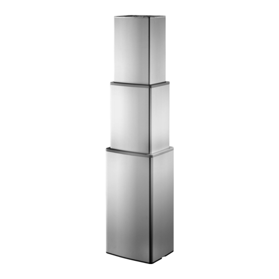
Page 32: Bl1
Lifting Columns | 32 The BL1 is a 3-part lifting column designed to be used for example in hospital beds, nursing home beds, treatment chairs, couches and dental chairs� The lifting column is compact and has a long stroke length� The 3-part guidance enables an overlap between the individual profiles, which ensures a high degree of stability�... - Page 33 • Do not loosen any screws on the BL1, this can cause collapse of the column • LINAK recommends making regular measurement of Class 1 protective ground conductivity in the application to avoid a disconnected grounding cable� Worn out or defect parts must be replaced�...
- Page 34 Lifting Columns | 34 BL1 end plate kit with cable through Top plate dimensions: Bottom plate dimensions: Motor cable Hand control cable Hand control cable Please notice the thickness of the bottom plate is 12 mm� The thickness of the bottom plate without connections is 10 mm� Bottom plate dimensions: Motor cable Drawing no�: 0801263-A...
- Page 35 Lifting Columns | 35 BL1 mounting guidelines • BL1 is for use in push applications, and can be mounted in both directions (smallest profile down, or up)� Note: The cable outlet can be positioned at the top (smallest profile)� If the option with integrated cable is chosen, the cable outlet can also be positioned at the bottom (biggest profile)�...
- Page 36 Lifting Columns | 36 Drawing no�: 0807000-1 Mounting of BL1 with cable through: Mounting holes Mounting holes Drain hole Drain hole Mounting holes Mounting holes Drawing no�: 0807001-1...
- Page 37 • Remember to secure the cable mounted in the top of the column to the application, so that it cannot be pulled out of the column� We recommend to use LINAK Cable: - Lock kit for BL1 with motor cable: 0808040 - Lock kit for BL1 with hand control cable through: 0808046 Use only the screws included in the kit�...
- Page 38 Lifting Columns | 38 When mounting more than one BL1 you need to consider the fixation: Fixed pivot point Moveable pivot point Example 1� Fixed pivot point Fixed pivot point Example 2� The reason why it is important only to fix one column, is that the columns will not move exactly in parallel – even if you have positioning such as hall�...
-
Page 39: Lc1
Operating temperature: + 5 °C to + 40 °C Storage temperature: 10 °C to +50 °C Compatibility: Compatible with LINAK or customer-own control boxes� Please contact LINAK for further information� Relative humidity: 20% - 80%, non-condensing Atmospheric pressure: 700 to 1060 hPa Meters above sea level: Max�... - Page 40 Lifting Columns | 40 Mounting guidelines LC1 is for use in push applications to obtain IPX6� The mounting direction must be with the largest profile down� It is very simple to mount the LC1 in the application using selftapping screws in the mounting holes of both endplates�...
- Page 41 Customer production of top and/or bottom mounting plates: LINAK can forward a 3D drawing with dimensions that comply with the customer choice of cables/plugs� If the customer uses own top plate design, remember to make a drainage hole to drain water from the area...
- Page 42 Lifting Columns | 42 Mounting screws For the safety factor and off-centre load specifications to be valid, the correct mounting screws must be used� The thread engagement length needs to be minimum 30 mm (into the aluminium profile)� Recommended screw torque is 20 Nm ±10%� Screw length for LC1-R: max�...
- Page 43 Lifting Columns | 43 Mounting bracket for LC1-D profile The mounting bracket can for instance be used for placement of an extra actuator, customised cover for encapsulation, control box, computer etc� Mounting bracket order number: 0578006 Mounting brackets only possible on 3 sides:...
- Page 44 Lifting Columns | 44 Bracket dimensions Figure 1 Mounting bracket dimensions (mm) Figure 2 Mounting bracket assembled...
- Page 45 Lifting Columns | 45 Mounting guideline for two LC1 columns in application When mounting more than one LC1 you need to consider the fixation: The reason why it is important only to fix one column is that the columns will not move exactly in parallel – even if you have positioning such as Hall�...
- Page 46 RELEASED: • Always use LINAK compatible components and ensure that the application functionality is tested with all accessories connected before bringing it into service� • The mounting plate in the application must cover the entire LC1 top plate and be strong enough to carry the load�...
- Page 47 • LINAK recommends to make regular measurements of Class 1 protective ground conductivity in the application to avoid a disconnected grounding cable� If there are worn-out or defective parts, the complete LC1 column must be replaced�...
-
Page 48: Lc3
+ 5 °C to + 40 °C Storage temperature: -10 °C to +50 °C Compatibility: Compatible with LINAK control boxes� ® Please contact LINAK for further information� Relative humidity: 20% to 80%, non-condensing Atmospheric pressure: 700 to 1060 hPa Meters above sea level: Max� 3000 meters... - Page 49 Lifting Columns | 49 If you want to use the column with a high off-center load, we recommend that you install the weight in one of the 3 ways illustrated by the green symbols� It is not recommended to install the weight on the opposite side of the mechanical endstop as illustrated with the red symbol�...
- Page 50 Lifting Columns | 50 LC3 3-Stage ·◄ � - --------------------------- � � v'?h 15 mm distance 3 mm distance � '◄ to thread to thread Screw depth min� 20 mm Mounting holes, top Mounting holes, bottom � ...lm, � (M4l 142 -146 Drill-Max.
- Page 51 Remember to secure the cable mounted in the top of the column to the application, so that it cannot be pulled out of the column� We recommend to use LINAK Cable: • Lock kit for minifit cable: 1002W8136-A� • Lock kit for hand control cable through: 1002W8137-A Use only the screws included in the kit�...
- Page 52 Lifting Columns | 52 Cable connections overview 3-stage is used as examples but variants are also applicable for 2-stage� This overview shows all possible cable connections, but please notice that some variants are upon request� Variant Top plate Side entry Model view Drawing no.:1002W9005 Drawing no.:1002W9005...
- Page 53 Lifting Columns | 53 Variant Top plate Side entry Model view Drawing no.:1002W9005 Drawing no.:1002W9005 T200 Connections 5: Motor 6: HB through 3: HB through T030 Connections 5: Motor 6: Mains through 1-2 pin 3: Mains through 1-2 pin T040 Connections 5: Motor 6: Mains through 2-2 pin...
- Page 54 Lifting Columns | 54 Variant Top plate Side entry Model view Drawing no.:1002W9005 Drawing no.:1002W9005 T101 Connections 5: Motor Including protective grounding cable 6: Minifit through 3: Minifit through T201 Connections 5: Motor Including protective grounding cable 6: HB through 3: HB through T031 Connections...
- Page 55 Lifting Columns | 55 Variant Top plate Side entry Model view Drawing no.:1002W9005 Drawing no.:1002W9005 T041 Connections 5: Motor Including protective grounding cable 6: Mains through 2-2 pin 3: Mains through 2-2 pin T110 Connections 5: Motor 6: Minifit through (top) 3: Minifit through (side) 7: Minifit through (top) 4: Minifit through (side)
- Page 56 Lifting Columns | 56 Variant Top plate Side entry Model view Drawing no.:1002W9005 Drawing no.:1002W9005 T220 Connections 5: Motor 6: HB through (top) 3: HB through (side) 7: HB through (top) 4: HB through (side) T130 Connections 5: Motor 6: Mains through 1-2 pin 3: Mains through 1-2 pin 7: Minifit through 4: Minifit through...
- Page 57 Lifting Columns | 57 Variant Top plate Side entry Model view Drawing no.:1002W9005 Drawing no.:1002W9005 T230 Connections 5: Motor 6: Mains through 1-2 pin 3: Mains through 1-2 pin 7: HB through 4: HB through T240 Connections 5: Motor 6: Mains through 2-2 pin 3: Mains through 2-2 pin 7: HB through 4: HB through...
- Page 58 Lifting Columns | 58 Variant Top plate Side entry Model view Drawing no.:1002W9005 Drawing no.:1002W9005 S400 Connections 3: Motor supply S500 Connections 3: Motor supply S301 Connections 3: Motor supply Including protective grounding cable...
- Page 59 Lifting Columns | 59 Variant Top plate Side entry Model view Drawing no.:1002W9005 Drawing no.:1002W9005 S401 Connections 3: Motor supply Including protective grounding cable S501 Connections 3: Motor supply Including protective grounding cable S310 Connections 3: Motor supply 6: Minifit through 4: Minifit through...
- Page 60 Lifting Columns | 60 Variant Top plate Side entry Model view Drawing no.:1002W9005 Drawing no.:1002W9005 S320 Connections 3: Motor supply 6: HB through 4: HB through S410 Connections 3: Motor supply 6: Minifit through 4: Minifit through S420 Connections 3: Motor supply 6: HB through 4: HB through...
- Page 61 Lifting Columns | 61 Variant Top plate Side entry Model view Drawing no.:1002W9005 Drawing no.:1002W9005 S510 Connections 3: Motor supply 6: Minifit through 4: Minifit through S520 Connections 3: Motor supply 6: HB through 4: HB through S330 Connections 6: Mains through 1-2 pin 3: Mains through 1-2 pin 4: Motor...
- Page 62 Lifting Columns | 62 Variant Top plate Side entry Model view Drawing no.:1002W9005 Drawing no.:1002W9005 S340 Connections 6: Mains through 2-2 pin 3: Mains through 2-2 pin 4: Motor S430 Connections 6: Mains through 1-2 pin 3: Mains through 1-2 pin 4: Motor S440 Connections...
- Page 63 Lifting Columns | 63 Variant Top plate Side entry Model view Drawing no.:1002W9005 Drawing no.:1002W9005 S530 Connections 6: Mains through 1-2 pin 3: Mains through 1-2 pin 4: Motor S540 Connections 6: Mains through 2-2 pin 3: Mains through 2-2 pin 4: Motor T051 Connections...
- Page 64 Lifting Columns | 64 Variant Top plate Side entry Model view Drawing no.:1002W9005 Drawing no.:1002W9005 T061 Connections 5: Motor 6: Mains through 2-3 pin 3: Mains through 2-3 pin with earth Mounting of a product on the side of an LC3 It is possible to mount a product on all 4 sides of the LC3 at the same time�...
- Page 65 Lifting Columns | 65 When mounting more than one LC3 you need to consider the fixation: The reason why it is important only to fix one column, is that the columns will not move exactly in parallel – even if you have positioning such as hall� If more than one column is fixed it can lead to dangerous situations�...
- Page 66 Lifting Columns | 66 Feedback specifications: Potentiometer Ordering code no.: 0P Feedback specification VCC max� 15 V Potentiometer total resistance 10 kΩ ± 20% Non-linearity ±2% Hysteresis ±2% Calculation of output vs. SL/pitch Notice: Only one gearing available for stroke length variants up to 700 mm The output ratio of a potentiometer for a given position is defined as: where SL is the actual position in millimeters on the stroke length (SL), relative to end-stop inwards�...
- Page 67 Lifting Columns | 67 Input/output specifications: dual Hall positioning Dual Hall digital (F3) with power switch Item Specification Comment Pin1 configuration Pin2 Pin3 Pin4 HALL A Pin5 HALL B Pin6 4-15V Current Maximum 15mA @10kΩ and 1nF load� See diagram� HALL A/B TState is minimum 5ms in all states Signal pattern during movement:...
- Page 68 Lifting Columns | 68 Potentiometer Potentiometer cables Columns with Potentiometer feedback option require specific actuator cables, both for termination through top-plate (option Txxx) and through side-entry (option Sxxx)� Table 1, connection to the motor and to the potentiometer and their colour� Colour Colour E1 (power switch) F6...
- Page 69 • LINAK recommend using a safety nut in medical applications! LC3 has safety nut as standard� • Do not loosen any screws on the LC3, this can cause collapse of the column! •...
-
Page 70: Contacts
LINAK, LINAK subsidiaries, or LINAK affiliates. the same reason, LINAK cannot guarantee the correctness and actual status of imprinted information on All sales are subject to the ‘Standard Terms of Sale and Delivery for LINAK A/S’ available on LINAK its products.
Need help?
Do you have a question about the MEDLINE CARELINE BL1 and is the answer not in the manual?
Questions and answers