
Subscribe to Our Youtube Channel
Related Manuals for Omtech POLAR+


Summary of Contents for Omtech POLAR+
- Page 1 V20240904 POLAR+ | 55W | CO Desktop Laser Engraver User Manual Read Carefully Before Use Keep for Future Reference...
- Page 2 However, constantly running your laser above 70% of its rated power can significantly shorten its service life. Read this manual before use, keep it for future reference, contact OMTech customer service if any point is unclear, and provide it with the machine if it is ever given or sold to another person.
- Page 3 Welcome to the OMTech Community! For helpful hints and instructional videos, visit our Help Center or join our official laser group! If you encounter any issues with your engraver, please feel free to contact us. Our support team will respond within 24 hours to resolve your concerns.
-
Page 4: Table Of Contents
Contents 1 Safety Information .................... 1 Disclaimer ..............................1 Symbol Guide ............................. 2 General Safety Instructions ........................3 1.4 Laser Safety Instructions ......................... 4 Electrical Safety Instructions ........................5 1.6 Material Safety Instructions ........................6 Disposal Safety Instructions ........................8 2 Introduction ...................... - Page 5 5.4 Air Assist ..............................50 6 Operation ......................51 6.1 Operation Overview ..........................51 6.2 General Operation ............................. 52 6.2.1 Preparing Your Material ......................52 6.2.2 Turning on Your Engraver ......................57 6.2.3 Loading Your Design ........................58 6.2.4 Adjusting the Software's Parameters ..................60 6.2.5 Autofocusing Your Laser ......................
- Page 6 Content 8 Troubleshooting ....................88 Connection ..............................88 8.1.1 The Engraver Can't Find the Device Through Ethernet Cable ......... 88 8.1.2 The Engraver Can't Find the Device Through Wi-Fi ............89 8.1.3 The Engraver Can't Find Device Through USB ..............90 8.2 Hardware ..............................
-
Page 8: Safety Information
Read this disclaimer completely and carefully before proceeding with the rest of the manual content. As-Is This OMTech product is sold ‘as is’ and without any express or implied warranties, including but not limited to the implied warranties of merchantability and fitness for a particular purpose. -
Page 9: Symbol Guide
1.2 Symbol Guide The following symbols are used on this machine’s labeling or in this manual: These items present a risk of serious property damage or personal injury. These items address similarly serious concerns about the laser beam. These items address similarly serious concerns about electrical components. These items address similarly serious concerns about fire hazards. -
Page 10: General Safety Instructions
1 Safety Information 1.3 General Safety Instructions • Your engraver should come with instruction labels in the following locations. If any of these labels is missing, illegible, or damaged, it must be replaced. • Use this laser engraving engraver only in accordance with all applicable local and national laws and regulations. -
Page 11: Laser Safety Instructions
• DO NOT operate this engraver with its cooling liquid hotter than 104 ℉ (40 ℃ ). If this temperature is ever approached, stop using the laser but allow the exhaust and water-cooling systems to continue running to clear and cool the machine. •... -
Page 12: Electrical Safety Instructions
1 Safety Information • NEVER leave any part of the engraver open during operation except (when needed) the pass- through doors. Never interfere with the laser beam, do not place any part of your body in any part of the laser path during operation, and never attempt to view the laser directly. When using the pass-through doors or otherwise risking exposure to the laser beam, take measures to protect yourself from potentially reflected laser beams including the use of personal protective equipment such as protective eyewear specially designed to filter the specific wavelength of... -
Page 13: Material Safety Instructions
• DO NOT use standard surge protectors, extension cords, or power strips. Only use additional wiring thick enough to safely handle the full load of the machine.Use only surge protectors rated over 2000 J. • ONLY turn on the power to this engraver when it is well grounded, either via a firm connection to a 3-prong outlet or via a dedicated grounding cable firmly connected to the grounding port on the engraver. - Page 14 1 Safety Information This machine can be safely used with the following materials: Plastics Other • Acrylonitrile Butadiene Styrene (ABS) • Cardboard • Nylon (Polyamide, PA, etc.) • Ceramics, including Dishes, Tile, etc. • Polyethylene (PE) • Glass • High-Density Polyethylene (HDPE, PEHD, •...
-
Page 15: Disposal Safety Instructions
This machine CAN NOT be used with the following materials or with any materials that include them: • Artificial Leather containing Hexavalent Chromium (Cr [VI]), due to its toxic fumes • Astatine, due to its toxic fumes • Beryllium Oxide, due to its toxic fumes •... -
Page 16: Introduction
2 Introduction 2.1 General Information This manual is the designated user guide for the installation, setup, safe operation, and maintenance of your cabinet laser engraver. It is divided into several chapters covering general information, safety instructions, installation steps, operation and adjustment instructions, maintenance procedures, and contact information. -
Page 17: Designated Use
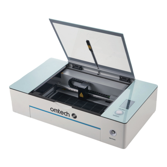
2.2 Designated Use The Polar+ is intended for engraving signs and logos on consumer products or applicable substrates. Its laser can process a wide variety of materials including wood and cork, paper and cardboard, most plastics, glass, cloth and leather, and stone. It can also be used with some specially coated metals. -
Page 18: Specifications
2 Introduction 2.3 Specifications Model Polar+ Input Power AC 110 V, 60 Hz Power Consumption 600 W Rated Power 55 W Expected Service Life 11,000 / 10,000 / 8,000 hr. at <40% / 40–70% / >70% Power 10.6 μm (10,600 nm) Laser Wavelength Diameter 2.2 in. - Page 19 Capacity 1.5 L Integrated Water Pump Flow Rate 540 L/hr. Port Diameter 0.3 in. 8 mm Integrated Air Assist Air Flow 13.8 cfm 392 L/min. Max. Resolution 5 MP Integrated Field of View 20.1×11.8 (in.) 510×300 (mm) Digital Camera ±0.04 in. ±1 mm Accuracy Rated Power...
-
Page 20: Package List
2 Introduction 2.4 Package List... - Page 21 Item Name Qty. 4-wheel Rotary Axes with Its Aviator Connection Cord Rotary Cables 60 W Duct Fan Fan Remote Control Adapter Ring Exhaust Pipes Diameter 150 mm, Length 2 m ×1; Diameter 120 mm, Length 3 m ×1 Hose Clamps Diameter 150 mm ×1;...
-
Page 22: Components
3 Components 3.1 Top View This small aviation plug connects to the provided rotary axes to Rotary Plug provide them with power and command signals. The 2.4 GHz wireless terminal device located behind the central part Wifi Card of the rear panel provides wifi connectivity for your engraver. This device transforms standard electricity into the extremely high Laser Power Supply voltage charge necessary for the laser tube. - Page 23 This tank helps keep your laser tube cool and stable. It arrives full of Water Tank OMTech antifreeze but can also be replaced with distilled water. This circuit board located under the left panel controls the engraving process, responding to commands from your computer’s engraving Mainboard software.
-
Page 24: Front View
3 Components 3.2 Front View This acrylic window allows you to monitor the engraving process, absorbing most reflected laser beams. However, always use Cover protective eyewear when observing the active laser and never stare at it for extended periods. Cover Interlocks These switches automatically pause work if the cover is opened. -
Page 25: Rear View
3.3 Rear View This dial provides a master power control for your engraver. It should Beam Attenuator be turned completely clockwise to enable your software to use the engraver’s full power range. This port functions as a second key necessary to activate the laser Remote Interlock tube. -
Page 26: Touch Screen
3 Components 3.4 Touch Screen 3.4.1 Home Interface Current File Name Current File Processing Duration Progress Display Work Status X, Y, Z Coordinates Button Function Definition Start/Pause Starts or pauses/restarts work. Stop Stops work. Pulse Fires the laser. Frame Checks out boundaries for the current pattern. Autofocus Autofocuses the leaser. - Page 27 Button Function Definition U Axis Moves the U Axis counterclockwise or clockwise. Coordinate Z Axis Moves the Z Axis up or down. Coordinate Y Axis Moves the Y Axis up or down. Coordinate X Axis Moves the X Axis left or right. Coordinate Position Sets a positioning point.
-
Page 28: Menu Interface
3 Components 3.4.2 Menu Interface Button Function Definition Sets the IP. When entering the interface, the current IP address of the board will be read. When touching the dialog box for the IP address, a small keyboard will pop up. Users can modify the host IP address using the keyboard. - Page 29 Button Function Definition Displays the hardware IO port information of the system. Diagnose U p o n e n t e r i n g t h e i n t e r f a c e , t h e s y s t e m h a r d w a r e information is read.
-
Page 30: Laser Head
3 Components 3.5 Laser Head This fixed mirror transfers the laser from the 2nd mirror at the end of 3rd Mirror the X-axis rail downward to the focus lens. This 15.5 mm lens directs and focuses the laser beam to its point of Focus Lens contact with your material. -
Page 31: Rotary Axes
3.6 Rotary Axes This plug should be covered during normal engraving. When you use Rotary Aviation Plug the rotary axes, the 4-pin connection will power and direct the rotary motor. These arrows indicate the correct position of the laser and the X-axis Alignment Arrows rail for use with Rotary Axis 1 (on the right) or Rotary Axis 2 (on the left). -
Page 32: Installation
4 Installation 4.1 Installation Overview A complete working system consists of the laser engraving machine, its integrated air assist and water pump, its vent and exhaust fan, its control computer, all applicable connection cables, the interlock connector, and the laser key. The engraver can receive designs and commands from the control computer directly from its USB cable or remotely from its wireless network or ethernet cable. - Page 33 • The power cord should be plugged into a compatible and stable power source via a grounded 3-prong outlet. No other item should be drawing current from the same circuit. There should be firefighting equipment nearby and the local fire department’s phone number should be clearly displayed.
-
Page 34: Unpacking
4 Installation 4.3 Unpacking Your engraver should have arrived in a wooden crate with its accessories (including this manual) packaged inside. You should place the crate in a spacious flat area for unpacking, ideally near where you plan to operate the machine permanently. Use at least two people to move and adjust the engraver’s position to help keep it level and avoid any sharp or sudden movement. -
Page 35: Checking The Cooling System
Open the cover and confirm that the plastic tank to the right of your main bay is full. The integrated water pump should arrive with about 1.5 L of OMTech coolant already in place. This should not require replacement during the first year of service, but refill it if the tank ever §... -
Page 36: Installing The Exhaust System
4 Installation 4.5 Installing the Exhaust System Wear work gloves to avoid cuts. The provided duct pipes extend to a total length of 16 ′ 4 ″ (5 m). Plan out the route that they will take from your engraver’s fan to a dedicated purifier or—if your engraving fumes and debris will not be hazardous and meet local and national air safety standards—to any window or exterior vent. - Page 37 8. Insert two batteries into the fan remote control. 9. Test if the fan works well. ALWAYS keep the fan remote control well, as the duct fan cannot work without it. • Turn it on by pressing Fast or Slow. •...
-
Page 38: Setting Up The Control System
4 Installation 4.6 Setting up the Control System Turn the beam attenuator fully clockwise. 2. Plug in the interlock connector. 3. Confirm the power switch is in the O position before setting up the control system. 4. Confirm that the voltage on the label above the laser’s power socket matches your local power supply. - Page 39 5. Connect the camera to your computer by using one USB cable.
- Page 40 4 Installation 6. Connect the engraver to your computer by using any of these 3 ways: a. Connect via the other USB cable. b. Connect via the ethernet cable. c. Connect via wi-fi. For instructions, see § 4.8 Wi-Fi Setup on Page 32.
- Page 41 8. Insert and turn the laser key clockwise.
-
Page 42: Setting Up Wi-Fi
Device on the lower right side of the main interface. If it is not visible, remove the other menus above it until it becomes visible. For LightBurn and other software setup, contact Customer Service, visit the OMTech website, or see our YouTube channel. - Page 43 4. Add a device. a. Select Setting and then Add. b. Toggle the selection to Web. c. Enter the IP address 192.168.1.100 if it is not automatically generated. d. Select OK. 5. Exit to the main interface, confirming and saving your changes. You can now use the dropdown menu in the Device area to switch between using the cable connection (USB: Auto) and the...
-
Page 44: Setting Up The Software
For LightBurn and other software setup, contact Customer Service, visit the OMTech website, or see our YouTube channel. 2. D o u b l e c l i c k t h e “ R D Wo r k s V 8 S e t u p 8.01.60-20211201.rar”, and then “RDWorksV8... - Page 45 b. Click Read. c. Click Open and then load the settings file “Manufacturer_parameters.RDVSet” from the USB. d. Click Write to save the parameters and then click Exit. 5. Configure the software parameters. a. P r e s s A LT + S ( “ C o n f i g ” ) a n d s e l e c t System Settings.
- Page 46 4 Installation b. Click Import Soft Para and load the file “Software_parameter.cfg”. 6. Configure the user parameters. a. On the System Work Platform on the upper right side of the main interface, change the tab from Work to User. b. Click Read. c.
- Page 47 7. Configure the camera. a. On Laser Work at the lower right side of the main interface, change the Position value from Current Position to Absolute Coordinates. b. On the Canvas Tools toolbar, click the u n l a b e l e d c h e c k b o x t o e n a b l e t h e canvas function and controls.
- Page 48 4 Installation d. Click Import Calibration and load the file Camera_calibration_file.calx.
- Page 49 8. Now the software is correctly configured for your engraver. Turn off your engraver if you are not going to use it. Familiarize yourself with your software’s image design and laser control features before using them to operate the laser.
-
Page 50: Initial Testing
5 Initial Testing Wear safety glasses during the entire test process! Always make sure the path is clear between the laser and its target. Never allow foreign objects between the laser and the material being engraved. Take care not to leave any part of your body in the laser path when it is in operation. -
Page 51: Interlock
5.1 Interlock Because of the risk of blindness, burns, and other injury from direct exposure to the invisible engraving beam, this device shuts off the laser automatically when parts of its protective housing are opened. Always make sure the path is clear between the laser and its target. Never allow foreign objects between the laser and the material being engraved. -
Page 52: Tray Shutoff
5 Initial Testing 8. Check the status of the engraver. The laser should pause automatically and the Start button should become red. If the laser continues to engrave the design while the cover is raised, the automatic shutoffs are not working and must be repaired before the engraver can be used. Turn off the machine and contact our technical support team. - Page 53 Engraving thick materials, using the front pass-through, or the rotary axes, however, requires this shutoff to be circumvented first. Mind that this the only safety feature that should ever be circumvented. To do so, Remove the debris tray and the workbed. 2.
-
Page 54: Interlock Connector Shutoff
5 Initial Testing 5.1.3 Interlock Connector Shutoff After ensuring that the cover and tray interlocks work properly, you should test that the remote interlock connector functions correctly. Perform the same procedure as before but, instead of opening the cover or tray, remove the interlock connector from its socket beside the power switch. -
Page 55: Laser Key Shutoff
5.2 Laser Key Shutoff After ensuring that the interlocks work properly, you should test that the laser key functions correctly. Perform the same procedure as before but, instead of opening the cover or tray, turn and remove the laser key. The laser should stop completely. -
Page 56: Water Shutoff
5 Initial Testing 5.3 Water Shutoff Because of the danger posed by an uncooled laser tube, this engraver also shuts off the laser automatically when its sensors do not detect the correct water flow. You should test that the water shutoff functions correctly: Perform the same procedure as before but, crimp or tie the water hoses instead, and attempt to fire the laser. -
Page 57: Air Assist
5.4 Air Assist Because of the danger posed by sparks during engraving and the risk of damage to the laser nozzle and focus lenses from fumes and debris, the pressurized air begins to blow from the laser head when the engraver starts engraving. You should test that the pressurized air blows correctly: Perform the same procedure as before. -
Page 58: Operation
6 Operation Operate this laser engraver only in accordance with all the instructions provided in this manual. Failure to follow these instructions can result in property damage and personal injury. Wear safety glasses during the entire test process! 6.1 Operation Overview This section will address only some of the options and features provided by the operation software. -
Page 59: General Operation
6.2 General Operation 6.2.1 Preparing Your Material Make sure that the engraver is powered off. 2. Open the cover. - Page 60 6 Operation 3. Confirm the thickness of your material with the provided ruler and place a sample piece into the main bay. The standard location is in the top right corner of the workbed. This can be changed by moving either your design or the origin position in your software.
- Page 61 Thickness Instructions Remove the tray and honeycomb workbed. 2. Cover the exposed area of your table with a non-reflective plank, preferably an MDF that fits the space. > 51 mm Warning! Failure to totally cover your table may cause a fire hazard. Using reflective surfaces risks reflecting the laser beam and destroying your engraver.
- Page 62 6 Operation Thickness Instructions 4. Slide the X-axis rail forward to expose the tray interlock switch. 5. Move the tray interlock switch into a closed position and hold it there by sliding the nearby metal bracket to the right. Tray Interlock Switch Bracket X-Axis Rail Never leave the switch in this position after completing your work.
- Page 63 b. Remove the debris tray and workbed. c. Slide the X-axis rail forward to expose the tray interlock switch. d. Move the tray interlock switch into a closed position and hold it there by sliding the nearby metal bracket to the right.
-
Page 64: Turning On Your Engraver
6 Operation 4. Confirm that the rotary switch is flipped down to its standard position and then close the cover. X-Axis Rail §6.3 Instructions for For round pieces, you will need to use a rotary axis. For instructions, see Rotary Operation on Page 65. -
Page 65: Loading Your Design
4. Turn on your engraver using its rear power switch and the laser key. 5. Confirm that the cooling system, air assist, exhaust fan, and internal lights have been activated. 6.2.3 Loading Your Design You can load your design in one of the following 3 ways. Select the option that best fits your needs. Via Your Control Computer Create the design that you’d like to engrave and save. - Page 66 6 Operation Via Your USB Disk Save your design into a .rd file under the root directory in the provided FAT32 USB disk. 2. Insert your USB disk onto the engraver. 3. Click File on the touch screen. 4. Set your design file as the current file by choosing it, clicking Copy to memory, and then clicking OK.
-
Page 67: Adjusting The Software's Parameters
6.2.4 Adjusting the Software’s Parameters Adjust your software’s parameters to suit your project. When working with new materials, remember that you should always start on the low end of likely settings. If the effect is not yet strong enough, you can always rerun the design loop several times or rerun it with more powerful settings until you create the effect that you want. -
Page 68: Engraving
6 Operation 6.2.5 Autofocusing Your Laser Autofocusing your laser every time you move the material or use a new material. Move the laser head over the sample material. 2. Press the autofocusing key on the touch screen. The laser head should automatically move toward the sample material, then move backward, and finally stop when the correct focal height has been reached. - Page 69 2. Begin engraving your design by clicking on the touch screen or the Start button in Laser Work on the lower right side of the software’s main interface. 3. Watch for possible issues like sparks or fires using the camera view. Do not stare continuously at the active laser even through your protective eyewear.
- Page 70 6 Operation 5. Once the laser has stopped, examine the quality of your first run. You can compare the engraving result of the material with that on the reference board. 6. Adjust the parameters in your software as necessary. You can adjust the values of power and speed based on the reference board.
-
Page 71: Shutdown
6.2.7 Shutdown When you have finished your project, close your engraving software. 2. Allow the cooling and ventilation systems to continue to run until the air in the main bay is clear and the tube has safely cooled. 3. Turn off the engraver using the laser key and the main power switch and then turn off the external fan. -
Page 72: Rotary Operation
6 Operation 6.3 Rotary Operation The Polar+ comes with two separate 4-wheel rotary axis devices to engrave spherical and cylindrical surfaces. Use Rotary Axis 1 for larger items and use Rotary Axis 2 for smaller ones. 6.3.1 Installing Your Rotary Axis Remove the debris tray and the honeycomb workbed. - Page 73 3. Slide the X-axis rail forward to expose the tray interlock switch. 4. Move the tray interlock switch into a closed position and hold it there by sliding the nearby metal bracket to the right. Never leave the switch in this position after completing your work.
- Page 74 6 Operation 6. Connect the rotary cable. a. Uncover the rotary aviation socket. b. Connect one of the rotary cables to the socket. You will need to pull back its outer sheath while aligning the 4 holes to their pins. c.
- Page 75 9. Enable the rotary axis function on your RDWorks V8 software by locating the Enable rotating function under User tab, and choose Yes. 10. Measure and fill in the Diameter parameter of the object on your RDworks V8 software. To measure Diameter, you can use either a ruler or a caliper, but a caliper provides an accurate reading.
-
Page 76: Preparing Your Material
6 Operation 6.3.2 Preparing Your Material ONLY engrave objects that the distance between its surface to the top of the laser mounting board can be 50.8 mm. 50.8 mm Object Place your object carefully onto the rotary axis. For a curved-surface object, use the adjusting knob to adjust the supporting bracket to an appropriate height. -
Page 77: Uninstalling Your Rotary Axis
6.3.3 Uninstalling Your Rotary Axis Gently move the laser tube and X-axis rail forward. X-Axis Rail 2. Flip the rotary switch up to Standard to activate the Y axis motors and control signals. 3. Disconnect the rotary cable from the rotary aviation socket and then cap the socket. - Page 78 6 Operation 5. Gently move the laser tube and X-axis rail back. 6. Take out your rotary axis. 7. Disconnect the rotary cable from the motor. 8. Replace the honeycomb workbed and the debris tray. 9. Close the cover.
- Page 79 10. Disable the rotary axis function on your RD Work s V8 softwar e by l ocati ng the Enable rotating function under User tab, and choose No.
-
Page 80: Instructions For Specific Materials
6 Operation 6.4 Instructions for Specific Materials The following instructions are suggestions to help speed safe work with a range of materials. The user should research the specific safety and engraving requirements of their specific material to avoid the risk of fire, hazardous dust, corrosive and poisonous fumes, and other potential problems. Once the product is known to be safe or appropriate protective equipment has been set up, it can be helpful to engrave a test matrix of small boxes produced at various speed and power settings to discover the ideal settings for your design. -
Page 81: Glass
6.4.2 Glass When engraving glass, generally use high power and low speed. As with ceramics, it can be helpful to run more loops at lower settings to avoid cracks. Care must be taken when engraving fiberglass and carbon fiber to avoid combinations of settings that produce a laser intensity great enough to damage the structural integrity of its component fibers, producing blurry markings. -
Page 82: Rubber
6 Operation 6.4.7 Rubber The various compositions and densities of rubber cause slightly varying engraving depths. Testing various settings on sample pieces of your specific rubber is highly recommended for the best results. When engraving rubber, generally use a consistent high-power setting and create your effects by varying the laser’s speed. -
Page 83: Maintenance
7 Maintenance 7.1 Maintenance Schedule The use of procedures other than those specified herein may result in hazardous laser radiation exposure. Before any cleaning or maintenance work, always switch off the engraver and disconnect it from its power supply. Always keep the system clean, as flammable debris in the working and exhaust areas constitutes a fire hazard. -
Page 84: Cleaning
7 Maintenance 7.2 Cleaning ALWAYS allow any fluid used in any cleaning to dry completely before further use of the engraver. 7.2.1 Cleaning the Main Bay and Engraver Check at least once a day whether dust has accumulated in the main engraving bay. If so, it must be removed. - Page 85 Interior of the Main Bay Do not use caustic chemicals or harsh abrasives. Be careful not to allow any electronic component to become wet and let all surfaces dry completely before further use. Do not leave standing water in the tray. •...
- Page 86 7 Maintenance • Removing the left panel requires unplugging its LED light. 3. Remove the screws and remove the panels.
- Page 87 4. Clean the right or left sides of the main bay thoroughly. 5. Replace them using the same screws and then restore the electrical connections. Exterior Do not use caustic chemicals or harsh abrasives. Be careful not to allow any electronic component to become wet and let all surfaces dry completely before further use.
-
Page 88: Cleaning The Camera, Mirrors, And Focus Lens
7 Maintenance 7.2.2 Cleaning the Camera, Mirrors, and Focus Lens Be careful in all of the following steps not to directly touch the surface of any of these windows, mirrors, or lenses with your finger or any dirty, oily, or abrasive surface. - Page 89 2. Clean the lens of the 3rd mirror and both sides of the focus lens in the same way as the 2nd mirror’s protective windows. 3. Gently remove any other dust or debris from other components inside the laser head and wipe the shell’s holes clean as well.
-
Page 90: Cleaning The Exhaust System
7 Maintenance Clean the camera Clean the camera lens in the same way. If any permanent spots or debris appear under the camera’s glass lens, it cannot be wiped clean and will require replacing the camera itself. Contact customer or technical support for details. -
Page 91: Cleaning The Cooling System
7.2.4 Cleaning the Cooling System NEVER touch or adjust your engraver’s water supply while your engraver is still connected to power. Your coolant tank should be shielded from ambient dust created during work. If your coolant ever becomes visibly dirty, discontinue work. The debris in the water will reduce its cooling efficiency, can heat up itself, and can damage the cooling pipes. -
Page 92: Refilling The Water Tank
7 Maintenance 7.3 Refilling the Water Tank NEVER touch or adjust your engraver’s water supply while your engraver is still connected to power. Always fill the chiller with deionized or distilled water or a custom-purpose laser- safe antifreeze. Using tap water for any purpose but rinsing out cleansers (see §... -
Page 93: Laser Path Alignment
7.4 Laser Path Alignment The Polar+ goes through a complete beam alignment before shipping and its design should keep your mirrors locked into their proper positions at all times. If you wish to test the alignment by using the laser to mark pieces of tape along its path to your material, remember to never place the tape directly on any mirrors or lenses, to never use power levels above 15% to mark the tape, and to never disable the cover’s interlock switches during your testing. -
Page 94: Parts Replacement
7 Maintenance 7.6 Parts Replacement ALWAYS completely disconnect the engraver from its power supply before replacing any parts. The engraver should not be modified or disassembled by anyone except trained and skilled professionals, but some consumable parts may require replacement after prolonged use. Be sure only to use identical or compatible replacement parts with this engraver. -
Page 95: Troubleshooting
8 Troubleshooting The common issues and solutions are listed below. For more detailed information on troubleshooting, please visit our official website omtechlaser.com. 8.1 Connection 8.1.1 The Engraver Can’t Find the Device Through Ethernet Cable Issue After powering the device on and connecting it to the computer with an Ethernet cable, the machine’s name can’t be found in the device list. -
Page 96: The Engraver Can't Find The Device Through Wi-Fi
8 Troubleshooting 8.1.2 The Engraver Can’t Find the Device Through Wi-Fi Issue After connecting the machine to the computer via Wi-Fi, the machine’s name can’t be found in the device list Solution Affected by VPN Close any VPN on your computer and restart the software to connect Software again. -
Page 97: The Engraver Can't Find Device Through Usb
8.1.3 The Engraver Can’t Find Device Through USB Issue After powering the device on and connecting it to the computer with a USB cable, the machine’s name can’t be found in the device list. Solution Check and make sure the connection is secure. Check the USB Cable Connection 2. -
Page 98: Hardware
8 Troubleshooting 8.2 Hardware 8.2.1 The Laser Tube Won’t Light Up Issue The laser tube won’t light up when trying to process after turning on the engraver. Do not touch the laser tube when it is illuminating. Solution As the laser tube ages, more power will be needed for the same level Adjust the Laser Power of laser activation as before. -
Page 99: The Engraver Won't Fire Laser
Solution Check the Power Have a technician check the power supply of the laser tube or contact Supply of the Laser our customer service support team for further analysis. Tube If none of the above works, the laser tube may be faulty. Please take a Replace the Laser Tube video of the problem, film the troubleshooting steps you have taken, and contact our service team for further assistance. -
Page 100: The Engraver Gets Non-Responsive After Power-On
8 Troubleshooting 8.2.3 The Engraver Gets Non-Responsive After Power-on Issue After the engraver is powered on by the rear switch, it doesn’t give any response. The ammeter display screen, light panel, water pump, motor, etc. won’t work at all. Solution Check the Power Cable Check if the power cable is properly plugged in on both ends. - Page 101 Scenario 1: If smoke evacuation remains poor If the smoke evacuation is still poor after removing the accessory devices, the issue may be related to the installation of the smoke exhaust fan. C h e c k t h e s m o k e Ensure that the smoke exhaust pipe is not pressed or bent, hindering exhaust pipe proper smoke evacuation.
-
Page 102: Not Cutting Through The Material
8 Troubleshooting 8.3.2 Not Cutting Through the Material Issue The engraver won’t fully and effectively cut through the material as expected. Solution For the materials suggested in this manual, you can choose the recommended parameter values for cutting. Check the Processing Parameters For those not suggested, you can get the ideal parameter values after several tests. - Page 103 Solution Use Compatible Some materials are not cuttable with the engraver. For recommended §1.6 Material Safety Instructions Material materials, see (Page 6). When the laser path is misaligned, the laser performance may vary significantly in different processing areas. Calibrate the Laser Path Contact our service to guide you on calibrating the laser path if the solutions above don’t work.
-
Page 104: Poor Engraving Results
8 Troubleshooting 8.3.3 Poor Engraving Results Issue When this issue occurs, you may find the engraving performance is not as expected: the pattern appears blurry, and the engraving outcome is excessively darkening or too shallow to be identified. Solution For materials suggested in this manual, you can choose the recommended parameter values for cutting. -
Page 105: Engraving Image Shifts During Processing
8.3.4 Engraving Image Shifts During Processing Issue The engraved image is deviated or won’t close up because of the losing steps in processing. Solution If the processing speed is too fast, it may cause step loss. Lower the Speed of the Engraving Process Please try again by lowering the speed. - Page 108 Scan for the latest user manual Polar+ | 55W | CO Desktop Laser Engraver User Manual U S B - 5 5 5 3 - U S R e v. 4 S e p t . 2 0 2 4...
Need help?
Do you have a question about the POLAR+ and is the answer not in the manual?
Questions and answers