Table of Contents
Advertisement
Quick Links
MS202E
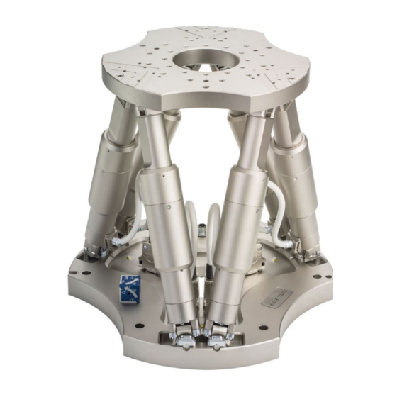
H-850 Hexapod Microrobot
User Manual
Version: 2.6.0
Physik Instrumente (PI) GmbH & Co. KG, Auf der Römerstraße 1, 76228 Karlsruhe, Germany
Phone +49 721 4846-0, fax +49 721 4846-1019, e-mail info@pi.ws, www.pi.ws
Date: 08/16/2024
This document describes the following hexapod
microrobots:
H-850.H2A
H-850.H2V
H-850.G2A
H-850.G2V
Advertisement
Chapters
Table of Contents

Related Manuals for PI H-850


Summary of Contents for PI H-850
- Page 1 This document describes the following hexapod microrobots: H-850.H2A H-850.H2V H-850.G2A H-850.G2V Physik Instrumente (PI) GmbH & Co. KG, Auf der Römerstraße 1, 76228 Karlsruhe, Germany Phone +49 721 4846-0, fax +49 721 4846-1019, e-mail info@pi.ws, www.pi.ws...
- Page 2 BiSS is a registered trademark of iC-Haus GmbH. © 2024 Physik Instrumente (PI) GmbH & Co. KG, Karlsruhe, Germany. The text, photographs, and drawings in this manual are protected by copyright. With regard thereto, Physik Instrumente (PI) GmbH & Co. KG retains all the rights.
-
Page 3: Table Of Contents
Unpacking Unpacking the Hexapod ................... 17 Removing the Transport Safeguard ................18 4.2.1 Removing the Transport Safeguard for the H-850.x2V Models ....18 4.2.2 Removing the Transport Safeguard for the H-850.x2A Models ....19 Installing General Notes on Installation ................... 21 Determining Valid Poses................... - Page 4 Packing the Hexapod for Transport ................36 7.3.1 Uninstalling the Hexapod ................36 7.3.2 Attaching the Transport Safeguard of the H-850.x2V Models ....37 7.3.3 Attaching the Transport Safeguard for the H-850.x2A Models ....38 7.3.4 Packing the Hexapod ................... 41...
-
Page 5: About This Document
About this Document Objective and Target Group of this User Manual This user manual contains the information necessary for using the H-850 as intended. We assume that the user has basic knowledge of closed-loop systems, motion control concepts, and applicable safety measures. -
Page 6: Figures
Photographic illustrations may also differ and must not be seen as guaranteed properties. Other Applicable Documents The devices and software tools from PI mentioned in this documentation are described in separate manuals. Device / program... - Page 7 5. For the desired manual, select ADD TO LIST and then REQUEST. 6. Fill out the request form and select SEND REQUEST. The download link will be sent to the email address entered in the form. H-850 Hexapod Microrobot MS202E Version: 2.6.0...
-
Page 9: Safety
Add all information from the manufacturer such as supplements or technical notes to the user manual. If you give the H-850 to other users, include this user manual as well as all other relevant information provided by the manufacturer. -
Page 10: Measures For Handling Vacuum-Compatible Products
When handling the vacuum model of the hexapod, attention must be paid to appropriate cleanliness. At PI, all parts are cleaned before assembly. During assembly and measurement, powder-free gloves are worn. Afterwards, the hexapod is cleaned once again by wiping and shrink-wrapped twice in vacuum-compatible film. -
Page 11: Product Description
Precision Hexapod microrobot, DC gear motor, rotary encoder, 25 kg load capacity, 2.5 mm/s velocity, vacuum compatible to 10 hPa, cable set 2 m vacuum side, feedthrough. Air side connecting cables are not included in the scope of delivery and must be ordered separately. H-850 Hexapod Microrobot MS202E Version: 2.6.0... -
Page 12: Product View
Each strut is equipped with the following components: Actuator Reference and limit switches Joints for connecting to the base plate and motion platform The actuator contains the following components: H-850.G2V, .H2V: DC motor with incremental rotary encoder Version: 2.6.0 MS202E H-850 Hexapod Microrobot... -
Page 13: Reference Switch And Limit Switches
3.3.3 Controller The hexapod is intended for operation with a suitable controller from PI (p. 15). With the controller, it is possible to command motion of individual axes, combinations of axes or all six axes at the same time in a single motion command. - Page 14 Translation Translations are described in the spatially-fixed coordinate system. The translational axes X, Y, and Z meet at the origin of the coordinate system (0,0,0). For further information, refer to the glossary (p. 69). Version: 2.6.0 MS202E H-850 Hexapod Microrobot...
- Page 15 1. The U axis is commanded to move to position 10. The rotation around the U axis tilts the rotational axes V and W. Platform in reference position Platform position: U = 10 (U parallel to spatially fixed Xaxis) H-850 Hexapod Microrobot MS202E Version: 2.6.0...
- Page 16 Platform position: U = 10, V = –10, W = 10 (U and V parallel to the platform level, W vertical to the platform level) For further data on the travel ranges, refer to the "Specifications" (p. 49) section. Version: 2.6.0 MS202E H-850 Hexapod Microrobot...
-
Page 17: Id Chip
H-850 Hexapod according to your order (p. 7) For the H-850.H2V and H-850.G2V vacuum-compatible models, a 2 m cable set for the vacuum side is included in the scope of delivery. Air side connecting cables are not included in the scope of delivery and must be ordered separately. -
Page 18: Optional Accessories
2 flat washers, form A-4.3 DIN 7090 2 lock washers, Schnorr Ø 4 mm N0110 Note that the cables required for connecting the H-850 to the electronics must be ordered separately. Optional Accessories Order number Data transmission cable, available lengths C-815.82D02... -
Page 19: Suitable Controllers
EtherCAT interface, motion stop C-887.533 6-axis controller for hexapods, TCP/IP, RS-232, benchtop device, incl. control of two additional axes, EtherCAT interface, motion stop, analog inputs To order, contact our customer service department (p. 47). H-850 Hexapod Microrobot MS202E Version: 2.6.0... -
Page 21: Unpacking
When handling the vacuum model of the hexapod, attention must be paid to appropriate cleanliness. At PI, all parts are cleaned before assembly. Powder-free gloves are worn during assembly and measuring. In addition, the hexapod is wipe cleaned afterwards and then shrink- wrapped twice in vacuum-compatible film. -
Page 22: Removing The Transport Safeguard
4 Unpacking Removing the Transport Safeguard 4.2.1 Removing the Transport Safeguard for the H-850.x2V Models Figure 3: Transport safeguard components Hexapod with transport safeguard attached Transport safeguard with fixing screws Tools and accessories Hex key 5.0 from the supplied screw set (p. 13). -
Page 23: Removing The Transport Safeguard For The H-850.X2A Models
4 Unpacking 4.2.2 Removing the Transport Safeguard for the H-850.x2A Models Figure 4: Transport safeguard components Cover M6x16 screw M8 nut Strut Tools and accessories Open-end wrench AF 10 Open-end wrench AF 13 Removing the transport safeguard 1. Loosen the 4 nuts (M8) used for securing the transport safeguard's cover to the struts. -
Page 25: Installing
Make sure that no collisions between the hexapod, the load to be moved, and the surroundings are possible in the workspace of the hexapod. H-850 Hexapod Microrobot MS202E Version: 2.6.0... -
Page 26: Determining Valid Poses
Load to be moved: mass and position of the center of mass on the motion platform Forces and torques acting on the motion platform Poses to be approached by the motion platform during operation (coordinates for translation and rotation) Version: 2.6.0 MS202E H-850 Hexapod Microrobot... -
Page 27: Grounding The Hexapod
Mount the hexapod onto a flat surface. The recommended flatness of the surface is 300 µm. Requirements You have read and understood the General Notes on Installation (p. 21). Tools and accessories Hex key 5.0 and six of the M6x30 screws (p. 13) supplied. H-850 Hexapod Microrobot MS202E Version: 2.6.0... -
Page 28: Fixing The Load To The Hexapod
(p. 57) together with the load to be mounted. Only use screws that do not project under the motion platform after being screwed in. Only mount the hexapod and the load on the mounting fixtures (holes) intended for this purpose. Version: 2.6.0 MS202E H-850 Hexapod Microrobot... - Page 29 The layout of the mounting and locating holes in the motion platform of the hexapod as well as the tolerance values can be found in the dimensional drawing (p. 57). 2. Use the screws to fix the load to the selected mounting holes in the motion platform. H-850 Hexapod Microrobot MS202E Version: 2.6.0...
-
Page 30: Optional: Removing The Coordinate Cube
Tools and accessories Data transmission cable and power supply cable, available as accessories (p. 14) If you want to operate a vacuum-compatible hexapod in a vacuum chamber: Suitable tools for installing the vacuum feedthrough Version: 2.6.0 MS202E H-850 Hexapod Microrobot... - Page 31 5 Installing If necessary: Installing vacuum feedthroughs Figure 6: Vacuum feedthrough for data transmission (4668), dimensions in mm 4 holes, Ø6 x 45° for M3 countersunk screw H-850 Hexapod Microrobot MS202E Version: 2.6.0...
- Page 32 Pay attention to the assignment specified on the labeling of the sockets, plug − connectors, and cables. − Pay attention to the mechanical coding of connectors and sockets. − Do not use force. Use the integrated screws to secure the connections against accidental − disconnection. Version: 2.6.0 MS202E H-850 Hexapod Microrobot...
- Page 33 Socket / connector, female Controller Refer to "Suitable Controllers (p. 15)" Hexapod H-850.H2A, .G2A Power adapter, from the scope of delivery of the controller, 24 V DC output Data transmission cable Power supply cable H-850 Hexapod Microrobot MS202E Version: 2.6.0...
- Page 34 Vacuum feedthrough for data transmission** Data transmission cable vacuum side** Vacuum feedthrough for power supply** Power supply cable, vacuum side** * Must be ordered separately ** From the scope of delivery of the hexapod (p. 13) Version: 2.6.0 MS202E H-850 Hexapod Microrobot...
-
Page 35: Startup
Do not place any objects in areas where they can be caught by moving parts. Only command valid poses. See "Determining Valid Poses" (p. 22) for the definition of a valid pose. Stop the motion immediately if a controller malfunction occurs. H-850 Hexapod Microrobot MS202E Version: 2.6.0... -
Page 36: Starting Up The Hexapod System
The longer the bakeout and cooling process takes, the more the maintenance runs are necessary. Perform a maintenance run during the bakeout and cooling process at least once a day. Version: 2.6.0 MS202E H-850 Hexapod Microrobot... - Page 37 Bake out the hexapod at maximum 80 °C (176 °F). Perform a maintenance run (p. 35) over the entire travel range during the bakeout and cooling process at least once a day. H-850 Hexapod Microrobot MS202E Version: 2.6.0...
-
Page 39: Maintenance
7 Maintenance Maintenance PI offers a range of wraparound services for all their products, many of which are designed to increase the system’s lifetime and uptime: Remote system setup: An expert ensures that your system is optimized and runs ... -
Page 40: Packing The Hexapod For Transport
Loosen all connections between the cables attached permanently to the hexapod and the cable set used, and remove the cables from all attachments (e.g., connector holder). e) Remove the hexapod from the surface. Version: 2.6.0 MS202E H-850 Hexapod Microrobot... -
Page 41: Attaching The Transport Safeguard Of The H-850.X2V Models
7 Maintenance 7.3.2 Attaching the Transport Safeguard of the H-850.x2V Models Tools Open-end wrench SW 10 Open-end wrench SW 13 Suitable screwdriver Figure 10: Transport safeguard on the motion platform 1 - Transport safeguard 2 - Motion platform... -
Page 42: Attaching The Transport Safeguard For The H-850.X2A Models
7 Maintenance 4. Fasten the transport safeguard with 4 screws (M6x20) on the side of the base plate (see figure). 7.3.3 Attaching the Transport Safeguard for the H-850.x2A Models Tools Open-end wrench SW 10 Open-end wrench SW 13 ... - Page 43 Tighten the struts hand-tight. 2. Attach the nuts and flat washers: a) On each strut, screw an M8 nut down to the thread end. b) Put an 8.4 flat washer onto each nut. H-850 Hexapod Microrobot MS202E Version: 2.6.0...
- Page 44 Attach the cover to the motion platform using the four M6x16 screws that you previously pushed a 6.4 flat washer onto. 4. Attach the cover to the struts: a) Push an 8.4 flat washer onto each strut. b) Place an M8 nut on each strut and hand-tighten. Version: 2.6.0 MS202E H-850 Hexapod Microrobot...
-
Page 45: Packing The Hexapod
Lock each nut above with the nut below the cover for each strut. b) Put thread protection caps onto the strut ends. The installation is then finished. 7.3.4 Packing the Hexapod Proceed as described in H850T0001 (in the scope of delivery (p. 13)). H-850 Hexapod Microrobot MS202E Version: 2.6.0... -
Page 47: Troubleshooting
Faulty motor occurs with maximum or minimum Sensor defective displacement of the platform in Z. Blocked or broken Contact our customer service department joint (p. 47). H-850 Hexapod Microrobot MS202E Version: 2.6.0... - Page 48 "Using the E-Stop Socket" in the user motion from being manual of the C-887.5xx controller. triggered Check the Power Good signal and the activation state of the 24 V output for the hexapod (24 V Out 7 A). Options: Version: 2.6.0 MS202E H-850 Hexapod Microrobot...
- Page 49 ID chip. Example for the response: IDChip: H-811.F-2 SN123456789 20/1/2016send the CST? command. The response shows the hexapod, to which the H-850 Hexapod Microrobot MS202E Version: 2.6.0...
- Page 50 If the problem with your hexapod is not listed in the table or cannot be solved as described, contact our customer service department (p. 47). Version: 2.6.0 MS202E H-850 Hexapod Microrobot...
-
Page 51: Customer Service Department
9 Customer Service Department Customer Service Department For inquiries and orders, contact your PI representative or send us an email (mailto:service@pi.de). If you have questions concerning your system, provide the following information: − Product and serial numbers of all products in the system Firmware version of the controller (if applicable) −... -
Page 53: Technical Data
3 mrad/s Typical angular velocity in θZ 75 mrad/s 3 mrad/s Positioning H-850.G2A H-850.H2A Tolerance Minimum incremental motion in X 1 µm 0.3 µm typ. Minimum incremental motion in Y 1 µm 0.3 µm typ. H-850 Hexapod Microrobot MS202E Version: 2.6.0... - Page 54 Maximum load capacity, base plate 50 kg 250 kg horizontal Maximum holding force, base plate in any 85 N 500 N orientation Maximum holding force, base plate 250 N 1282 N horizontal Overall mass 17 kg 17 kg Version: 2.6.0 MS202E H-850 Hexapod Microrobot...
- Page 55 1.2 mrad/s Typical angular velocity in θY 25 mrad/s 1.2 mrad/s Typical angular velocity in θZ 25 mrad/s 1.2 mrad/s Positioning H-850.G2V H-850.H2V Tolerance Minimum incremental motion in X 1 µm 0.3 µm typ. H-850 Hexapod Microrobot MS202E Version: 2.6.0...
- Page 56 40 kg orientation Maximum load capacity, base plate 25 kg 80 kg horizontal Maximum holding force, base plate in any 85 N 500 N orientation Maximum holding force, base plate 250 N 1282 N horizontal Version: 2.6.0 MS202E H-850 Hexapod Microrobot...
-
Page 57: Specifications For Data Transmission And Power Supply Cables
0,0,0. At PI, technical data is specified at 22 ±3 °C. Unless otherwise stated, the values are for unloaded conditions. Some properties are interdependent. The designation "typ." indicates a statistical average for a property; it does not indicate a guaranteed value for every product supplied. During the final inspection of a product, only selected properties are analyzed, not all. -
Page 58: Minimum Bending Radius In A Drag Chain
Maximum number of bending cycles 1 million Operating temperature range -10 to +70 °C Power supply cable, straight connectors Unit Minimum bending radius in a drag chain Minimum bending radius with the fixed 24.5 installation Version: 2.6.0 MS202E H-850 Hexapod Microrobot... -
Page 59: Connector M12 M/F
Power supply cable, angled connector K040B0254 K060B0132 General Unit Cable length L Operating temperature range -10 to +80 °C Data transmission cable Unit Minimum bending radius with the fixed installation Outer diameter Connectors HD D-sub78 m/f H-850 Hexapod Microrobot MS202E Version: 2.6.0... -
Page 60: Maximum Ratings
Highest relative humidity of 80% at temperatures of up Humidity: to 31°C, decreasing linearly to a relative humidity of 50% at 40°C Degree of protection according IP20 to IEC 60529 Area of application For indoor use only Maximum altitude 2000 m Version: 2.6.0 MS202E H-850 Hexapod Microrobot... -
Page 61: Dimensions
X=Y=Z=U=V=W=0, the center of rotation is at the origin of the coordinate system. Dimensions in mm. Note that a comma is used in the drawings instead of a decimal point. Figure 11: H-850.x2V, at zero position of nominal travel range H-850 Hexapod Microrobot MS202E Version: 2.6.0... - Page 62 10 Technical Data Gleichung 1: H-850.x2A, at zero position of nominal travel range Version: 2.6.0 MS202E H-850 Hexapod Microrobot...
-
Page 63: Load Curves
The load curves in the following figures only apply when the hexapod is connected to the controller and the servo mode is switched on. Figure 12: Maximum loads of the H-850.G2A when mounted horizontally Figure 13: Maximum loads of the H-850.G2A when mounted vertically... - Page 64 10 Technical Data Figure 14: Maximum loads of the H-850.G2A when mounted at the most unfavorable angle Figure 15: Maximum permissible force acting on the H-850.G2A when mounted horizontally Version: 2.6.0 MS202E H-850 Hexapod Microrobot...
- Page 65 10 Technical Data Figure 16: Maximum loads of the H-850.H2A when mounted horizontally Figure 17: Maximum loads of the H-850.H2A when mounted vertically H-850 Hexapod Microrobot MS202E Version: 2.6.0...
- Page 66 10 Technical Data Figure 18: Maximum loads of the H-850.H2A when mounted at the most unfavorable angle Figure 19: Maximum permissible force acting on the H-850.H2A when mounted horizontally Version: 2.6.0 MS202E H-850 Hexapod Microrobot...
- Page 67 10 Technical Data Figure 20: Maximum loads of the H-850.H2V when mounted horizontally Figure 21: Maximum loads of the H-850.H2V when mounted vertically H-850 Hexapod Microrobot MS202E Version: 2.6.0...
-
Page 68: Pin Assignment
10 Technical Data Figure 22: Maximum loads of the H-850.H2V when mounted at the most unfavorable angle 10.6 Pin Assignment 10.6.1 Power Supply Connector Not for vacuum models: Power supply via 4-pin M12 panel plug Function 24 V DC 24 V DC Version: 2.6.0... -
Page 69: Data Transmission Connector
CH1 B+ OUT CH1 A- OUT CH1 B- OUT CH2 Sign IN CH2 MAGN IN CH2 Ref OUT CH2 LimP OUT CH2 LimN OUT CH2 A+ OUT CH2 B+ OUT CH2 A- OUT CH2 B- OUT H-850 Hexapod Microrobot MS202E Version: 2.6.0... - Page 70 CH6 MAGN IN CH6 Ref OUT CH6 LimP OUT CH6 LimN OUT CH6 A+ OUT CH6 B+ OUT CH6 A- OUT CH6 B- OUT ID Chip Brake/Enable drive 24 V input Power Good 24 V output Version: 2.6.0 MS202E H-850 Hexapod Microrobot...
-
Page 71: Old Equipment Disposal
PI equipment made available on the market after 13 August 2005 without charge. If you have an old device from PI, you can send it to the following address free of charge: Physik Instrumente (PI) GmbH & Co. KG... -
Page 73: Glossary
The center of rotation that can be moved using the SPI command is also referred to as "pivot point". Hexapod system The combination of hexapod, controller, cables, and power adapter(s) is referred to as "hexapod system" in this manual. H-850 Hexapod Microrobot MS202E Version: 2.6.0... - Page 74 The Z axis is perpendicular to the base plate of the hexapod. The following example figures of the H-810 hexapod show that the coordinate system does not move along with motion of the platform. Figure 23: H-810 hexapod in the reference position. Cable exit Version: 2.6.0 MS202E H-850 Hexapod Microrobot...
- Page 75 12 Glossary Figure 24: H-810 hexapod, the platform of which has been moved in X. Cable exit H-850 Hexapod Microrobot MS202E Version: 2.6.0...
-
Page 77: Appendix
The following test cycles are performed: Motion over the entire travel range with at least 20 measuring points, in at least five cycles. Motion over partial sections, e.g., ±1 mm in increments of for example, 100 µm H-850 Hexapod Microrobot MS202E Version: 2.6.0... -
Page 79: European Declarations Of Conformity
13 Appendix 13.2 European Declarations of Conformity For the H-850, declarations of conformity were issued according to the following European statutory requirements: EMC Directive RoHS Directive The standards applied for certifying conformity are listed below. EMC: EN 61326-1 Safety: EN 61010-1...
Need help?
Do you have a question about the H-850 and is the answer not in the manual?
Questions and answers