Table of Contents
Advertisement
Quick Links
MP113E
M-5x1 High-Precision Linear Stage
User Manual
Version: 2.0.0
PI miCos GmbH, Freiburger Strasse 30, 79427 Eschbach, Germany
Phone +49 7634 5057-0, Fax +49 7634 5057-99, Email info@pimicos.com, www.physikinstrumente.com/en/
Date: 2022-10-20
This document describes the following linear stages:
M-5x1.DDx:
with ActiveDrive DC motor, linear encoder
M-5x1.DG1:
with DC gear motor, rotary encoder
M-5x1.EC:
with brushless DC motor, rotary encoder
M-5x1.PD1:
with ActiveDrive DC motor, PWM, rotary encoder
M-5x1.PG1:
with DC gear motor, PWM, rotary encoder
x stands for travel range:
1 = 102 mm
2 = 204 mm
3 = 306 mm
Advertisement
Table of Contents

Related Manuals for PI MP113E


Summary of Contents for PI MP113E
- Page 1 DC gear motor, PWM, rotary encoder x stands for travel range: 1 = 102 mm 2 = 204 mm 3 = 306 mm PI miCos GmbH, Freiburger Strasse 30, 79427 Eschbach, Germany Phone +49 7634 5057-0, Fax +49 7634 5057-99, Email info@pimicos.com, www.physikinstrumente.com/en/...
- Page 2 NEXACT®, Picoactuator®, PInano®, NEXSHIFT®, PITOUCH®, PIMag®, PIHera, Q-Motion® © 2022 Physik Instrumente (PI) GmbH & Co. KG, Karlsruhe, Germany. The text, photographs, and drawings in this manual are protected by copyright. With regard thereto, Physik Instrumente (PI) GmbH & Co. KG reserves all rights.
-
Page 3: Table Of Contents
Contents About this Document Objective and Target Group of this User Manual ............1 Symbols and Typographic Conventions..............1 Definition of Terms ..................... 2 Figures ........................2 Other Applicable Documents ..................2 Downloading Manuals ....................3 Safety Intended Use ......................5 General Safety Instructions .................. - Page 4 Startup and Operation General Notes on Startup ..................37 Startup and Operation of the Positioner ..............39 6.2.1 M-5x1 Entries in the PI Positioner Database ..........39 Maintenance General Notes on Maintenance ................41 Performing Maintenance ..................41 Cleaning the M-5x1 ....................41 Troubleshooting General Notes on Troubleshooting ................
-
Page 5: About This Document
1 About this Document About this Document Objective and Target Group of this User Manual This user manual contains the information needed for using the M-511, M-521, and M-531 (hereafter also referred to as called M-5x1) as intended. Basic knowledge of closed-loop systems, motion control concepts, and applicable safety measures is assumed. -
Page 6: Definition Of Terms
Photographic illustrations may also differ and must not be seen as guaranteed properties. Other Applicable Documents The devices and software tools from PI mentioned in this documentation are described in separate manuals. Version: 2.0.0 M-5x1 High-Precision Linear Stage... -
Page 7: Downloading Manuals
1 About this Document Product Document C-863.12 DC Motor Controller MS249 User Manual C-663.12 Stepper Motor Controller MS241 User Manual C-884 DC Motor Controller MS243 User Manual C-885 PIMotionMaster C885T0002 User Manual C-863.12C885 for C-885 PIMotionMaster C863T0004 User Manual C-863.20C885 for C-885 PIMotionMaster C863T0005 User Manual The latest versions of the user manuals are available for download on our website. -
Page 9: Safety
2 Safety Safety Intended Use The M-5x1 is a laboratory device as defined by DIN EN 61010. It is intended for indoor use in an environment which is free of dirt, oil, and lubricants. According to its design, the M-5x1 is intended for positioning, adjusting, and shifting loads in one axis at different velocities. -
Page 10: Organizational Measures
2 Safety Organizational Measures User manual Always keep this user manual together with the M-5x1. The latest versions of the user manuals are available for download on our website (p. 2). Add all information from the manufacturer such as supplements or technical notes to the user manual. -
Page 11: Product Description
3 Product Description Product Description Model Overview Classification of the positioners The stages of the M-511, M-521 and M-531 series are summarized under the designation M-5x1 in this manual. All models are microtranslation stages with a ball screw. They differ with respect to: ... - Page 12 3 Product Description Detailed model overview Product number Product Description M-511.DD1 Microtranslation stage, 102 mm, ActiveDrive DC motor, linear encoder M-511.DD2 Microtranslation stage, 102 mm, ActiveDrive DC motor, linear encoder, motor brake M-511.DG1 Microtranslation stage, 102 mm, DC gear motor, rotary encoder M-511.EC Microtranslation stage, 102 mm, brushless DC motor, rotary encoder M-511.PD1...
-
Page 13: Product View
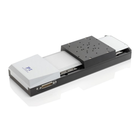
3 Product Description Product View Figure 1: Positioner components (here: M-511) Base body Motor cover Spindle cover Motion platform Power adapter connector (M8 panel plug; not .DG1 models) Controller connector (D-sub 15 panel plug) M-5x1 High-Precision Linear Stage Version: 2.0.0... -
Page 14: Product Labeling
Figure 2: Product labeling Position Labeling Description "Risk of crushing" warning sign Manufacturer's logo WWW.PI.WS Manufacturer's address (website) M-511.DD1 Product name (example), the characters following the period refer to the model SN: A16045786 Serial number (example), individual for each M-... -
Page 15: Scope Of Delivery
3 Product Description Scope of Delivery Product number Description M-5x1.xxx Positioner according to the order (p. 7) 2504 Screw set for attaching the stage, load and mounting adapters 4 socket head screws, A2 M4×16 ISO 4762 4 socket head screws, A2 M4x30 ISO 4762 4 socket head screws, A2 M6×30 ISO 4762 ... -
Page 16: Suitable Controllers
Motion controller module for DC motors, for C-885 PIMotionMaster C-884 Controller for DC motors PC software is included in the scope of delivery of the controllers from PI. The operation of the controllers is described in the corresponding user manuals. Technical Features 3.7.1... - Page 17 The gap between N1 and N2 or P1 and P2 is approx. 5.3 mm in each case. INFORMATION In the case of controllers from PI, the permissible travel range of the positioner is represented via parameters in the controller. Suitable parameter values can be loaded from a positioner database in the supplied PC software;...
-
Page 18: Reference Switch
The M-5x1.DD2 models are equipped with a motor brake. Positioners with a motor brake are especially suited for vertical mounting. The motor brake is activated and deactivated via the connected controller. Controllers from PI activate the brake automatically when servo mode is switched off. Refer to the user manual for the controller for details. -
Page 19: Unpacking
4 Unpacking Unpacking 1. Unpack the M-5x1 with care. 2. Compare the contents with the scope of delivery according to the contract and the delivery note. 3. Inspect the contents for signs of damage. If any parts are damaged or missing, contact our customer service department immediately. -
Page 21: Installing
5 Installing Installing General Notes on Installing NOTICE Unwanted changes in position when mounted vertically! If the load exceeds the self-locking of the drive when the stage is mounted vertically, unwanted changes in the position of the platform occur. Unwanted changes in the position of the platform can damage the drive, the load, or the surroundings. -
Page 22: Attaching The M-5X1 To An Underlying Surface
INFORMATION The holes in the motion platform of the M-5x1 are arranged in the PI standard hole pattern. The PI standard hole pattern is used with many micropositioning stages from PI and allows a simple combination of linear and rotation stages with minimum effort. - Page 23 5 Installing INFORMATION The M-5x1 can be fixed to an underlying surface with M6 or M4 screws. Advantages when the positioner is installed with M6 screws: The holes for M6 screws are freely accessible in the delivery state. M6 screws can absorb greater forces than M4 screws. ...
-
Page 24: Using Adapters For The 25 Mm × 25 Mm Hole Pattern
An adapter is necessary to attach the M-5x1 to a commercially available honeycomb plate with a hole pattern of 25 mm × 25 mm and M6 screws. PI offers the M-590.00 two-part three-point support as an adapter, see "Accessories" (p. 11). - Page 25 5 Installing Figure 5: M-5x1 with adapter (M-590.00 three-point support) on a honeycomb plate Figure 6: Individual components to be connected with relevant holes Stage (here M-511) Wide adapter plate, part of the M-590.00 three-point support Narrow adapter plate, part of the M-590.00 three-point support Honeycomb plate with 25 mm ×...
- Page 26 5 Installing Tools and accessories M-590.00 three-point support, two-part, available as an optional accessory (p.11). For attachment of the M-590.00 three-point support to the M-5x1: − 4 M6x30 screws, included in the scope of delivery Hex key, AF 5, included in the scope of delivery −...
-
Page 27: Fixing The Load To The M-5X1
5 Installing Fixing the Load to the M-5x1 NOTICE Impermissibly high load on the positioner! An impermissible high load impairs the motion of the platform and can damage the positioner. When considering the mass and mounting method of the load, pay attention to the specified maximum permissible forces that may act on the platform (p. -
Page 28: Building A Multi-Axis System
5 Installing Fixing the load Figure 7: Holes in the motion platform of the M-5x1 M4 mounting hole, depth 8 mm (total of 27) Central M6 mounting hole, depth 8 mm Locating hole Ø 4 mm H7, depth 5 mm (total of 4) 1. -
Page 29: General Notes On Building A Multi-Axis System
5 Installing Figure 8: Example of an XYZ system: two M-511.DD1 positioners / one M-501.1PD Z stage M-501.PD Z stage, directly mounted Upper stage (here: M-511.DD1), directly mounted Lower stage (here: M-511.DD1) 5.4.1 General Notes on Building a Multi-Axis System NOTICE Impermissibly high load on the positioners! In a multi-axis system, the positioner must also be moved for the Y and/or Z axis. -
Page 30: Building An Xy System
5 Installing NOTICE Wear from moving the platform by hand! Moving the platform by hand increases wear in the case of positioners with a gearhead. In the case of the M-5x1.DG1 und .PG1 models, move the platforms by hand only if they cannot be moved in any other way. - Page 31 5 Installing Figure 10: Example: Building an XY system with two M-511 positioners Lower positioner with a – d) M4 mounting holes in the platform Upper positioner (motion platform at the positive end of the travel range) with a – d) mounting holes with counterbore for M4 socket head screws in the base body of the positioner Holes that are aligned during attachment are marked with the same letter.
-
Page 32: Building A Z System With An Adapter Bracket
5 Installing Tools and accessories 4 M4 screws of a suitable length from the scope of delivery of the upper positioner If an M-5x1 is mounted to another M-5x1 as in the figure above: 2 M4x30 screws − Hex key AF 3, included in the positioner's scope of delivery ... - Page 33 5 Installing Figure 11: Example: XZ combination consisting of two M-511 positioners Lower positioner M-592.10 adapter bracket Upper positioner M4 screw Requirements You have read and understood the general notes on installation (p. 17). You have read and understood the general notes on building a multi-axis system (p.
- Page 34 5 Installing Tools and accessories Suitable adapter bracket, available as an optional accessory (p. 11): M-592.10 if using an M-5x1 positioner as the Z axis − For attaching the Z axis to the adapter bracket: 4 M4 screws of a suitable length ...
- Page 35 5 Installing Building a Z system Figure 12: Example: Building an XZ combination with two M-511 positioners M-592.10 adapter bracket Upper positioner (view of bottom) Lower positioner a – g: Mounting holes: Holes that are aligned during attachment are marked with the same letter 1.
- Page 36 5 Installing Figure 13: Attaching the upper positioner to the adapter bracket a) Position the upper positioner on the long surface of the adapter bracket as in the figure: − The positioner lies on the inside of the bracket. − The motor cover of the positioner faces the open end of the inside of the bracket (i.e., upwards in the Z system).
- Page 37 5 Installing Figure 14: Attaching the adapter bracket to the lower positioner a) Position the adapter bracket to which the upper stage is fixed on the motion platform of the lower stage as in the figure. − The open end of the short side of the bracket faces the motor cover of the lower positioner.
-
Page 38: Connecting The M-5X1 To A Controller
5 Installing Connecting the M-5x1 to a Controller Requirements You have read and understood the general notes on installation (p. 17). You have installed the controller. You have read and understood the user manual for the controller. ... - Page 39 5 Installing Connecting the power adapter to the M-571 Connect the M8 connector (f) of the adapter to the M8 panel plug of the M-5x1. Connect the barrel connector on the adapter to the barrel connector socket of the power adapter.
-
Page 41: Startup And Operation
6 Startup and Operation Startup and Operation General Notes on Startup CAUTION Risk of crushing by moving parts! Risk of minor injury from crushing between the moving parts of the positioner or the load and a fixed part or obstacle. ... - Page 42 6 Startup and Operation NOTICE Operating voltage excessively high or incorrectly connected! Excessively high or incorrectly connected operating voltages could cause damage to the M-5x1. Do not exceed the operating voltage range (p. 51) specified for the M-5x1. Operate the M-5x1 only when the operating voltage is properly connected; see "Pin assignment"...
-
Page 43: Startup And Operation Of The Positioner
Configure the controller during startup using the PC software for the positioner (refer to the user manual for the controller, and the PC software): If you are using a controller from PI: Select the entry in the positioner database that −... -
Page 45: Maintenance
7 Maintenance Maintenance General Notes on Maintenance NOTICE Damage due to improper maintenance! Removing caps and screws could lead to contamination and failure of the M-5x1. Do not loosen any screws on the positioner. Do not remove any other caps except the protective caps. Performing Maintenance Depending on the operating conditions and the period of use of the M-5x1, the following maintenance measures are required:... -
Page 47: Troubleshooting
Perform a maintenance run over the entire motion over a long period of time travel range (p. 41). Function impairment Controller was replaced. Controller from PI: after system M-5x1 was replaced by Load the parameters from the positioner modification another model. - Page 48 If applicable: Check the positioner's power adapter. When a PI controller is used: Axis Motion error = the difference between the motion error. current position and the commanded position exceeds the specified maximum value in closed-loop operation.
-
Page 49: Moving The Platform By Hand
8 Troubleshooting Moving the Platform by Hand NOTICE Wear from moving the platform by hand! Moving the platform by hand increases wear in the case of positioners with a gearhead. In the case of the M-5x1.DG1 und .PG1 models, move the platforms by hand only if they cannot be moved in any other way. - Page 50 8 Troubleshooting Tools Hex key, AF 3 (included in the scope of delivery) Moving the platform manually 1. Remove the drive-screw access cap on the front face of the positioner (for the position see figure). 2. Insert the hex key into the drive-screw access until you feel resistance. 3.
-
Page 51: Customer Service
9 Customer Service Customer Service For inquiries and orders, contact your PI sales engineer or send us an email (service@pi.de). If you have questions concerning your system, provide the following information: Product and serial numbers of all products in the system −... -
Page 53: Technical Data
10 Technical Data Technical Data 10.1 Specifications 10.1.1 Data Table Motion M-5x1.DD1 / .DD2 M-5x1.DG1 / .PG1 M-5x1.EC / .PD1 Unit Tolerance Active axis Travel range M-511: 102 (4‘‘) / M-521: 204 (8‘‘) / M-531: 306 (12‘‘) Pitch (rotational ±25 or 35 ±35 ±35 µrad... - Page 54 10 Technical Data Positioning: M-5x1.DD1 / .DD2 M-5x1.DG1 / .PG1 M-5x1.EC / .PD1 Unit Tolerance Unidirectional µm Typ. repeatability Bidirectional ±0.2 ±1 ±1 µm Typ. repeatability Limit switches Hall effect Hall effect Hall effect Reference switch Hall effect Hall effect Hall effect Mechanical properties M-5x1.DD1 / .DD2 M-5x1.DG1 / .PG1...
-
Page 55: Maximum Ratings
10 Technical Data Drive properties M-5x1.DD1 / .DD2 M-5x1.DG1 / .PG1 M-5x1.EC / .PD1 Unit Tolerance Drive force in negative Typ. direction of motion in X Drive force in positive Typ. direction of motion in X Note on pitch, yaw, straightness, flatness: Specified value applies per 100 mm Note on gear ratio: (28/12)4 ~ 29.6 : 1 10.1.2 Maximum Ratings... -
Page 56: Limit Switch Specifications
10 Technical Data 10.1.4 Limit Switch Specifications Type Magnetic (Hall effect) sensor Supply voltage +5 V/GND, supplied via the motor connector Signal output TTL level Signal logic Active high. The signal level changes when passing the limit switch: Normal motor operation: low (0 V) ... -
Page 57: Dimensions
10 Technical Data 10.2 Dimensions Dimensions in mm. Note that a comma is used in the drawings instead of a decimal point. 10.2.1 Positioner M-5x1 Figure 16: Dimensions of the M-5x1 M-5x1 High-Precision Linear Stage Version: 2.0.0... -
Page 58: Hole Pattern Of The Motion Platform
27 undimensioned holes: M4 thread, 8 mm depth, core hole drilled through. The four H7 Ø 4 mm holes with a depth of 5 mm are intended as locating holes. Figure 17: Hole pattern on the motion platform (PI standard hole pattern) Version: 2.0.0... -
Page 59: M-592.10 Adapter Bracket
10 Technical Data 10.2.3 M-592.10 Adapter Bracket Figure 18: M-592.10 adapter bracket M-5x1 High-Precision Linear Stage Version: 2.0.0... -
Page 60: M-500.206 Adapter Plate
10 Technical Data 10.2.4 M-500.206 Adapter Plate Figure 19: M-500.206 adapter plate Version: 2.0.0 M-5x1 High-Precision Linear Stage... -
Page 61: M-590.00 Three-Point Support, Two-Part
10 Technical Data 10.2.5 M-590.00 Three-Point Support, Two-Part Figure 20: Wide adapter plate (M59000001) M-5x1 High-Precision Linear Stage Version: 2.0.0... - Page 62 10 Technical Data Figure 21: Narrow adapter plate (M59000002) Version: 2.0.0 M-5x1 High-Precision Linear Stage...
-
Page 63: Pin Assignment
10 Technical Data 10.3 Pin Assignment 10.3.1 D-sub 15 (m) Controller Connector Figure 22: D-sub 15 (m), front view Signal Direction M-5x1.DD2: motor brake Input M-5x1.DD1, .PD1, .DG1, .PG1, .EC: internal M-5x1.DG1: motor (+) Input M-5x1.DD1, .DD2, .PD1, .PG1: internal; must not be connected M-5x1.EC: not connected M-5x1.DD1, .DD2, .PD1, .PG1, .EC: MAGN (PWM magnitude) Input... -
Page 64: M8 (M) Power Adapter Connector
10 Technical Data 10.3.2 M8 (m) Power Adapter Connector Connecting a power adapter is only necessary for the M-5x1.DD1, .DD2, .EC, .PG1, and .PD1 models. Figure 23: Phoenix M8 panel plug, front view Signal Direction 24 V DC supply voltage Input 24 V DC supply voltage Input... -
Page 65: Old Equipment Disposal
PI miCos equipment made available on the market after 13 August, 2005 without charge. Any old PI miCos equipment can be sent free of charge to the following address: PI miCos GmbH Freiburger Strasse 30... - Page 67 12 European Declarations of Conformity European Declarations of Conformity For the M-5x1, declarations of conformity were issued in accordance with the following European directives: EMC Directive RoHS Directive The standards applied for certifying conformity are listed below. EMC: EN 61326-1 ...
Need help?
Do you have a question about the MP113E and is the answer not in the manual?
Questions and answers