Table of Contents
Advertisement
Quick Links
MP135E
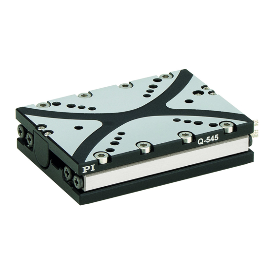
Q-545 Stage
User Manual
Version: 1.0.0
Date: 10.07.2015
This document describes the following
products:
Q-545
Q-Motion linear positioning stage,
piezoelectric inertia drive
This document applies to various model
versions of the Q-545. The model version of
the Q-545 is coded in the order number by
means of three characters after a period.
Meaning of the places and valid values:
First character after the period:
Travel range
1 = 13 mm
2 = 26 mm
Second character after the period:
Sensor equipment
0 = without sensor
4 = with sensor
Third character after the period:
Vacuum suitability
0 = suitable to 10
U = suitable to 10
PI miCos GmbH, Freiburger Strasse 30, 79427 Eschbach, Germany
Phone: +49 7634 5057-0, Fax: +49 7634 5057-99, E-mail: info@pimicos.com
-6
hPa
-9
hPa
Advertisement
Table of Contents

Related Manuals for PI Q-545


Summary of Contents for PI Q-545
- Page 1 This document applies to various model versions of the Q-545. The model version of the Q-545 is coded in the order number by means of three characters after a period. Meaning of the places and valid values:...
- Page 2 With regard thereto, Physik Instrumente (PI) GmbH & Co. KG retains all the rights. Use of said text, photographs and drawings is permitted only in part and only upon citation of the source.
-
Page 3: Table Of Contents
ID Chip ....................17 Unpacking Installation General Notes on Installation ................21 Mounting the Q-545 on a Surface and Connecting It to a Protective Earth Conductor ......................23 Setting Up a Multi-Axis System ................26 5.3.1 General Information on Setting Up a Multi-Axis System ....27 5.3.2... - Page 4 Start-Up and Operation General Notes on Start-Up and Operation ............47 Starting Up the stage ..................50 6.2.1 Starting Up the Q-545.x0x with the E-870 Drive Electronics ....51 6.2.2 Starting Up the Q-545.x4x with the E-871.1A1 Controller ....53 Maintenance General Notes on Maintenance ................55 Performing a Maintenance Run ................55...
- Page 5 Old Equipment Disposal EC Declaration of Conformity...
-
Page 7: About This Document
Downloading Manuals ....................3 1.1 Objective and Target Audience of this User Manual This manual contains information on the intended use of the Q-545. It assumes that the reader has a fundamental understanding of basic servo systems as well as motion control concepts and applicable safety procedures. -
Page 8: Definition
The linear encoder is an incremental sensor for capturing changes in position. Signals from the sensor are used for axis position feedback. After switching on the controller a reference point definition must be performed before absolute target positions can be commanded and reached. Version: 1.0.0 MP135E Q-545 Stage... -
Page 9: Figures
CD), access to the manuals is password-protected. The password is stored on the CD. Availability of the manuals: Password-protected manuals: FTP download directory Freely available manuals: PI website Follow the corresponding instructions for downloading. Q-545 Stage MP135E Version: 1.0.0... - Page 10 4. Find the user name and the password in the section "User login for software download" in the Release News. 5. Open the FTP download directory (ftp://pi-ftp.ws). − Windows operating systems: Open the FTP download directory in Windows Explorer.
-
Page 11: Safety
The Q-545 is built according to state-of-the-art technology and recognized safety standards. Improper use can result in personal injury and/or damage to the Q-545. Only use the Q-545 for its intended purpose, and only use it if it is in a good working order. -
Page 12: Organizational Measures
Add all information given by the manufacturer to the user manual, for example supplements or Technical Notes. If you pass the Q-545 on to other users, also include this user manual as well as other relevant information provided by the manufacturer. -
Page 13: Product Description
3.1 Model Overview Classification of the Q-545 models The model version of the Q-545 is coded in the order number by means of three characters after a period; see also "Detailed model names". Each character codes a feature of the model version:... - Page 14 Q-Motion Linear Stage, 26 mm Travel Range, Linear Encoder, 1 nm Resolution, 8 N Push / Pull Force, Dimensions 45 × 63 × 15 mm (W × L × H), Piezoelectric Inertia Drive, Vacuum-Compatible to 10 Version: 1.0.0 MP135E Q-545 Stage...
-
Page 15: Product View
3.2 Product View Figure 1: Example for models without sensor: Q-545.200 stage Moving platform Cable exit for drive connection Connection for drive; with Q-545.x00 models: Sub-D 15 (m) connector, with Q-545.x0U models: Sub-D 15 (f) connector Type plate p. 11 Base body... - Page 16 Moving platform Cable exit for drive connection Warning sign "Electrostatic sensitive devices" Connection for drive and sensor; with Q-545.x40 models: Sub-D 15 (m) connector, with Q-545.x4U models: Sub-D 15 (f) connector ESD protection: ESD protective cap with Q-545.x40; nonconductive foil with Q-545.x4U...
-
Page 17: Product Labeling
Figure 3: Direction of motion of the platform of the Q-545, Q-545.240 used as example The arrow in the figure above shows the direction of motion on positive commanding. 3.3 Product Labeling Figure 4: Example for models with sensor: Product labeling and type plate of the Q-545.240 stage Position Labeling... -
Page 18: Scope Of Delivery
Old equipment disposal WWW.PIMICOS.COM Manufacturer's address (website) 3.4 Scope of Delivery The Q-545 is delivered with the following components: Item ID Components Q-545 Linear positioning stage as specified in the order (p. 7) Screw set for mounting the Q-545, consisting of: ... -
Page 19: Accessories
Sub-D 15 (f) to Sub-D 15 (m), Air-side extension cable from vacuum feedthrough or Q-545.xx0 to E-873.UHV3 the adapter cable to the electronics, Sub-D 15 (f) to Sub-D 15 (m), For Q-545.xx0 models only (suitable for use in a vacuum to 10 hPa): Order... - Page 20 Aluminum (3.3206), anodized; mass: 49 g; includes: Q-145.200 2 dowel pins A2 2.5 m6 x 4 ISO 2338 4 socket head cap screws A2 M2.5x8 ISO 4762 For Q-545.xxU models only (suitable for use in a vacuum to 10 hPa): Order Description number Vacuum feedthrough (drive and sensor signals), Sub-D 15 (m/m), C-815.VFU1...
-
Page 21: Suitable Electronics
3 Product Description Order Description number Adapter bracket for vertical mounting of Q-545.2xU stages. Material: Aluminum (3.3206), uncoated; mass: 49 g; includes: Q-145.20U 2 dowel pins A2 2.5 m6 x 4 ISO 2338 4 socket head cap screws A2 M2.5x8 ISO 4762 ... -
Page 22: Technical Features
3.7 Technical Features 3.7.1 Linear Encoder (Sensor) Some of the Q-545 models are equipped with an optical linear encoder. For the encoder resolution, refer to the table in the "Specifications" section (p. 61). Optical linear encoders measure the actual position directly (direct metrology). -
Page 23: Id Chip
Settings for the sensor: Interpolation rate, corrections of hysteresis as well as of phase and offset, gain values When switched on or rebooted, controllers from PI read the data from the ID chip. For more information on the ID chip recognition, see the manual of the controller used. -
Page 25: Unpacking
NOTICE Electrostatic hazard Touching the pins in the Sub-D 15 connection of models equipped with sensor can damage electrostatic (also: ESD-) sensitive components of the Q-545. For this reason, these models are supplied with ESD protection: − Q-545.x40: ESD protection cap on the connector (m) −... -
Page 27: Installation
Installation In this Chapter General Notes on Installation ..................21 Mounting the Q-545 on a Surface and Connecting It to a Protective Earth Conductor ............................. 23 Setting Up a Multi-Axis System ................... 26 Affixing the Load to the Q-545 ..................35 Connecting the Q-545 to the Electronics .............. - Page 28 Install the Q-545 so that the application is not impaired by the dissipated heat. Ensure sufficient ventilation at the place of installation. Make sure that the complete bottom side of the Q-545 is in contact with the surface on which the Q-545 is mounted.
-
Page 29: Mounting The Q-545 On A Surface And Connecting It To A Protective Earth Conductor
NOTICE Warping of the Q-545 due to mounting on uneven surfaces! Mounting the Q-545 on an uneven surface can warp the Q-545. Warping reduces the accuracy. Mount the Q-545 on an even surface. The recommended evenness of the surface is ≤2 µm. - Page 30 Q-545 is mounted. The corresponding contact surfaces must be sufficiently conductive. The protective earth conductor is connected to the surface on which the Q-545 is mounted. The screws are secured against unintentional loosening; e.g., with threadlocker.
- Page 31 Introduce the two locating pins into the locating holes on the bottom side of the Q-545 (see figure above) or in the surface. b) Place the Q-545 on the surface so that the locating pins are inserted into the corresponding locating holes on the other side.
-
Page 32: Setting Up A Multi-Axis System
XY system (p. 27) Z system (p. 30) (XZ or XYZ combination) Figure 7: Example for an XYZ system: Three Q-545.140 mounted using an adapter bracket Lower stage Middle stage Q-145.1001 adapter bracket (use in a vacuum to 10... -
Page 33: General Information On Setting Up A Multi-Axis System
Only use screws and locating pins of the correct length for the respective holes. INFORMATION Any model of the Q-545 can be used as lower or upper stage. Designations in these instructions: Lower stage: Forms the basis of the multi-axis system (X axis); is mounted on a surface ... - Page 34 5 Installation Figure 8: Example: Mounting a Q-545.140 on a Q-545.140 Lower stage 2 dowel pins 2.5 m6 x 5 ISO 8734; for use as locating pins Upper stage 4 socket head cap screws M2.5x5 ISO 4762 Prerequisites You have read and understood the general notes on installation (p. 21).
- Page 35 1. Insert the two locating pins into the locating holes on the bottom side of the upper Q-545 or in the moving platform of the lower Q-545 (see figure above). 2. Place the upper Q-545 on the lower Q-545 so that the locating pins are inserted into the corresponding locating holes on the other side.
-
Page 36: Setting Up A Z System With An Adapter Bracket
NOTICE Inserting screws and locating pins too deeply! Screws and locating pins that are inserted too deeply damage the Q-545. Observe the depth of the mounting holes (p. 65) in the moving platform. Observe the maximum depth for the insertion of locating pins (p. 65) into the moving platform. - Page 37 Orientation of adapter bracket and upper stage to the lower stage: Combination of 0° 90° 180° 270° stages and adapter bracket: 2 Q-545.1xx + Q-145.1001 or Q-145.10U1 2 Q-545.2xx + Not possible. The Not possible. The moving platforms of moving platforms of...
- Page 38 Mounting accessories from the scope of delivery of the stage (p. 12): − 2 dowel pins 2.5 m6 x 5, for use as locating pins − 4 socket head cap screws M2.5x5 Allen wrench AF 2 Version: 1.0.0 MP135E Q-545 Stage...
- Page 39 5 Installation Figure 9: Example: Setting up an XZ system consisting of two Q-545.140 and a Q-145.200 or Q-145.20U adapter bracket Lower stage 2 dowel pins 2.5 m6 x 4 for use as locating pins; from the scope of delivery of the adapter bracket Q-145.200 adapter bracket (for operation in a vacuum to 10...
- Page 40 2. Mount the short side of the adapter bracket to the moving platform of the lower stage: a) Insert the 2.5 m6 x 4 locating pins into the locating holes in the short side of the adapter bracket from below and up to the limit stop (see figure above). Version: 1.0.0 MP135E Q-545 Stage...
-
Page 41: Affixing The Load To The Q-545
NOTICE Screws and locating pins that are too long! Screws and locating pins that are inserted too deeply damage the Q-545. Observe the depth of the mounting holes (p. 65) in the moving platform. Observe the maximum depth for the insertion of locating pins (p. 65) into the moving platform. - Page 42 5 Installation Figure 11: Q-545.14x The arrows mark the following mounting holes in the moving platform of the Q-545.1xx: For aligning the load: White arrows: Locating holes Ø 2.5 mm H7, depth 2.5 mm For affixing the load: Dark-gray arrows: M2.5 threaded holes, depth 5 mm...
- Page 43 Ø 2.5 mm H7 Affixing the load to the Q-545 1. Align the load on the Q-545 so that the mounting holes in the load and the holes in the moving platform overlap. If you use locating pins to align the load: a) Insert the locating pins into the locating holes in the moving platform or in the load.
-
Page 44: Connecting The Q-545 To The Electronics
5 Installation 5.5 Connecting the Q-545 to the Electronics The electronics to be used for operating the Q-545 depends on the presence of a sensor (see also "Suitable Electronics" (p. 15)): Models without sensor (Q-545.x0x): E-870 drive electronics (p. 38) ... - Page 45 Connecting the Q-545.x0x to E-870 drive electronics with Mini-DIN 4 socket for operation at atmospheric pressure Figure 13: Connection diagram for Q-545.x00 and drive electronics with Mini-DIN 4 socket, for operation at atmospheric pressure Drive electronics with Mini-DIN 4 socket (here E-870.xG) 7202500042-0015 adapter cable Q-545.x00...
- Page 46 Connecting the Q-545.x0x to E-870 drive electronics with Mini-DIN 4 socket for operation in a vacuum Figure 15: Connection diagram for Q-545.x00 and drive electronics with Mini-DIN 4 socket, for operation in a vacuum to 10 Drive electronics with Mini-DIN socket (here E-870.xG) 7202500042-0015 adapter cable E-873.UHVx extension cable...
- Page 47 5 Installation Figure 16: Connection diagram for Q-545.x0U and drive electronics with Mini-DIN 4 socket, for operation in a vacuum to 10 Drive electronics with Mini-DIN socket (here E-870.xG) 7202500042-0015 adapter cable E-873.UHVx extension cable C-815.VFUx vacuum feedthrough (here C-815.VFU1) Q-545.x0U...
-
Page 48: Connecting The Q-545 To The Controller
5 Installation If a Q-545.x0x is to be operated in a vacuum: 1. Follow the instructions in "Connecting the Q-545.x0x to E-870 drive electronics with Mini-DIN 4 socket for operation in a vacuum" to install the vacuum feedthrough and to connect the stage, vacuum feedthrough, and cables. - Page 49 5 Installation Connecting the Q-545.x4x to the E-871 controller for operation at atmospheric pressure Figure 17: Connection diagram for Q-545.x40 and controller, for operation at atmospheric pressure Controller (here E-871.1A1) 7202500043-0015 Y adapter cable Q-545.x40 Figure 18: Connection diagram for Q-545.x4U and controller, for operation at atmospheric pressure Controller (here E-871.1A1)
- Page 50 5. Secure the connections with the integrated screws against accidental disconnection. Connecting the Q-545.x4x to the E-871 controller for operation in a vacuum Figure 19: Connection diagram for Q-545.x40 and controller, for operation in a vacuum to 10 Controller (here E-871.1A1) 7202500043-0015 Y adapter cable E-873.UHVx extension cable C-815.VF vacuum feedthrough...
- Page 51 5 Installation Figure 20: Connection diagram for Q-545.x4U and controller, for operation in a vacuum to 10 Controller (here E-871.1A1) 7202500043-0015 Y adapter cable E-873.UHVx extension cable C-815.VFUx vacuum feedthrough (here C-815.VFU1) Q-545.x4U 1. Before connecting for the first time: Install the vacuum feedthrough: a) Obtain the dimensions from the corresponding dimensional drawing (p.
-
Page 53: Start-Up And Operation
If a protective earth conductor is not or not properly connected, dangerous touch voltages can occur on the Q-545 in the case of malfunction or failure of the system. If touch voltages exist, touching the Q-545 can result in minor injuries from electric shock. - Page 54 An operating frequency that is too high can cause damage to the Q-545. Only operate the Q-545 with controllers/drivers and original accessories from PI. Do not exceed the operating frequency range (p. 63) for which the Q-545 is specified.
- Page 55 Q-545. Only operate the Q-545 with controllers/drivers and original accessories from PI. Do not exceed the operating voltage range (p. 63) for which the Q-545 is specified. Only operate the Q-545 when the operating voltage is properly connected; see "Pin Assignment"...
-
Page 56: Starting Up The Stage
If possible: Select another part of the travel range for the working range in regular intervals. 6.2 Starting Up the Stage The electronics to be used for operating the Q-545 depends on the presence of a sensor (see also "Suitable Electronics" (p. 15)): ... -
Page 57: Starting Up The Q-545.X0X With The E-870 Drive Electronics
The PIShift drive develops noises in step mode. The noise development depends on the current step frequency. 6.2.1 Starting Up the Q-545.x0x with the E-870 Drive Electronics INFORMATION The values for the parameters of the E-870 drive electronics are listed in a table in this section. - Page 58 ID 0x1F000500 the output of one period of the modified sawtooth signal in step mode Number of steps the PIShift Steps per Second 20000 stage moves per ID 0x1F000600 second at the set operating frequency. Version: 1.0.0 MP135E Q-545 Stage...
-
Page 59: Starting Up The Q-545.X4X With The E-871.1A1 Controller
PIMicosStages2.dat stage database. The entries in the stage database are updated regularly. Download the PI Update Finder from the PI website (http://www.update.pi- portal.ws) and use it to update the PIMicosStages2.dat stage database on your For further information, see the user manual of the E-871 controller. - Page 60 2. If necessary: Adapt the Maximum Motor Output (ID 0x9) parameter to your application (also refer to "General Notes on Start-Up and Operation" (p. 47) and "Operating Time" (p. 64)). The E-871 user manual describes the start-up using the PIMikroMove program. Version: 1.0.0 MP135E Q-545 Stage...
-
Page 61: Maintenance
7.1 General Notes on Maintenance NOTICE Damage due to improper maintenance! Improper maintenance can lead to misalignment and failure of the Q-545. Only loosen screws according to the instructions in this manual. 7.2 Performing a Maintenance Run The maintenance run must cover the entire travel range. -
Page 63: Troubleshooting
(for details, see "Starting Up the Stage" (p. 50) and mode manual of the electronics used). Mount the Q-545 on an even surface. The Warped base body recommended evenness of the surface is 2 µm. Q-545 Stage MP135E Version: 1.0.0... - Page 64 Keep the distance between the center of gravity of the load and the center of the moving platform as small as possible in all directions. Only operate the Q-545 in a clean environment and Unsuitable ambient conditions within the permissible ambient conditions (p. 63).
-
Page 65: Customer Service
9 Customer Service Customer Service For inquiries and orders, contact your PI sales engineer or send us an e-mail (info@pi.ws). If you have questions concerning your system, have the following information ready: − Product codes and serial numbers of all products in the system −... -
Page 67: Technical Data
10 Technical Data In this Chapter Specifications ......................61 Operating Time ......................64 Dimensions ........................65 Pin Assignment ......................76 10.1 Specifications 10.1.1 Data Table Preliminary Data Q-545.100 / Q-545.140 / Q-545.200 / Q-545.240 / Unit Tolerance Q-545.10U Q-545.14U Q-545.20U Q-545.24U... - Page 68 Sub-D 15 Sub-D 15 Recommended E-870 E-871, E-873 E-870 E-871, E-873 controller / driver The Q-545 stage series replaces the LPS-45 series. The specifications were determined on a surface with an evenness of 2 µm. Version: 1.0.0 MP135E Q-545 Stage...
-
Page 69: Maximum Ratings
48 V 20 kHz 30 W 10.1.3 Ambient Conditions and Classifications The following ambient conditions and classifications must be observed for the Q-545: Area of application For indoor use only Maximum altitude 2000 m Air pressure Q-545.xx0: 1100 hPa to 10 Q-545.xxU:... -
Page 70: Operating Time
60 s (max.) ≤ 1000 120 s (max.) For the relevant parameters, see "Starting Up the Stage" (p. 50) and the user manual of the electronics used. With 100 % duty cycle without heat dissipation Version: 1.0.0 MP135E Q-545 Stage... -
Page 71: Dimensions
10 Technical Data 10.3 Dimensions 10.3.1 Q-545.10x Dimensions in mm Characters used to separate decimal places: Depth and diameter of holes: Period All other dimensions: Comma Figure 21: Q-545.10x Q-545 Stage MP135E Version: 1.0.0... -
Page 72: Q-545.14X
10 Technical Data 10.3.2 Q-545.14x Dimensions in mm Characters used to separate decimal places: Depth and diameter of holes: Period All other dimensions: Comma Figure 22: Q-545.14x Version: 1.0.0 MP135E Q-545 Stage... -
Page 73: Q-545.20X
10 Technical Data 10.3.3 Q-545.20x Dimensions in mm Characters used to separate decimal places: Depth and diameter of holes: Period All other dimensions: Comma Figure 23: Q-545.20x Q-545 Stage MP135E Version: 1.0.0... -
Page 74: Q-545.24X
10 Technical Data 10.3.4 Q-545.24x Dimensions in mm Characters used to separate decimal places: Depth and diameter of holes: Period All other dimensions: Comma Figure 24: Q-545.24x Version: 1.0.0 MP135E Q-545 Stage... -
Page 75: Q-145.1001 And Q-145.10U1 Adapter Brackets
10.3.5 Q-145.1001 and Q-145.10U1 Adapter Brackets Dimensions in mm. Note that the decimal places are separated by a comma in the drawings. Figure 25: Q-145.1001 adapter bracket, dimensions of the Q-145.10U1 adapter bracket are identical Q-545 Stage MP135E Version: 1.0.0... -
Page 76: Q-145.200 And Q-145.20U Adapter Brackets
10.3.6 Q-145.200 and Q-145.20U Adapter Brackets Dimensions in mm. Note that the decimal places are separated by a comma in the drawings. Figure 26: Q-145.200 adapter bracket, dimensions of the Q-145.20U adapter bracket are identical Version: 1.0.0 MP135E Q-545 Stage... -
Page 77: Vacuum Feedthroughs
C-815.VFU6 (p. 74) C-815.VFU15 (p. 75) C-815.VF vacuum feedthrough for 10 Dimensions in mm. Note that the decimal places are separated by a comma in the drawings. Figure 27: C-815.VF vacuum feedthrough Sub-D 15 (m/f) Q-545 Stage MP135E Version: 1.0.0... - Page 78 10 Technical Data C-815.VFU1 vacuum feedthrough for 10 Dimensions in mm. Note that the decimal places are separated by a comma in the drawings. Figure 28: C-815.VFU1 vacuum feedthrough, Sub-D 15 (m/m) Vacuum side Air side Version: 1.0.0 MP135E Q-545 Stage...
- Page 79 10 Technical Data C-815.VFU3 vacuum feedthrough for 10 Dimensions in mm. Note that the decimal places are separated by a comma in the drawings. Figure 29: C-815.VFU3 vacuum feedthrough, Sub-D 15 (m/m) Vacuum side Air side Q-545 Stage MP135E Version: 1.0.0...
- Page 80 10 Technical Data C-815.VFU6 vacuum feedthrough for 10 Dimensions in mm. Note that the decimal places are separated by a comma in the drawings. Figure 30: C-815.VFU6 vacuum feedthrough, Sub-D 15 (m/m) Vacuum side Air side Version: 1.0.0 MP135E Q-545 Stage...
- Page 81 10 Technical Data C-815.VFU15 vacuum feedthrough for 10 Dimensions in mm. Note that the decimal places are separated by a comma in the drawings. Figure 31: C-815.VFU15 vacuum feedthrough, Sub-D 15 (m/m) Vacuum side Air side Q-545 Stage MP135E Version: 1.0.0...
-
Page 82: Pin Assignment
10 Technical Data 10.4 Pin Assignment 10.4.1 Q-545.xx0 Connector: Sub-D 15 (m) The Sub-D 15 (m) connector transmits the signals of the drive and, for the models with sensor, in addition the signals of the sensor and of the ID chip. -
Page 83: Q-545.Xxu
Only for models with sensor. Not assigned for models without sensor. The cable shield is connected to the connector shell. 10.4.2 Q-545.xxU Connector: Sub-D 15 (f) The Sub-D 15 (f) connector transmits the signals of the drive and, for the models with sensor, in addition the signals of the sensor and of the ID chip. -
Page 84: C-815.Vf Vacuum Feedthrough
Only for models with sensor. Not assigned for models without sensor. The cable shield is connected to the connector shell. 10.4.3 C-815.VF Vacuum Feedthrough Sub-D 15 (m/f) Figure 34: Vacuum side: Sub-D 15 (f) socket Figure 35: Air side: Sub-D 15 (m) panel plug Version: 1.0.0 MP135E Q-545 Stage... - Page 85 Encoder A (-) COS - Encoder B (-) Motor (-) Motor signal differential (-) Motor (+) Motor signal differential (+) REF + Reference signal differential (+) SIN + Encoder A (+) COS + Encoder B (+) Q-545 Stage MP135E Version: 1.0.0...
-
Page 86: C-815.Vfux Vacuum Feedthrough
Air side Signal Function COS - Encoder B (-) SIN - Encoder A (-) ID chip data ID chip data Supply voltage (+5 V) Motor (+) Motor signal differential (+) Motor (-) Motor signal differential (-) Version: 1.0.0 MP135E Q-545 Stage... -
Page 87: 5604500041 Adapter
Motor (-) Motor signal differential (-) 10.4.5 5604500041 Adapter Sub-D 15 (m/m) The adapter is only required if a Q-545.xxU model is to be operated at atmospheric pressure (i.e., without a vacuum feedthrough). Figure 38: Sub-D 15 (m) connector Q-545 Stage MP135E Version: 1.0.0... - Page 88 10 Technical Data Figure 39: Pin assignment of the 5604500041 adapter Version: 1.0.0 MP135E Q-545 Stage...
- Page 89 PI miCos equipment made available on the market after 13 August 2005 without charge. Any old PI miCos equipment can be sent free of charge to the following address: PI miCos GmbH Freiburger Strasse 30...
- Page 91 12 EC Declaration of Conformity 12 EC Declaration of Conformity For the Q-545, an EC Declaration of Conformity has been issued in accordance with the following European directives: 2006/95/EC, Low Voltage Directive 2004/108/EC, EMC Directive 2011/65/EU, RoHS Directive The applied standards certifying the conformity are listed below.
Need help?
Do you have a question about the Q-545 and is the answer not in the manual?
Questions and answers