PI H-811 User Manual
Hexapod microrobot
Hide thumbs
Also See for H-811:
- User manual (110 pages) ,
- Short instructions (8 pages) ,
- User manual (93 pages)
Table of Contents
Advertisement
Quick Links
MS235E
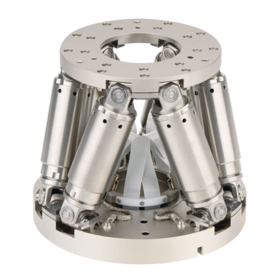
H-811 Hexapod Microrobot
User Manual
Version: 3.0.0
Physik Instrumente (PI) GmbH & Co. KG, Auf der Römerstraße 1, 76228 Karlsruhe, Germany
Phone +49 721 4846-0, fax +49 721 4846-1019, e-mail info@pi.ws, www.pi.ws
Date: 08/19/2024
This document describes the following products:
H-811.I2
Miniature hexapod microrobot, brushless DC
motor, 5 kg load capacity, 20 mm/s max.
velocity
H-811.I2V
Miniature hexapod microrobot, brushless DC
motor, vacuum compatible to 10
load capacity, 10 mm/s velocity
H-811.F2
Miniature hexapod microrobot for optical
alignment, removable magnetic plate,
brushless DC motor, 5 kg load capacity, 20
mm/s max. velocity
H-811.S2
Miniature hexapod microrobot for high
dynamics applications, direct drive, 2.5 kg load
capacity, 25 mm/s maximum velocity
hPa, 5 kg
-6
Advertisement
Table of Contents

Related Manuals for PI H-811


Summary of Contents for PI H-811
- Page 1 Miniature hexapod microrobot for high dynamics applications, direct drive, 2.5 kg load capacity, 25 mm/s maximum velocity Physik Instrumente (PI) GmbH & Co. KG, Auf der Römerstraße 1, 76228 Karlsruhe, Germany Phone +49 721 4846-0, fax +49 721 4846-1019, e-mail info@pi.ws, www.pi.ws...
- Page 2 BiSS is a registered trademark of iC-Haus GmbH. © 2024 Physik Instrumente (PI) GmbH & Co. KG, Karlsruhe, Germany. The text, photographs, and drawings in this manual are protected by copyright. With regard thereto, Physik Instrumente (PI) GmbH & Co. KG retains all the rights.
-
Page 3: Table Of Contents
Contents About this Document Objective and Target Group of this User Manual ............1 Symbols and Typographic Conventions..............1 Figures ........................2 Other Applicable Documents ..................2 Downloading Manuals ....................2 Safety Intended Use ......................5 General Safety Instructions ..................5 Organizational Measures .................... - Page 4 10.1.3 Specifications for Data Transmission and Power Supply Cables ....59 10.2 Maximum Ratings ..................... 61 10.3 Ambient Conditions and Classifications ..............62 10.4 Dimensions ....................... 63 10.4.1 H-811 Hexapod .................... 63 10.4.2 000067899 Connector Holder ..............67 10.5 Load Curves ......................68 10.6 Dynamic Working Range ..................80 10.7 Pin Assignment ......................
-
Page 5: About This Document
About this Document Objective and Target Group of this User Manual This user manual contains the information necessary for using the H-811 as intended. We assume that the user has basic knowledge of closed-loop systems, motion control concepts, and applicable safety measures. -
Page 6: Figures
Photographic illustrations may also differ and must not be seen as guaranteed properties. Other Applicable Documents The devices and software tools from PI mentioned in this documentation are described in separate manuals. Device / program... - Page 7 5. For the desired manual, select ADD TO LIST and then REQUEST. 6. Fill out the request form and select SEND REQUEST. The download link will be sent to the email address entered in the form. H-811 Hexapod Microrobot MS235E Version: 3.0.0...
-
Page 9: Safety
Add all information from the manufacturer such as supplements or technical notes to the user manual. If you give the H-811 to other users, include this user manual as well as all other relevant information provided by the manufacturer. -
Page 10: Measures For Handling Vacuum-Compatible Products
2 Safety Personnel qualification The H-811 may only be installed, started, operated, maintained, and cleaned by authorized and appropriately qualified personnel. Measures for Handling Vacuum-Compatible Products When handling the vacuum model of the hexapod, attention must be paid to appropriate cleanliness. -
Page 11: Product Description
H-811.I2V Miniature hexapod microrobot; brushless DC motor; vacuum compatible to 10-6hPa; 5 kg load capacity; 10 mm/s velocity; 2 m cable length (vacuum side); feedthroughs Product View Figure 1: Elements of H-811.I2 and H-811.S2 H-811 Hexapod Microrobot MS235E Version: 3.0.0... - Page 12 3 Product Description Figure 2: Elements of the H-811.I2V Motion platform Strut Base plate Data transmission cable Power supply cable Figure 3: Elements of the H-811.F2 Motion platform Version: 3.0.0 MS235E H-811 Hexapod Microrobot...
-
Page 13: Technical Features
3.3.3 Controller The hexapod is intended for operation with a suitable controller from PI (p. 16). With the controller, it is possible to command motion of individual axes, combinations of axes or all six axes at the same time in a single motion command. -
Page 14: Motion
The following is a description of how the hexapod behaves with the default coordinate system. Work with user-defined coordinate systems is described in the C887T0007 User Manual. Version: 3.0.0 MS235E H-811 Hexapod Microrobot... - Page 15 A specified rotation in space is calculated from the individual rotations in the order U -> V- > W. For further information on the center of rotation, refer to the glossary (p. 91). H-811 Hexapod Microrobot MS235E Version: 3.0.0...
- Page 16 1. The U axis is commanded to move to position 10. The rotation around the U axis tilts the rotational axes V and W. Platform in reference position Platform position: U = 10 (U parallel to spatially fixed Xaxis) Version: 3.0.0 MS235E H-811 Hexapod Microrobot...
- Page 17 Platform position: U = 10, V = –10, W = 10 (U and V parallel to the platform level, W vertical to the platform level) For further data on the travel ranges, refer to the "Specifications" (p. 49) section. H-811 Hexapod Microrobot MS235E Version: 3.0.0...
-
Page 18: Id Chip
(e.g., geometry data and control parameters). The configuration data for customized hexapods is only stored on the controller if the hexapod and controller are delivered together, or if PI was correspondingly informed before delivery of the controller. -
Page 19: Optional Accessories
2 socket head screws, M6×30 ISO 4762 1 hex key 5.0 DIN 911 Note that the cables required for connecting the H-811 to the electronics must be ordered separately. Optional Accessories Order number Data transmission cable, available lengths C-815.82D02... -
Page 20: Suitable Controllers
Available for hexapod mechanics H-811.F2 and H-811.I2 in combination with a C-887 hexapod controller that features a high-resolution analog input. Installation is done by a PI service engineer in a remote session. Contact will be established by PI after purchase. - Page 21 EtherCAT interface, motion stop 6-axis controller for hexapods, TCP/IP, RS-232, benchtop device, incl. C-887.533 control of two additional axes, EtherCAT interface, motion stop, analog inputs To order, contact our customer service department (p. 47). H-811 Hexapod Microrobot MS235E Version: 3.0.0...
-
Page 23: Unpacking
When handling the vacuum model of the hexapod, attention must be paid to appropriate cleanliness. At PI, all parts are cleaned before assembly. Powder-free gloves are worn during assembly and measuring. In addition, the hexapod is wipe cleaned afterwards and then shrink- wrapped twice in vacuum-compatible film. -
Page 25: Installing
Make sure that no collisions between the hexapod, the load to be moved, and the surroundings are possible in the workspace of the hexapod. H-811 Hexapod Microrobot MS235E Version: 3.0.0... -
Page 26: Determining Valid Poses
The load of the hexapod struts varies depending on the following factors: Activation state of the servo mode in the controller Installation position of the hexapod Load to be moved: mass and position of the center of mass on the motion platform Version: 3.0.0 MS235E H-811 Hexapod Microrobot... -
Page 27: Grounding The Hexapod
− The cable is not subject to tensile stress. − The cable is not moved. Fix the permanently installed data transmission cable with the supplied connector holder (p. 14) to underlying surface. H-811 Hexapod Microrobot MS235E Version: 3.0.0... - Page 28 3. Fix the connector holder onto the underlying surface with the screws supplied. The free side of the connector holder is intended for the connection of a suitable data transmission cable. Refer to "Connecting the Hexapod to the Controller" (p. 28) for further information. Version: 3.0.0 MS235E H-811 Hexapod Microrobot...
-
Page 29: Mounting The Hexapod On A Surface
Put the hexapod onto the surface so that the locating pins are inserted into the corresponding locating holes in the hexapod's base plate. 3. Mount the hexapod on the three mounting holes in the base plate with the included screws. H-811 Hexapod Microrobot MS235E Version: 3.0.0... -
Page 30: Fixing The Load To The Hexapod
Only mount the hexapod and the load on the mounting fixtures (holes) intended for this purpose. INFORMATION H-811.F2 model only: The load to be aligned can be fixed to the mounting plate or directly to the motion platform. Fixing to the mounting plate is recommended. - Page 31 Optional: Two Ø 3 mm m6 locating pins for easy alignment of the load on the hexapod, not included in the scope of delivery H-811.F2 model only: If you want to fix several loads to be aligned in quick succession: one additional mounting plate each per assembly, available as optional accessory (p.
-
Page 32: Connecting The Hexapod To The Controller
(see figure). Connecting the Hexapod to the Controller Cables with a length of 0.5 m (H-811.I2., .F2, .S2) or 2 m (811.I2V) are installed permanently on the hexapod. Connecting cables are not included in the scope of delivery and must be ordered separately (p. - Page 33 If you want to operate a vacuum-compatible hexapod in a vacuum chamber: Suitable tools for installing the vacuum feedthrough If necessary: Installing vacuum feedthroughs Figure 7: Vacuum feedthrough for data transmission (4668), dimensions in mm 4 holes, Ø6 x 45° for M3 countersunk screw H-811 Hexapod Microrobot MS235E Version: 3.0.0...
- Page 34 Pay attention to the assignment specified on the labeling of the sockets, plug − connectors, and cables. − Pay attention to the mechanical coding of connectors and sockets. − Do not use force. Use the integrated screws to secure the connections against accidental − disconnection. Version: 3.0.0 MS235E H-811 Hexapod Microrobot...
- Page 35 Panel plug / connector, male Socket / connector, female Controller Refer to "Suitable Controllers (p. 16)" Hexapod H-811.x2 Power adapter, from the scope of delivery of the controller, 24 V DC output Data transmission cable Power supply cable H-811 Hexapod Microrobot MS235E Version: 3.0.0...
- Page 36 Hexapod H-811.I2V Power adapter, from the scope of delivery of the controller, 24 V DC output Vacuum chamber Data transmission cable Power supply cable Vacuum feedthrough for data transmission Vacuum feedthrough for power supply Version: 3.0.0 MS235E H-811 Hexapod Microrobot...
-
Page 37: Startup
Do not place any objects in areas where they can be caught by moving parts. Only command valid poses. See "Determining Valid Poses" (p. 22) for the definition of a valid pose. Stop the motion immediately if a controller malfunction occurs. H-811 Hexapod Microrobot MS235E Version: 3.0.0... -
Page 38: Starting Up The Hexapod System
Starting up the hexapod system 1. Start up the controller (refer to the user manual of the controller). 2. Run a few motion cycles for test purposes (refer to the user manual of the controller). Version: 3.0.0 MS235E H-811 Hexapod Microrobot... -
Page 39: Optional: Operating The Hexapod With A Separate 12 V Power Adapter
TCP/IP interface or the RS-232 interface. d) Send the following commands to adapt the controller's settings permanently to the 12 V power adapter of the hexapod and to reboot the controller: SVO X 0 CCL 1 advanced H-811 Hexapod Microrobot MS235E Version: 3.0.0... - Page 40 2. Disconnect the hexapod from the C-501.12060M12 power adapter. 3. Switch the controller on. 4. Use PITerminal to establish communication between the controller and the PC via the TCP/IP interface or the RS-232 interface. Version: 3.0.0 MS235E H-811 Hexapod Microrobot...
- Page 41 8. If there is an M12 plug screw, remove it from the controller's 24 V output (24 V Out 7 9. Connect the hexapod to the 24 V output of the controller. For further information, refer to "Connecting the Hexapod to the Controller" (p. 28). H-811 Hexapod Microrobot MS235E Version: 3.0.0...
-
Page 43: Maintenance
7 Maintenance Maintenance PI offers a range of wraparound services for all their products, many of which are designed to increase the system’s lifetime and uptime: Remote system setup: An expert ensures that your system is optimized and runs ... -
Page 44: Packing The Hexapod For Transport
2. Uninstall the hexapod system: a) Remove the load from the motion platform of the hexapod. b) Switch the controller off. c) Remove the data transmission cable and the power supply cable from the controller. Version: 3.0.0 MS235E H-811 Hexapod Microrobot... - Page 45 (e.g., connector holder (p. 23)). e) Remove the hexapod from the surface. Packing the hexapod Proceed as described in H811T0001 (in the scope of delivery (p. 14)). H-811 Hexapod Microrobot MS235E Version: 3.0.0...
-
Page 47: Troubleshooting
Carry out a tuning of the parameters. Unsuitable control parameters for the Contact our customer service department (p. 47). application The system behavior has changed due to an increasing ease of operation. H-811 Hexapod Microrobot MS235E Version: 3.0.0... - Page 48 Check the Power Good signal and the activation state of the 24-V output for the hexapod (24 V Out 7 A). Options: − In PIMikroMove, open the Diagnostic Information window by selecting the C-887 > Show diagnostic Version: 3.0.0 MS235E H-811 Hexapod Microrobot...
- Page 49 1. Send the ERR? command and check the error code that is located at a position returned. outside the travel range limits. Commanding a 2. Send the POS? command to check the current position of permitted target position H-811 Hexapod Microrobot MS235E Version: 3.0.0...
- Page 50 not move" section applies to your problem. possible If the problem with your hexapod is not listed in the table or cannot be solved as described, contact our customer service department (p. 47). Version: 3.0.0 MS235E H-811 Hexapod Microrobot...
-
Page 51: Customer Service Department
9 Customer Service Department Customer Service Department For inquiries and orders, contact your PI representative or send us an email (mailto:service@pi.de). If you have questions concerning your system, provide the following information: − Product and serial numbers of all products in the system Firmware version of the controller (if applicable) −... -
Page 53: Technical Data
250 mrad/s Typical angular velocity in θY 250 mrad/s Typical angular velocity in θZ 250 mrad/s Positioning H-811.I2 Tolerance Minimum incremental motion in X 0.2 µm typ. Minimum incremental motion in Y 0.2 µm typ. H-811 Hexapod Microrobot MS235E Version: 3.0.0... - Page 54 Maximum load capacity, base plate 5 kg horizontal Maximum holding force, base plate in any 2.5 N orientation Maximum holding force, base plate 15 N horizontal Overall mass 2.2 kg Material Stainless steel, aluminum Version: 3.0.0 MS235E H-811 Hexapod Microrobot...
- Page 55 10 mm/s Typical angular velocity in θX 250 mrad/s Typical angular velocity in θY 250 mrad/s Typical angular velocity in θZ 250 mrad/s Amplitude-frequency product in X 11.99 mm·Hz Amplitude-frequency product in Y 10.88 mm·Hz H-811 Hexapod Microrobot MS235E Version: 3.0.0...
- Page 56 Backlash in Y 0.5 µm typ. Backlash in Z 0.15 µm typ. Backlash in θX 5 µrad typ. Backlash in θY 5 µrad typ. Backlash in θZ 10 µrad typ. Integrated sensor Incremental rotary encoder Version: 3.0.0 MS235E H-811 Hexapod Microrobot...
- Page 57 4.95 mm Minimum bending radius for fixed 25 mm installation, power supply Outer diameter data transmission cable 9.5 mm Minimum bending radius for fixed 95 mm installation, data transmission Recommended controllers / drivers C-887.5x H-811 Hexapod Microrobot MS235E Version: 3.0.0...
- Page 58 ± 0.06 µm typ. Unidirectional repeatability in θX ± 2 µrad typ. Unidirectional repeatability in θY ± 2 µrad typ. Unidirectional repeatability in θZ ± 3 µrad typ. Backlash in X 0.2 µm typ. Version: 3.0.0 MS235E H-811 Hexapod Microrobot...
- Page 59 Outer diameter power supply cable 4.95 mm Minimum bending radius for fixed 25 mm installation, power supply Outer diameter data transmission cable 9.5 mm Minimum bending radius for fixed 95 mm installation, data transmission H-811 Hexapod Microrobot MS235E Version: 3.0.0...
- Page 60 H-811.F2: Scanning times: typical time span for scanning the entire area and moving to the highest intensity H-811.F2: The specified values for maximum payload and maximum holding force apply to the hexapod without the removable magnetic plate. The cables fixed to the H-811 are 0.5 m long respectively.
- Page 61 2.5 N orientation Maximum holding force, base plate 15 N horizontal Overall mass 2.2 kg Material Stainless steel, aluminum Miscellaneous H-811.I2V Tolerance Operating temperature range 0 to 50 °C Vacuum class 10⁻⁶ ǀ hPa H-811 Hexapod Microrobot MS235E Version: 3.0.0...
-
Page 62: Specifications For Vacuum-Compatible Models
0,0,0. At PI, technical data is specified at 22 ±3 °C. Unless otherwise stated, the values are for unloaded conditions. Some properties are interdependent. The designation "typ." indicates a statistical average for a property; it does not indicate a guaranteed value for every product supplied. During the final inspection of a product, only selected properties are analyzed, not all. -
Page 63: Specifications For Data Transmission And Power Supply Cables
Data Transmission and Power Supply Cables Data transmission Power supply cable, single-side Power supply cable, straight cable angled connector connectors All hexapod types H-820, H-824, H-825, H-840, H-850 H-810, H-811, H-206 C-815.82D02 C-815.82P02A C-815.82P02E H-811 Hexapod Microrobot MS235E Version: 3.0.0... - Page 64 General Unit Cable length L 2 / 3 / 5 / 7.5 / 10 / 20 Maximum velocity Maximum acceleration Maximum number of bending cycles 1 million Operating temperature range -10 to +70 °C Version: 3.0.0 MS235E H-811 Hexapod Microrobot...
-
Page 65: Maximum Ratings
Cables longer that 20 m require additional power drivers. 10.2 Maximum Ratings The hexapod is designed for the following operating data: Maximum Maximum Maximum operating current operating frequency consumptio voltage (unloaded) 24 V DC H-811 Hexapod Microrobot MS235E Version: 3.0.0... -
Page 66: Ambient Conditions And Classifications
Highest relative humidity of 80% at temperatures of up to 31°C, decreasing linearly to a relative humidity of 50% at 40°C Degree of protection according IP20 to IEC 60529 Area of application For indoor use only Maximum altitude 2000 m Version: 3.0.0 MS235E H-811 Hexapod Microrobot... -
Page 67: Dimensions
10 Technical Data 10.4 Dimensions 10.4.1 H-811 Hexapod Dimensions in mm. Note that a comma is used in the drawings instead of a decimal point. Figure 11: H-811.I2, at zero position of nominal travel range H-811 Hexapod Microrobot MS235E Version: 3.0.0... - Page 68 10 Technical Data Figure 12: H-811.S2, at zero position of nominal travel range Version: 3.0.0 MS235E H-811 Hexapod Microrobot...
- Page 69 10 Technical Data Figure 13: H-811.F2, at zero position of nominal travel range H-811 Hexapod Microrobot MS235E Version: 3.0.0...
- Page 70 10 Technical Data Figure 14: H-811.I2V, at zero position of nominal travel range If the controller's factory settings are used for the coordinate system and the center of rotation, the hexapod in the figure corresponds to the position X=Y=Z=U=V=W=0. The (0,0,0) coordinates indicate the origin of the coordinate system. When the default settings for the coordinate system and center of rotation are used, and the hexapod is at position X=Y=Z=U=V=W=0, the center of rotation is at the origin of the coordinate system.
-
Page 71: 000067899 Connector Holder
10 Technical Data 10.4.2 000067899 Connector Holder Dimensions in mm. Note that the decimal points are separated by a comma in the drawings. Figure 15: 000067899 connector holder for strain relief H-811 Hexapod Microrobot MS235E Version: 3.0.0... -
Page 72: Load Curves
Load Curves The load curves in the following figures only apply when the hexapod is connected to the controller and the servo mode is switched on. Figure 16: Maximum loads on the H-811.I2 when mounted horizontally Version: 3.0.0 MS235E H-811 Hexapod Microrobot... - Page 73 10 Technical Data Figure 17: Maximum loads on the H-811.I2 when mounted vertically H-811 Hexapod Microrobot MS235E Version: 3.0.0...
- Page 74 10 Technical Data Figure 18: Maximum loads on the H-811.I2 when mounted at the most unfavorable angle Version: 3.0.0 MS235E H-811 Hexapod Microrobot...
- Page 75 10 Technical Data Figure 19: Maximum permissible force acting on the H-811.I2 when mounted horizontally H-811 Hexapod Microrobot MS235E Version: 3.0.0...
- Page 76 10 Technical Data Figure 20: Maximum loads on the H-811.I2V when mounted horizontally Version: 3.0.0 MS235E H-811 Hexapod Microrobot...
- Page 77 10 Technical Data Figure 21: Maximum loads on the H-811.I2V when mounted vertically H-811 Hexapod Microrobot MS235E Version: 3.0.0...
- Page 78 10 Technical Data Figure 22: Maximum loads on the H-811.I2V when mounted at the most unfavorable angle Version: 3.0.0 MS235E H-811 Hexapod Microrobot...
- Page 79 10 Technical Data Figure 23: Maximum permissible force acting on the H-811.I2V when mounted horizontally H-811 Hexapod Microrobot MS235E Version: 3.0.0...
- Page 80 10 Technical Data Figure 24: Maximum loads on the H-811.F2 when mounted horizontally Version: 3.0.0 MS235E H-811 Hexapod Microrobot...
- Page 81 10 Technical Data Figure 25: Maximum loads on the H-811.F2 when mounted vertically H-811 Hexapod Microrobot MS235E Version: 3.0.0...
- Page 82 10 Technical Data Figure 26: Maximum loads on the H-811.F2 when mounted at the most unfavorable angle Version: 3.0.0 MS235E H-811 Hexapod Microrobot...
- Page 83 10 Technical Data Figure 27: Maximum permissible force acting on the H-811.F2 when mounted horizontally H-811 Hexapod Microrobot MS235E Version: 3.0.0...
-
Page 84: Dynamic Working Range
10 Technical Data 10.6 Dynamic Working Range The diagrams mark the dynamic working range of the H-811.S2. Here, the following prerequisites apply: A compact load is mounted centrically. The base plate of the hexapod is in the horizontal mounting position. - Page 85 10 Technical Data Figure 29: Dynamic working range of the H-811.S2, Y, 2.5 kg H-811 Hexapod Microrobot MS235E Version: 3.0.0...
- Page 86 10 Technical Data Figure 30: Dynamic working range of the H-811.S2, Z, 2.5 kg Version: 3.0.0 MS235E H-811 Hexapod Microrobot...
- Page 87 10 Technical Data Figure 31: Dynamic working range of the H-811.S2, U (ƟX), 2.5 kg H-811 Hexapod Microrobot MS235E Version: 3.0.0...
- Page 88 10 Technical Data Figure 32: Dynamic working range of the H-811.S2, V (ƟY), 2.5 kg Version: 3.0.0 MS235E H-811 Hexapod Microrobot...
- Page 89 10 Technical Data Figure 33: Dynamic working range of the H-811.S2, W (ƟZ), 2.5 kg H-811 Hexapod Microrobot MS235E Version: 3.0.0...
-
Page 90: Pin Assignment
Not for vacuum models: Power supply via 4-pin M12 connector Function 24 V DC 24 V DC Only for vacuum models: Power supply via 2-pin LEMO panel plug, male, type ECJ.1B.302.CLD Function 24 V DC Version: 3.0.0 MS235E H-811 Hexapod Microrobot... -
Page 91: Data Transmission Connector
CH3 Ref OUT CH3 LimP OUT CH3 LimN OUT CH3 A+ OUT CH3 B+ OUT CH3 A- OUT CH3 B- OUT CH4 Sign IN CH4 MAGN IN CH4 Ref OUT CH4 LimP OUT CH4 LimN OUT H-811 Hexapod Microrobot MS235E Version: 3.0.0... - Page 92 CH6 MAGN IN CH6 Ref OUT CH6 LimP OUT CH6 LimN OUT CH6 A+ OUT CH6 B+ OUT CH6 A- OUT CH6 B- OUT ID Chip Brake/Enable drive 24 V input Power Good 24 V output Version: 3.0.0 MS235E H-811 Hexapod Microrobot...
-
Page 93: Old Equipment Disposal
PI equipment made available on the market after 13 August 2005 without charge. If you have an old device from PI, you can send it to the following address free of charge: Physik Instrumente (PI) GmbH & Co. KG... -
Page 95: Glossary
The center of rotation that can be moved using the SPI command is also referred to as "pivot point". Hexapod system The combination of hexapod, controller, cables, and power adapter(s) is referred to as "hexapod system" in this manual. H-811 Hexapod Microrobot MS235E Version: 3.0.0... - Page 96 The Z axis is perpendicular to the base plate of the hexapod. The following example figures of the H-810 hexapod show that the coordinate system does not move along with motion of the platform. Version: 3.0.0 MS235E H-811 Hexapod Microrobot...
- Page 97 12 Glossary Figure 34: H-810 hexapod in the reference position. Cable exit H-811 Hexapod Microrobot MS235E Version: 3.0.0...
- Page 98 12 Glossary Figure 35: H-810 hexapod, the platform of which has been moved in X. Cable exit Version: 3.0.0 MS235E H-811 Hexapod Microrobot...
-
Page 99: Appendix
The following test cycles are performed: Motion over the entire travel range with at least 20 measuring points, in at least five cycles. Motion over partial sections, e.g., ±1 mm in increments of for example, 100 µm H-811 Hexapod Microrobot MS235E Version: 3.0.0... -
Page 100: European Declarations Of Conformity
13 Appendix 13.2 European Declarations of Conformity For the H-811, declarations of conformity were issued according to the following European statutory requirements: EMC Directive RoHS Directive The standards applied for certifying conformity are listed below. EMC: EN 61326-1 Safety: EN 61010-1 RoHS: EN IEC 63000 Version: 3.0.0...
Need help?
Do you have a question about the H-811 and is the answer not in the manual?
Questions and answers