Table of Contents
Advertisement
Quick Links
MS202E
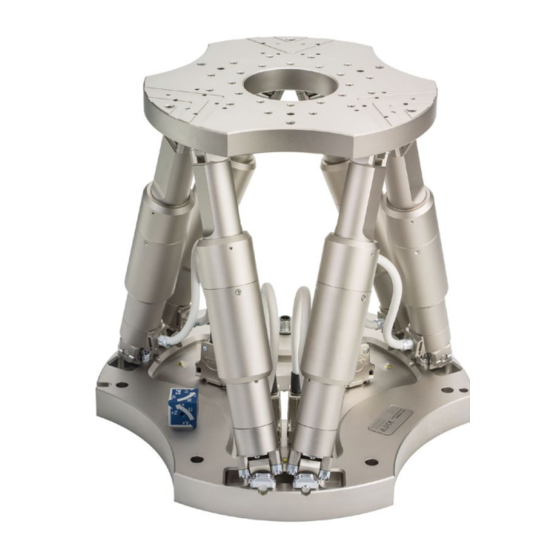
H-850 Hexapod Microrobot
User Manual
Version: 2.4.0
Physik Instrumente (PI) GmbH & Co. KG, Auf der Roemerstrasse 1, 76228 Karlsruhe, Germany
Phone +49 721 4846-0, Fax +49 721 4846-1019, Email info@pi.ws, www.pi.ws
Date: 21.07.2022
This document describes the following hexapod
microrobots:
H-850.H2A
H-850.H2V
H-850.G2A
H-850.G2V
Advertisement
Table of Contents

Related Manuals for PI H-850


Summary of Contents for PI H-850
- Page 1 This document describes the following hexapod microrobots: H-850.H2A H-850.H2V H-850.G2A H-850.G2V Physik Instrumente (PI) GmbH & Co. KG, Auf der Roemerstrasse 1, 76228 Karlsruhe, Germany Phone +49 721 4846-0, Fax +49 721 4846-1019, Email info@pi.ws, www.pi.ws...
- Page 2 BiSS is a registered trademark of iC-Haus GmbH. © 2022 Physik Instrumente (PI) GmbH & Co. KG, Karlsruhe, Germany. The text, photographs, and drawings in this manual are protected by copyright. With regard thereto, Physik Instrumente (PI) GmbH & Co. KG retains all the rights.
-
Page 3: Table Of Contents
Unpacking Unpacking the Hexapod ................... 19 Removing the Transport Safeguard................20 4.2.1 Removing the Transport Safeguard for the H-850.x2V Models ....20 4.2.2 Removing the Transport Safeguard for the H-850.x2A Models ....21 Installation General Notes on Installing ..................23 Determining the Permissible Load and Workspace .......... - Page 4 Optional: Removing the Coordinate Cube ............... 28 Connecting the Hexapod to the Controller .............. 29 Startup General Notes on Startup ..................33 Starting Up the Hexapod System ................34 Baking Out Vacuum-Compatible Models ..............35 Maintenance Performing a Maintenance Run ................37 Packing the Hexapod for Transport ................
-
Page 5: About This Document
Downloading Manuals ........................3 Objective and Target Audience of this User Manual This manual contains information on using the H-850 as intended. It assumes that the reader has a fundamental understanding of basic servo systems as well as motion control concepts and applicable safety procedures. -
Page 6: Figures
For better understandability, the colors, proportions, and degree of detail in illustrations can deviate from the actual circumstances. Photographic illustrations may also differ and must not be seen as guaranteed properties. Other Applicable Documents The devices and software tools from PI mentioned in this documentation are described in separate manuals. Device/program Document Document content C-887.5xx controller... -
Page 7: Downloading Manuals
If a manual is missing or problems occur with downloading: Contact our customer service department (p. 53). Downloading Manuals 1. Open the website www.pi.ws. 2. Search the website for the product number (e.g., P-882) or the product family (e.g., PICMA® bender). -
Page 9: Safety
The H-850 is built according to state-of-the-art technology and recognized safety standards. Improper use can result in personal injury and/or damage to the H-850. Use the H-850 for its intended purpose only, and only when it is in perfect technical condition. -
Page 10: Measures For Handling Vacuum-Compatible Products
2 Safety If you give the H-850 to a third party, include this user manual as well as other relevant information provided by the manufacturer. Do the work only if the user manual is complete. Missing information due to an incomplete user manual can result in minor injury and damage to equipment. -
Page 11: Product Description
Technical Features ........................11 Features and Applications The various models (p. 7) of H-850 hexapod that are offered differ with respect to the sensor type, the maximum velocity, and load capacity as well as suitability for use in a vacuum. -
Page 12: Suitable Controllers
EtherCAT interface, motion stop C-887.533 6-axis controller for hexapods, TCP/IP, RS-232, benchtop device, incl. control of two additional axes, EtherCAT interface, motion stop, analog inputs To order, contact our customer service department (p. 53). Version: 2.4.0 MS202E H-850 Hexapod Microrobot... -
Page 13: Product View
Components H-850 Hexapod according to your order (p. 7) Note that the cables required for connecting the H-850 to the electronics must be ordered separately. For the H-850.H2V and H-850.G2V vacuum-compatible models, a 2 m cable set for the vacuum side is included in the scope of delivery. - Page 14 2 flat washers, form A-4.3 DIN 7090 2 lock washers, Schnorr Ø 4 mm N0110 Note that the cables required for connecting the H-850 to the electronics must be ordered separately: Order number Data transmission cable, available lengths C-815.82D02...
-
Page 15: Technical Features
Reference and limit switches Joints for connecting to the base plate and motion platform The actuator contains the following components: H-850.G2V, .H2V: DC motor with incremental rotary encoder H-850.G2A, .H2A: Brushless DC motor, absolute-measuring encoder Gearhead ... -
Page 16: Control
3.6.3 Control Der hexapod is intended for operation with a suitable controller from PI (p. 8). The controller makes it possible to command motion of individual axes, combinations of axes or all six axes at the same time in a single motion command. - Page 17 Translation Translations are described in the spatially-fixed coordinate system. The translational axes X, Y, and Z meet at the origin of the coordinate system (0,0,0). For further information, see the glossary (p. 79). H-850 Hexapod Microrobot MS202E Version: 2.4.0...
- Page 18 For further information on the center of rotation, see the glossary (p. 79). INFORMATION The dimensional drawing (p. 68) contains the following: Orientation of the default coordinate system Position of the default center of rotation Version: 2.4.0 MS202E H-850 Hexapod Microrobot...
- Page 19 The rotation around the U axis tilts the rotational axes V and W. Figure 3: Rotation around the U axis Platform in reference position Platform position: U = 10 (U parallel to spatially-fixed X axis) H-850 Hexapod Microrobot MS202E Version: 2.4.0...
- Page 20 The rotation around the V axis tilts the rotational axes U and W. Figure 4: Rotation around the V axis Platform in reference position Platform position: U = 10, V = –10 (U and V parallel to the platform level) Version: 2.4.0 MS202E H-850 Hexapod Microrobot...
-
Page 21: Id Chip
(e.g., geometry data and control parameters). The configuration data for customized hexapods is only stored on the controller if the hexapod and controller are delivered together, or if PI was correspondingly informed before delivery of the controller. - Page 22 3 Product Description Version: 2.4.0 MS202E H-850 Hexapod Microrobot...
-
Page 23: Unpacking
6. Compare the contents with the items listed in the contract and the packing list. If any of the parts are wrong or are missing, contact PI immediately. 7. Inspect the hexapod for signs of damage. If there is any sign of damage, contact PI immediately. -
Page 24: Removing The Transport Safeguard
8. Remove the transport safeguard according to the instructions (p. 20) that apply to your hexapod model. Removing the Transport Safeguard 4.2.1 Removing the Transport Safeguard for the H-850.x2V Models Figure 6: Transport safeguard components Hexapod with transport safeguard attached... -
Page 25: Removing The Transport Safeguard For The H-850.X2A Models
4 Unpacking 4.2.2 Removing the Transport Safeguard for the H-850.x2A Models Figure 1: Transport safeguard components Cover M6x16 screw M8 nut Strut Tools and accessories Open-end wrench AF 10 Open-end wrench AF 13 Removing the transport safeguard 1. Loosen the 4 nuts (M8) used for securing the transport safeguard's cover to the struts. - Page 26 4 Unpacking 7. Keep the transport safeguard as well as all screws, flat washers, and nuts in case the product needs to be transported later. Version: 2.4.0 MS202E H-850 Hexapod Microrobot...
-
Page 27: Installation
Make sure that no collisions between the hexapod, the load to be moved, and the surroundings are possible in the workspace of the hexapod. H-850 Hexapod Microrobot MS202E Version: 2.4.0... -
Page 28: Determining The Permissible Load And Workspace
PIVeriMove, see the C887T0002 technical note (in the scope of delivery of the software). Determining the Permissible Load and Workspace Tools and Accessories PC with Windows operating system with the PI Hexapod Simulation Tool installed. For further information, see the A000T0068 technical note. -
Page 29: Grounding The Hexapod
Use one of the mounting holes in the motion platform (p. 68) for connection. If the motion platform and the load are connected conductively to each other, − connect the load to the grounding system. H-850 Hexapod Microrobot MS202E Version: 2.4.0... -
Page 30: Mounting The Hexapod On A Surface
Place the hexapod on the surface so that the locating pins are inserted into the corresponding locating holes on the other side. 3. Mount the hexapod on the six mounting holes in the base plate using the included screws. Version: 2.4.0 MS202E H-850 Hexapod Microrobot... -
Page 31: Fixing The Load To The Hexapod
Tools and accessories Screws of suitable length. For model-dependent options, see dimensional drawing (p. 68): M4 screws − − M6 screws − M8 screws Suitable tool for tightening the screws H-850 Hexapod Microrobot MS202E Version: 2.4.0... -
Page 32: Optional: Removing The Coordinate Cube
Tools and accessories Hex key AF 2.0 Removing the coordinate cube Figure 7: Removing the Coordinate Cube 1. Loosen the threaded pin M4x8. 2. Pull the coordinate cube upwards away from the base plate. Version: 2.4.0 MS202E H-850 Hexapod Microrobot... -
Page 33: Connecting The Hexapod To The Controller
If you want to operate a vacuum-compatible hexapod in a vacuum chamber: Suitable tools for installing the vacuum feedthrough If necessary: Installing vacuum feedthroughs Figure 8: Vacuum feedthrough for data transmission (4668), dimensions in mm 4 holes, Ø6 x 45° for M3 countersunk screw H-850 Hexapod Microrobot MS202E Version: 2.4.0... - Page 34 Pay attention to the assignment specified on the labeling of the sockets, plug − connectors, and cables. − Pay attention to the mechanical coding of connectors and sockets. − Do not use force. Use the integrated screws to secure the connections against accidental − disconnection. Version: 2.4.0 MS202E H-850 Hexapod Microrobot...
- Page 35 Controller Refer to "Suitable Controllers" (p. 8) Hexapod H-850.H2A, .G2A Power adapter, from the scope of delivery of the controller, 24 V DC output Data transmission cable* Power supply cable* * Must be ordered separately. H-850 Hexapod Microrobot MS202E Version: 2.4.0...
- Page 36 Panel plug / connector, male Socket / connector, female Controlle Refer to "Suitable Controllers" (p. 8) Hexapod H-850.H2V, .G2V Power adapter, from the scope of delivery of the controller, 24 V DC output Vacuum chamber Data transmission cable* Power supply cable*...
-
Page 37: Startup
Once you have established communication via TCP/IP or RS-232, send the CST? command. The response shows the hexapod, to which the controller is adapted. Only operate the hexapod with a controller whose configuration data is adapted to the hexapod. H-850 Hexapod Microrobot MS202E Version: 2.4.0... -
Page 38: Starting Up The Hexapod System
Starting up the hexapod system 1. Start up the controller (refer to the user manual of the controller). 2. Run a few motion cycles for test purposes (refer to the user manual of the controller). Version: 2.4.0 MS202E H-850 Hexapod Microrobot... -
Page 39: Baking Out Vacuum-Compatible Models
Perform a maintenance run over the entire travel range during the bakeout and cooling process at least once a day. For details on the maintenance run procedure, see the user manual of the controller. H-850 Hexapod Microrobot MS202E Version: 2.4.0... -
Page 41: Maintenance
Packing the Hexapod for Transport ..................... 38 Cleaning the Hexapod ........................46 PI offers a range of wraparound services for all their products, many of which are designed to increase the system’s lifetime and uptime: Remote system setup: An expert ensures that your system is optimized and runs ... -
Page 42: Packing The Hexapod For Transport
Only hold the hexapod by the transport safeguard or the base plate. INFORMATION The figures in the instructions for the H-850.x2V models show an H-840 hexapod. The transport safeguard for the H-840 is attached the same way as the H-850. - Page 43 (2) and the base plate of the hexapod (see figures in "Removing the Transport Safeguard for the H-850.x2V Models" (p. 20)). If the hexapod system is defective, the holes in the hexapod and transport safeguard may not be in line because the hexapod has not reached the transport position.
- Page 44 4. Fasten the transport safeguard with 4 screws (M6x20) on the side of the base plate (see figure). Attaching the transport safeguard for the H-850.x2A models 1. Command a hexapod motion to the transport position: X = Y = Z = U = V = W = 0 2.
- Page 45 Tighten the struts by hand. Securing nuts and flat washers: a) Screw an M8 nut onto each strut up to the end of the thread. b) Put an 8.4 flat washer onto each nut. H-850 Hexapod Microrobot MS202E Version: 2.4.0...
- Page 46 6.4 flat washer onto. Attaching the cover to the struts: a) Push an 8.4 flat washer onto each strut. b) Screw an M8 nut onto each strut and tighten by hand. Version: 2.4.0 MS202E H-850 Hexapod Microrobot...
-
Page 47: Packing The Hexapod
Place the foam insert for the hexapod's base plate into the inner box. Pay attention to the appropriate orientation of the insert. 4. Grip the hexapod's transport safeguard or base plate and place it into the foam insert of the inner box. H-850 Hexapod Microrobot MS202E Version: 2.4.0... - Page 48 11. Wrap the box and pallet with stretch film to protect them against moisture, see figure. Step 3 a Step 3 b Step 3 e The appropriate orientation of the foam insert depends on the hexapod model. Version: 2.4.0 MS202E H-850 Hexapod Microrobot...
- Page 49 Step 6 Only necessary when a cushion made of folded corrugated cardboard is part of the original packaging. Step 8 Step 9 Step 11 The upper box contains the controller. H-850 Hexapod Microrobot MS202E Version: 2.4.0...
-
Page 50: Cleaning The Hexapod
If necessary, clean the surfaces of the hexapod with a cloth that is dampened with a mild cleanser or disinfectant. Only when the hexapod is used in vacuum: Touch the hexapod only with powder-free gloves. If necessary, wipe the hexapod clean. Version: 2.4.0 MS202E H-850 Hexapod Microrobot... -
Page 51: Troubleshooting
Carry out a tuning of the Unsuitable control bad. parameters. parameters for the application Contact our customer service department (p. 53). The system behavior has changed due to an increasing ease of operation. H-850 Hexapod Microrobot MS202E Version: 2.4.0... - Page 52 = 1 - 24-V output of the C- − 887.5xx controller is active = 0 - 24-V output of the C- − 887.5xx controllers is inactive For further information, refer to the user manual for the C-887.5xx controller. Version: 2.4.0 MS202E H-850 Hexapod Microrobot...
- Page 53 2. Send the ERR? command and check the error code that is returned. For details on possible error codes and their causes, see "Protective Functions of the C-887" in the user manual of the C-887.5xx controller. H-850 Hexapod Microrobot MS202E Version: 2.4.0...
- Page 54 = 1 - 24-V output of the C- 887.5xx controller is active = 0 - 24-V output of the C- − 887.5xx controllers is inactive For further information, refer to the user manual for the C-887.5xx controller. Version: 2.4.0 MS202E H-850 Hexapod Microrobot...
- Page 55 If the hexapod does not have an ID chip, you must load the suitable configuration manually if needed. For further information, refer to the user manual for the C-887.5xx controller. H-850 Hexapod Microrobot MS202E Version: 2.4.0...
- Page 56 If the problem with your hexapod is not listed in the table or cannot be solved as described, contact our customer service department (p. 53). Version: 2.4.0 MS202E H-850 Hexapod Microrobot...
-
Page 57: Customer Service
9 Customer Service Customer Service For inquiries and orders, contact your PI sales engineer or send us an email (mailto:service@pi.de). If you have any questions concerning your system, provide the following information: Product and serial numbers of all products in the system −... -
Page 59: Technical Data
± 15 ° ± 15 ° in θY Rotation range ± 30 ° ± 30 ° in θZ Maximum 8 mm/s 0.5 mm/s velocity in X, unloaded Maximum 8 mm/s 0.5 mm/s velocity in Y, unloaded H-850 Hexapod Microrobot MS202E Version: 2.4.0... - Page 60 Absolute rotary encoder, sensor turn multi-turn Unidirectional ± 0.5 µm ± 0.6 µm typ. repeatability in Unidirectional ± 0.5 µm ± 0.6 µm typ. repeatability in Unidirectional ± 0.2 µm ± 0.2 µm typ. repeatability in Version: 2.4.0 MS202E H-850 Hexapod Microrobot...
- Page 61 7.5 µrad typ. Backlash in θY 25 µrad 7.5 µrad typ. Backlash in θZ 90 µrad 60 µrad typ. Drive H-850.G2A H-850.H2A Tolerance properties Drive type Brushless DC gear motor Brushless DC gear motor H-850 Hexapod Microrobot MS202E Version: 2.4.0...
- Page 62 The travel ranges of the individual coordinates (X, Y, Z, θX, θY, θZ) are interdependent. The data for each axis in this table shows its maximum travel range, where all other axes and the pivot point are at the reference position. Connecting cables are not in the scope of delivery and must be ordered separately. Version: 2.4.0 MS202E H-850 Hexapod Microrobot...
-
Page 63: Specifications For Vacuum-Compatible Versions
1.8 mrad/s angular velocity in θZ, unloaded Typical velocity 2 mm/s 0.1 mm/s in X, unloaded Typical velocity 2 mm/s 0.1 mm/s in Y, unloaded Typical velocity 2 mm/s 0.1 mm/s in Z, unloaded H-850 Hexapod Microrobot MS202E Version: 2.4.0... - Page 64 Typ. repeatability in θZ Minimum 1 µm 0.3 µm Typ. incremental motion in X 1 µm 0.3 µm Typ. Minimum incremental motion in Y Minimum 0.5 µm 0.2 µm Typ. incremental motion in Z Version: 2.4.0 MS202E H-850 Hexapod Microrobot...
- Page 65 Stiffness in Y 7 N/µm 7 N/µm Stiffness in Z 100 N/µm 100 N/µm Maximum 85 N 500 N holding force, passive, any orientation Maximum 250 N 2000 N holding force, passive, horizontal orientation H-850 Hexapod Microrobot MS202E Version: 2.4.0...
- Page 66 Air side connecting cables are not included in the scope of delivery and must be ordered separately. Drive and sensor Motor Manufacturer: Faulhaber Motor type: DC, 2342S024 Version: 2.4.0 MS202E H-850 Hexapod Microrobot...
-
Page 67: Maximum Ratings
10 Technical Data Gearhead HDUC–8-100 Harmonic Drive for H-850.H2V CS-8-50 Harmonic Drive for H-850.G2V Encoder Manufacturer: Faulhaber Encoder type: magnetic encoder, IE2-512 Reference Switch Optical, vacuum-compatible Materials used Machine-made parts >95% of the machine-made parts, i.e. base plate, struts, motion platform: AlMgSi (3.2315) chemically nickel-plated, AlMg4.5Mn (3.3547),... -
Page 68: Specifications For Data Transmission And Power Supply Cables
Connector type (power supply A – Angled connector cable only) E – Straight connector General Unit Cable length L 2 / 3 / 5 / 7.5 / 10 / 20 Maximum velocity Maximum acceleration Version: 2.4.0 MS202E H-850 Hexapod Microrobot... - Page 69 Minimum bending radius with the fixed installation Outer diameter Connector M12 m/f Data transmission Unit cable Minimum bending radius in a drag chain Minimum bending radius with the fixed installation H-850 Hexapod Microrobot MS202E Version: 2.4.0...
-
Page 70: Specifications For Data Transmission And Power Supply Cables For Vacuum
The following table lists the technical data of the data transmission and power supply cables. Model Overview Data transmission Data transmission Power supply cable, Power supply cable, cable cable, installed angled connector installed permanently permanently H-850.x2V, H-824.x2V H-811.I2V H-850.x2V, H-824.x2V H-811.I2V K040B0254 K040B0507 K060B0132 K060B0330 General Unit Cable length L Operating -10 to +80 °C... -
Page 71: Ambient Conditions And Classifications
0 °C to 70 °C Bakeout temperature Vacuum-compatible models only: 80 °C (176 °F) Humidity: Highest relative humidity of 80% at temperatures of up to 31°C, decreasing linearly to a relative humidity of 50% at 40°C H-850 Hexapod Microrobot MS202E Version: 2.4.0... -
Page 72: Dimensions
The (0,0,0) coordinates indicate the origin of the coordinate system. The center of rotation is at the origin of the coordinate system when the default settings for the coordinate system and center of rotation are used, and the hexapod is at position X=Y=Z=U=V=W=0. Version: 2.4.0 MS202E H-850 Hexapod Microrobot... - Page 73 10 Technical Data Figure 2: H-850.x2A, dimensions in mm, at the zero position of the nominal travel range H-850 Hexapod Microrobot MS202E Version: 2.4.0...
-
Page 74: Load Curves
10 Technical Data 10.6 Load Curves Figure 3: Maximum loads of the H-850.G2A when mounted horizontally Figure 4: Maximum loads on the H-850.G2A when mounted vertically Version: 2.4.0 MS202E H-850 Hexapod Microrobot... - Page 75 10 Technical Data Figure 5: Maximum loads on the H-850.G2A when mounted at the most unfavorable angle Figure 6: Maximum permissible force acting on the H-850.G2A when mounted horizontally H-850 Hexapod Microrobot MS202E Version: 2.4.0...
- Page 76 10 Technical Data Figure 7: Maximum loads of the H-850.H2A when mounted horizontally Figure 8: Maximum loads on the H-850.H2A when mounted vertically Version: 2.4.0 MS202E H-850 Hexapod Microrobot...
- Page 77 10 Technical Data Figure 9: Maximum loads on the H-850.H2A when mounted at the most unfavorable angle Figure 10: Maximum permissible force acting on the H-850.H2A when mounted horizontally H-850 Hexapod Microrobot MS202E Version: 2.4.0...
-
Page 78: Pin Assignment
2-pin LEMO panel plug, male, type ECJ.1B.302.CLD Function 24 V DC 10.7.2 Data Transmission Connection Data transmission between hexapod and controller Panel plug HD Sub-D 78 m Function All signals: TTL Version: 2.4.0 MS202E H-850 Hexapod Microrobot... - Page 79 CH4 B+ OUT CH4 A- OUT CH4 B- OUT CH5 Sign IN CH5 MAGN IN CH5 Ref OUT CH5 LimP OUT CH5 LimN OUT CH5 A+ OUT CH5 B+ OUT CH5 A- OUT CH5 B- OUT H-850 Hexapod Microrobot MS202E Version: 2.4.0...
- Page 80 CH6 MAGN IN CH6 Ref OUT CH6 LimP OUT CH6 LimN OUT CH6 A+ OUT CH6 B+ OUT CH6 A- OUT CH6 B- OUT ID Chip Brake/Enable drive 24 V input Power Good 24 V output Version: 2.4.0 MS202E H-850 Hexapod Microrobot...
-
Page 81: Old Equipment Disposal
Dispose of your old equipment according to international, national, and local rules and regulations. In order to fulfill its responsibility as the product manufacturer, Physik Instrumente (PI) GmbH & Co. KG undertakes environmentally correct disposal of all old PI equipment made available on the market after 13 August 2005 without charge. -
Page 83: Glossary
The X, Y, and Z axes of the Cartesian coordinate system are always spatially fixed, i.e., the coordinate system does not move when the platform of the hexapod moves. The X, Y and Z axes are also referred to as translational axes. H-850 Hexapod Microrobot MS202E Version: 2.4.0... - Page 84 The Z axis is perpendicular to the base plate of the hexapod. The following example figures of the H-810 hexapod show that the coordinate system does not move along with motion of the platform. Figure 14: H-810 hexapod in the reference position. Cable exit Version: 2.4.0 MS202E H-850 Hexapod Microrobot...
- Page 85 12 Glossary Figure 15: H-810 hexapod, the platform of which has been moved in X. Cable exit H-850 Hexapod Microrobot MS202E Version: 2.4.0...
-
Page 87: Appendix
The following test cycles are performed: Motion over the entire travel range with at least 20 measuring points, in at least five cycles. Motion over partial sections, e.g., ±1 mm in increments of for example, 100 µm H-850 Hexapod Microrobot MS202E Version: 2.4.0... -
Page 89: European Declarations Of Conformity
13 Appendix 13.2 European Declarations of Conformity For the H-850, declarations of conformity were issued according to the following European statutory requirements: EMC Directive RoHS Directive The applied standards certifying the conformity are listed below. EMC: EN 61326-1 Safety: EN 61010-1...
Need help?
Do you have a question about the H-850 and is the answer not in the manual?
Questions and answers