Table of Contents
Advertisement
Quick Links
MS201E
H-840 Hexapod Microrobot
User manual
Version: 2.5.1
Physik Instrumente (PI) GmbH & Co. KG, Auf der Roemerstrasse 1, 76228 Karlsruhe, Germany
Phone +49 721 4846-0, Fax +49 721 4846-1019, Email info@pi.ws, www.pi.ws
Date: 20.09.2022
This document describes the following hexapod
microrobots:
H-840.G2A
H-840.G2I
H-840.G2IHP
H-840.D2A
H-840.D2I
Advertisement
Table of Contents

Subscribe to Our Youtube Channel
Related Manuals for PI H-840 Series


Summary of Contents for PI H-840 Series
- Page 1 This document describes the following hexapod microrobots: H-840.G2A H-840.G2I H-840.G2IHP H-840.D2A H-840.D2I Physik Instrumente (PI) GmbH & Co. KG, Auf der Roemerstrasse 1, 76228 Karlsruhe, Germany Phone +49 721 4846-0, Fax +49 721 4846-1019, Email info@pi.ws, www.pi.ws...
- Page 2 BiSS is a registered trademark of iC-Haus GmbH. © 2022 Physik Instrumente (PI) GmbH & Co. KG, Karlsruhe, Germany. The text, photographs, and drawings in this manual are protected by copyright. With regard thereto, Physik Instrumente (PI) GmbH & Co. KG retains all the rights.
-
Page 3: Table Of Contents
Contents About this Document Objective and Target Audience of this User Manual..........1 Symbols and Typographic Conventions..............1 Figures ........................2 Other Applicable Documents ..................2 Downloading Manuals ....................3 Safety Intended Use ......................5 General Safety Instructions ..................5 Organizational Measures .................... - Page 4 Startup General Notes on Startup ..................31 Starting Up the Hexapod System ................32 Maintenance Performing a Maintenance Run ................33 Packing the Hexapod for Transport ................34 7.2.1 Attaching the Transport Safeguard ............. 34 7.2.2 Packing the Hexapod ................... 37 Cleaning the Hexapod ....................
-
Page 5: About This Document
1 About this Document About this Document Objective and Target Audience of this User Manual This manual contains information on using the H-840 as intended. It assumes that the reader has a fundamental understanding of basic servo systems as well as motion control concepts and applicable safety procedures. -
Page 6: Figures
For better understandability, the colors, proportions, and degree of detail in illustrations can deviate from the actual circumstances. Photographic illustrations may also differ and must not be seen as guaranteed properties. Other Applicable Documents The devices and software tools from PI mentioned in this documentation are described in separate manuals. Device/program Document Document content C-887.5xx controller... -
Page 7: Downloading Manuals
If a manual is missing or problems occur with downloading: Contact our customer service department (p. 45). Downloading Manuals 1. Open the website www.pi.ws. 2. Search the website for the product number (e.g., P-882). 3. Click the corresponding product to open the product detail page. -
Page 9: Safety
The hexapod can only be used as intended in conjunction with a suitable controller available from PI (p. 8), which coordinates all motion of the hexapod. General Safety Instructions The H-840 is built according to state-of-the-art technology and recognized safety standards. - Page 10 2 Safety Install and operate the H-840 only after you have read and understood this user manual. Personnel qualification The H-840 may only be installed, started, operated, maintained, and cleaned by authorized and appropriately qualified personnel. Version: 2.5.1 MS201E H-840 Hexapod Microrobot...
-
Page 11: Product Description
No accumulation of errors of individual axes No friction and torques from moving cables The hexapod is controlled with a controller that can be ordered separately from PI (p. 8). The position commands to the controller are entered as Cartesian coordinates. Model Overview Model Designation H-840.G2A... -
Page 12: Suitable Controllers
3 Product Description Suitable Controllers Model Description C-887.52 6-axis controller for hexapods, TCP/IP, RS-232, benchtop device, incl. control of two additional axes C-887.521 6-axis controller for hexapods, TCP/IP, RS-232, benchtop device, incl. control of two additional axes, analog inputs 6-axis controller for hexapods, TCP/IP, RS-232, benchtop device, incl. C-887.522 control of two additional axes, motion stop C-887.523... -
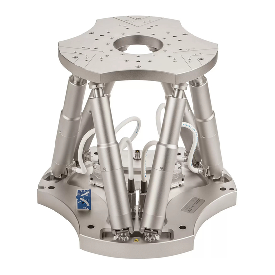
Page 13: Product View
3 Product Description Product View Figure 1: Elements of the H-840 Motion platform Strut Coordinate cube Panel plug for power supply cable Panel plug for data transmission cable Base plate Scope of Delivery Order number Components H-840 Hexapod according to your order (p. 7) Packaging, consisting of: Transport safeguard with mounting kit ... - Page 14 3 Product Description Order number Components Documentation, consisting of: H840T0001 Technical note on unpacking the hexapod MS247EK Short instructions for hexapod systems Screw sets and tools: 000034605 Mounting kit: 6 socket head screws, M6×30 ISO 4762 1 hex key 5.0 DIN 911 ...
-
Page 15: Technical Features
3.6.3 Control Der hexapod is intended for operation with a suitable controller from PI (p. 8). The controller makes it possible to command motion of individual axes, combinations of axes or all six axes at the same time in a single motion command. -
Page 16: Motion
3 Product Description The controller calculates the settings for the individual struts from the target positions given for the translational and rotational axes. The velocities and accelerations of the struts are calculated so that all struts start and stop at the same time. Every time the controller of a hexapod equipped with incremental encoders is switched on or rebooted, the hexapod must complete a reference move, in which each strut moves to its reference switch. - Page 17 3 Product Description Figure 2: Coordinate system and rotations to the rotational coordinates U, V, and W. The coordinate system is depicted above the platform for better clarity Translation Translations are described in the spatially-fixed coordinate system. The translational axes X, Y, and Z meet at the origin of the coordinate system (0,0,0).
- Page 18 3 Product Description Rotation Rotations take place around the rotational axes U, V, and W. The rotational axes meet at the center of rotation (also referred to as "pivot point"). The rotational axes and therefore also the center of rotation always move together with the platform of the hexapod (see also the example below for consecutive rotations).
- Page 19 3 Product Description 1. The U axis is commanded to move to position 10. The rotation around the U axis tilts the rotational axes V and W. Figure 3: Rotation around the U axis Platform in reference position Platform position: U = 10 (U parallel to spatially-fixed X axis) H-840 Hexapod Microrobot MS201E Version: 2.5.1...
- Page 20 3 Product Description 1. The V axis is commanded to move to position –10. The rotation takes place around rotational axis V, which was tilted during the previous rotation. The rotation around the V axis tilts the rotational axes U and W. Figure 4: Rotation around the V axis Platform in reference position Platform position: U = 10, V = –10 (U and V parallel to the platform level)
-
Page 21: Id Chip
(e.g., geometry data and control parameters). The configuration data for customized hexapods is only stored on the controller if the hexapod and controller are delivered together, or if PI was correspondingly informed before delivery of the controller. -
Page 23: Unpacking
6. Compare the contents with the items listed in the contract and the packing list. If any of the parts are wrong or are missing, contact PI immediately. 7. Inspect the hexapod for signs of damage. If there is any sign of damage, contact PI immediately. -
Page 24: Removing The Transport Safeguard
4 Unpacking Removing the Transport Safeguard Figure 6: Transport safeguard components Cover M6x16 screw M8 nut Strut Tools and accessories Open-end wrench AF 10 Open-end wrench AF 13 Removing the transport safeguard 1. Loosen the 4 nuts (M8) used for securing the transport safeguard's cover to the struts. 2. - Page 25 4 Unpacking 5. Remove the transport safeguard's cover. 6. Unscrew the 4 struts of the transport safeguard from the hexapod's base plate (M8 thread). 7. Keep the transport safeguard as well as all screws, flat washers, and nuts in case the product needs to be transported later.
-
Page 27: Installation
5 Installation Installation General Notes on Installing The hexapod can be mounted in any orientation. NOTICE Impermissible mechanical load and collisions! Impermissible mechanical load and collisions between the hexapod, the load to be moved, and the surroundings can damage the hexapod. ... -
Page 28: Determining The Permissible Load And Workspace
5 Installation Determining the Permissible Load and Workspace Tools and Accessories PC with Windows operating system with the PI Hexapod Simulation Tool installed. For further information, see the A000T0068 technical note. Determining the workspace and the permissible load of the hexapod ... -
Page 29: Mounting The Hexapod On A Surface
5 Installation − Use one of the mounting holes in the motion platform (p. 57) for connection. If the motion platform and the load are connected conductively to each other, − connect the load to the grounding system. Mounting the Hexapod on a Surface NOTICE Impermissible mechanical load! An impermissible mechanical load can damage the hexapod. -
Page 30: Fixing The Load To The Hexapod
5 Installation 3. Mount the hexapod on the six mounting holes in the base plate using the included screws. Fixing the Load to the Hexapod NOTICE Impermissible mechanical load and collisions! Impermissible mechanical load and collisions between the hexapod, the load to be moved, and the surroundings can damage the hexapod. -
Page 31: Optional: Removing The Coordinate Cube
5 Installation Optional: Two locating pins for easy alignment of the load on the hexapod. Hole diameter depends on the model, see dimensional drawing (p. 57). Locating pins are not in the scope of delivery. Fixing the load 1. Align the load so that the selected mounting holes in the motion platform can be used to fix it. -
Page 32: Connecting The Hexapod To The Controller
5 Installation Connecting the Hexapod to the Controller Requirements The controller is switched off, i.e., the on/off switch is in the position . Tools and accessories Data transmission cable and power supply cable, available as accessories Connecting the hexapod to the controller ... - Page 33 5 Installation Controller Refer to "Suitable Controllers" (p. 8) Hexapod H-840 Power adapter, from the scope of delivery of the controller, 24 V DC output Data transmission cable* Power supply cable* * Must be ordered separately. H-840 Hexapod Microrobot MS201E Version: 2.5.1...
-
Page 35: Startup
6 Startup Startup General Notes on Startup CAUTION Risk of crushing by moving parts! There is a risk of minor injuries from crushing between the moving parts of the hexapod and a stationary part or obstacle. Keep your fingers away from areas where they can get caught by moving parts. NOTICE Incorrect configuration of the controller! The configuration data used by the controller (e.g., geometrical data and servo control... -
Page 36: Starting Up The Hexapod System
6 Startup NOTICE Damage from transport safeguard that has not been removed! Damage can occur to the hexapod if the transport safeguard (p. 19) of the hexapod has not been removed and a motion is commanded. Remove the transport safeguard before you start up the hexapod system. Starting Up the Hexapod System Requirements ... -
Page 37: Maintenance
7 Maintenance Maintenance PI offers a range of wraparound services for all their products, many of which are designed to increase the system’s lifetime and uptime: Remote system setup: An expert ensures that your system is optimized and runs ... -
Page 38: Packing The Hexapod For Transport
7 Maintenance Packing the Hexapod for Transport NOTICE Impermissible mechanical load! An impermissible mechanical load can damage the hexapod. Only send the hexapod in the original packaging. Only hold the hexapod by the transport safeguard or the base plate. NOTICE Damage from applying high forces! Hexapod struts with direct drive can be carefully moved by hand in the case of an error. - Page 39 7 Maintenance Screw in the struts of the transport safeguard: a) Screw the struts with the shorter thread into the hexapod's base plate as shown in the figure. b) Tighten the struts by hand. Securing nuts and flat washers: a) Screw an M8 nut onto each strut up to the end of the thread.
- Page 40 7 Maintenance Attaching the cover to the motion platform a) Put the cover onto the motion platform so that the ends of the 4 struts protrude through the corresponding holes in the cover. b) Attach the cover to the motion platform using the four M6x16 screws that you previously pushed a 6.4 flat washer onto.
-
Page 41: Packing The Hexapod
7 Maintenance Securing the cover with counternuts: a) Lock each nut above and below the cover for each strut. b) Put thread protection caps onto the strut ends. Installation is now complete 7.2.2 Packing the Hexapod 1. Attach the transport safeguard to the hexapod. Follow the instructions (p. 34). 2. - Page 42 7 Maintenance 5. Put the foam cover onto the hexapod, see figure. Pay attention to the appropriate orientation of the cover. 6. If a folded corrugated cardboard cushion is part of the original packaging: Place the cushion onto the foam cover, see figure. 7.
- Page 43 7 Maintenance Step 6 Only necessary when a cushion made of folded corrugated cardboard is part of the original packaging. Step 8 Step 9 Step 11 The upper box contains the controller. H-840 Hexapod Microrobot MS201E Version: 2.5.1...
-
Page 44: Cleaning The Hexapod
7 Maintenance Cleaning the Hexapod Requirements You have removed the cables for data transmission and the power supply from the hexapod. Cleaning the hexapod If necessary, clean the surfaces of the hexapod with a cloth that is lightly dampened with a mild cleanser or disinfectant. -
Page 45: Troubleshooting
8 Troubleshooting Troubleshooting Problem Possible causes Solution Unexpected Check the data transmission and power Defective cable hexapod behavior. supply cables. Bent pin Replace the cables by cables of the same Connector or type and test the function of the hexapod. soldered joints ... - Page 46 8 Troubleshooting Problem Possible causes Solution Load too big The hexapod does Check the power supply cable. The mechanics is not not move. supplied with If applicable, check the power adapter of voltage. the mechanics. Check if power is being supplied to the hexapod with the command DIA? dia? 1= 1 {Hexapod powered}...
- Page 47 2. Activate the 24 V Out 7 A output with "Make contact" (for details, refer to the user manual for the controller). If you use the C-887.MSB motion-stop-box from PI: Press the mushroom button first to unlock it, then press the green pushbutton.
- Page 48 8 Troubleshooting Problem Possible causes Solution spa 1 0x15 30 2 0x15 30 3 0x15 30 4 0x15 30 5 0x15 30 6 0x15 30 svo x 1 mov z -5 or mov z 5 depending on the final position of the hexapod (above or below).
-
Page 49: Customer Service
9 Customer Service Customer Service For inquiries and orders, contact your PI sales engineer or send us an email (mailto:service@pi.de). If you have any questions concerning your system, provide the following information: − Product and serial numbers of all products in the system Firmware version of the controller (if applicable) −... -
Page 51: Technical Data
10 Technical Data Technical Data Subject to change. You can find the latest product specifications on the product web page at www.pi.ws (https://www.pi.ws). 10.1 Specifications 10.1.1 Data Table H-840.X2A Motion H-840.D2A H-840.G2A Tolerance Active axes X, Y, Z, θX, θY, θZ X, Y, Z, θX, θY, θZ... - Page 52 10 Technical Data Motion H-840.D2A H-840.G2A Tolerance Amplitude-frequency product in θZ 14 °·Hz Amplitude-frequency² product in X 65.9 mm·Hz² Amplitude-frequency² product in Y 65.9 mm·Hz² Amplitude-frequency² product in Z 22.5 mm·Hz² Amplitude-frequency² product in θX 14.7 °·Hz² Amplitude-frequency² product in θY 14.7 °·Hz² Amplitude-frequency²...
- Page 53 10 Technical Data Mechanical properties H-840.D2A H-840.G2A Tolerance Maximum holding force, base plate 25 N in any orientation Maximum holding force, base plate 15 N 100 N horizontal Maximum load capacity, base plate 3 kg 15 kg in any orientation Maximum load capacity, base plate 10 kg 40 kg...
- Page 54 10 Technical Data Motion H-840.D2I H-840.G2I Tolerance Typical velocity in Z 40 mm/s 2 mm/s Typical angular velocity in θX 480 mrad/s 25 mrad/s Typical angular velocity in θY 480 mrad/s 25 mrad/s Typical angular velocity in θZ 480 mrad/s 25 mrad/s Amplitude-frequency product in X 23.6 mm·Hz...
- Page 55 10 Technical Data Positioning H-840.D2I H-840.G2I Tolerance Backlash in Y 1.5 µm 2 µm typ. Backlash in Z 0.25 µm 0.3 µm typ. Backlash in θX 4 µrad 5 µrad typ. Backlash in θY 4 µrad 5 µrad typ. Backlash in θZ 8 µrad 10 µrad typ.
- Page 56 10 Technical Data Motion H-840.G2IHP Tolerance Rotation range in θY ± 15 ° Rotation range in θZ ± 30 ° Maximum velocity in X 2.5 mm/s Maximum velocity in Y 2.5 mm/s Maximum velocity in Z 2.5 mm/s Maximum angular velocity in θX 30 mrad/s Maximum angular velocity in θY 30 mrad/s...
-
Page 57: Maximum Ratings
10 Technical Data Drive properties H-840.G2IHP Tolerance Drive type Brushless DC gear motor Nominal voltage 24 V Mechanical properties H-840.G2IHP Tolerance Maximum holding force, base plate 25 N in any orientation Maximum holding force, base plate 100 N horizontal Maximum load capacity, base plate 15 kg in any orientation Maximum load capacity, base plate... -
Page 58: Specifications For Data Transmission And Power Supply Cables
10 Technical Data 10.1.3 Specifications for Data Transmission and Power Supply Cables The following table lists the technical data of the data transmission and power supply cables. Data transmission Power supply cable, single-side Power supply cable, straight cable angled connector connectors Alle Hexapodtypen H-820, H-824, H-825, H-840, H-850 H-810, H-811, H-812, H-206... -
Page 59: Ambient Conditions And Classifications
10 Technical Data General Unit Operating temperature range -10 to +70 °C Power supply cable, straight connectors Unit Minimum bending radius in a drag chain Minimum bending radius with the fixed installation Outer diameter Connectors M12 m/f Power supply cable, angled connector Unit Cable length L 2 / 5 / 7.5 / 10 / 20 m... - Page 60 10 Technical Data Degree of protection IP20 according to IEC 60529: Area of application: For indoor use only Maximum altitude: 2000 m Version: 2.5.1 MS201E H-840 Hexapod Microrobot...
-
Page 61: Dimensions
10 Technical Data 10.3 Dimensions Dimensions in mm. Note that a comma is used in the drawings instead of a decimal point. Figure 9: H-840.G2A, .G2I, .D2A, .D2I hexapod models (dimensions in mm), at zero position of nominal travel range H-840 Hexapod Microrobot MS201E Version: 2.5.1... -
Page 62: Pin Assignment
10 Technical Data If the controller's factory settings are used for the coordinate system and the center of rotation, the hexapod in the figure corresponds to the position X=Y=Z=U=V=W=0. The (0,0,0) coordinates indicate the origin of the coordinate system. The center of rotation is at the origin of the coordinate system when the default settings for the coordinate system and center of rotation are used, and the hexapod is at position X=Y=Z=U=V=W=0. - Page 63 10 Technical Data Signal Signal CH2 Sign IN CH2 MAGN IN CH2 Ref OUT CH2 LimP OUT CH2 LimN OUT CH2 A+ OUT CH2 B+ OUT CH2 A- OUT CH2 B- OUT CH3 Sign IN CH3 MAGN IN CH3 Ref OUT CH3 LimP OUT CH3 LimN OUT CH3 A+ OUT...
- Page 64 10 Technical Data Signal Signal ID Chip Brake/Enable drive 24 V input Power Good 24 V output Version: 2.5.1 MS201E H-840 Hexapod Microrobot...
-
Page 65: Old Equipment Disposal
Dispose of your old equipment according to international, national, and local rules and regulations. In order to fulfill its responsibility as the product manufacturer, Physik Instrumente (PI) GmbH & Co. KG undertakes environmentally correct disposal of all old PI equipment made available on the market after 13 August 2005 without charge. -
Page 67: Glossary
12 Glossary Glossary User-defined coordinate system Using the controller, custom coordinate systems can be defined and used instead of the default coordinate systems. Work with user-defined coordinate systems and the work-and-tool concept is described in the C887T0007 technical note. Workspace The entirety of all combinations of translations and rotations that the hexapod can approach from the current position is referred to as the workspace. - Page 68 12 Glossary The Z axis is perpendicular to the base plate of the hexapod. The following example figures of the H-810 hexapod show that the coordinate system does not move along with motion of the platform. Figure 10: H-810 hexapod in the reference position. Cable exit Version: 2.5.1 MS201E...
- Page 69 12 Glossary Figure 11: H-810 hexapod, the platform of which has been moved in X. Cable exit H-840 Hexapod Microrobot MS201E Version: 2.5.1...
-
Page 71: Appendix
13 Appendix Appendix 13.1 Explanations of the Performance Test Sheet The hexapod is tested for the positioning accuracy of the translation axes before delivery. The performance test sheet is included in the scope of delivery. The following figure shows the test setup used. Figure 12: Test setup for measuring the X or Y axis. -
Page 73: European Declarations Of Conformity
13 Appendix 13.2 European Declarations of Conformity For the H-840, declarations of conformity were issued according to the following European statutory requirements: EMC Directive RoHS Directive The applied standards certifying the conformity are listed below. EMC: EN 61326-1 Safety: EN 61010-1 RoHS: EN IEC 63000 H-840 Hexapod Microrobot MS201E... -
Page 74: Cipa Certificate
13 Appendix 13.3 CIPA Certificate The models H-840.D2x have been from the Camera & Imaging Products Association (CIPA) was certified as vibration equipment according to the CIPA DC-011 Measurement and Description Method for Image Stabilization Performance of Digital Camera (Optical System) standard. Version: 2.5.1 MS201E H-840 Hexapod Microrobot...
Need help?
Do you have a question about the H-840 Series and is the answer not in the manual?
Questions and answers