Table of Contents
Advertisement
Quick Links
PZ276E
S335 Tip/Tilt Platform
User Manual
Version: 1.3.0
Physik Instrumente (PI) GmbH & Co. KG, Auf der Römerstraße 1, 76228 Karlsruhe, Germany
Phone +49 721 4846-0, fax +49 721 4846-1019, e-mail info@pi.ws, www.pi.ws
Date: 01.03.2024
This document describes the following products:
S335.2SH
High-dynamics tip/tilt platform, 35 mrad, strain
gauge sensors, D-sub connector
S335.2SHM1
High-dynamics tip/tilt platform, 35 mrad, strain
gauge sensors, D-sub connector, incl. mirror Ø
12.5 mm
S335.2SHM2
High-dynamics tip/tilt platform, 35 mrad, strain
gauge sensors, D-sub connector, incl. mirror Ø
25.4 mm
Advertisement
Table of Contents

Related Manuals for PI S-335


Summary of Contents for PI S-335
- Page 1 High-dynamics tip/tilt platform, 35 mrad, strain gauge sensors, D-sub connector, incl. mirror Ø 25.4 mm Physik Instrumente (PI) GmbH & Co. KG, Auf der Römerstraße 1, 76228 Karlsruhe, Germany Phone +49 721 4846-0, fax +49 721 4846-1019, e-mail info@pi.ws, www.pi.ws...
- Page 2 PI®, NanoCube®, PICMA®, PILine®, NEXLINE®, PiezoWalk®, NEXACT®, Picoactuator®, PInano®, PIMag®, Q-Motion® © 2024 Physik Instrumente (PI) GmbH & Co. KG, Karlsruhe, Germany. The text, photographs, and drawings in this manual are protected by copyright. With regard thereto, Physik Instrumente (PI) GmbH & Co. KG retains all the rights.
-
Page 3: Table Of Contents
General Notes on Installation ................... 21 Mounting the Mirror on the S-335.2SH ..............23 Mounting the S-335 ....................25 Connecting the S-335 to the Protective Earth Conductor ........27 Removing the Transport Safeguard ................29 Connecting the S-335 to the Controller ..............29 Starting and Operating General Notes on Starting and Operating .............. - Page 4 Maintenance General Notes on Maintenance ................35 Cleaning the S-335 ....................35 Preparing the S-335 for Transport ................36 Troubleshooting Customer Service Department Technical Data 10.1 Specifications ......................41 10.1.1 Data Table ....................41 10.1.2 Maximum Ratings ..................43 10.1.3 Ambient Conditions and Classifications ............44 10.1.4 System Frequency Response with E-727 Controllers ........
-
Page 5: About This Document
Downloading Manuals ........................2 Objective and Target Audience of this User Manual This user manual contains the information required for using the S-335 as intended. Basic knowledge of servo systems, drive technologies, and suitable safety measures is assumed. Symbols and Typographic Conventions... -
Page 6: Figures
For better understandability, the colors, proportions, and degree of detail in illustrations can deviate from the actual circumstances. Photographic illustrations may also differ and must not be seen as guaranteed properties. Other Applicable Documents The devices and software tools from PI mentioned in this documentation are described in separate manuals. Product Document E-727.3SD/E-727.3SDA digital multi-channel piezo controllers... - Page 7 1 About this Document 3. In the search results, select the product to open the product detail page. 4. Select Downloads. The manuals are shown under Documentation. Software manuals are shown under General Software Documentation. 5. For the desired manual, select ADD TO LIST and then REQUEST. 6.
-
Page 9: Safety
Organizational Measures ....................... 6 Intended Use The S-335 is a laboratory device as defined by DIN EN 61010-1. It is intended for indoor use and use in an environment that is free of dirt, oil, and lubricants. In accordance with its design, the S-335 is intended for precision positioning and alignment of a mirror in two orthogonal axes with a common pivot point (parallel kinematics). -
Page 10: Organizational Measures
Add all information from the manufacturer such as supplements or technical notes to the user manual. If you give the S-335 to other users, include this user manual as well as all other relevant information provided by the manufacturer. -
Page 11: Product Description
Mirror ............................13 Dynamic Behavior ........................13 Model Overview Model Description High-dynamics tip/tilt platform, 35 mrad, strain gauge sensors, D-sub S-335.2SH connector S-335.2SHM1 High-dynamics tip/tilt platform, 35 mrad, strain gauge sensors, D-sub connector, incl. mirror Ø 12.5 mm S-335.2SHM2 High-dynamics tip/tilt platform, 35 mrad, strain gauge sensors, D-sub connector, incl. -
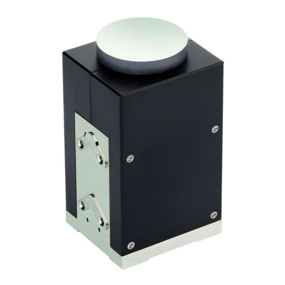
Page 12: Product View
3 Product Description Product View The S-335.2SHM1 and S-335.2SHM2 models have a mirror. Details on the mirrors can be found under "Mirrors" (p. 13) and under "Dimensions" (p. 45). Figure 1: Product view of an S-335 tip/tilt platform Base body... - Page 13 3 Product Description Figure 2: Alignment of the axes of the S-335 in relation to the cable exit Axis 1 (corresponds to channel 1 on the E-727.3SD/A controller) Axis 2 (corresponds to channel 2 on the E-727.3SD/A controller) Cable exit Figure 3: Maximum displacement in the positive direction of motion around axis 1.
-
Page 14: Product Labeling
Description S-335.2SH Product name 116010244 Serial number (example), individual for each S-335 Meaning of each position (from the left): 1 = internal information, 2 and 3 = year of manufacture, 4 to 9 = consecutive number Manufacturer's logo Country of origin:... -
Page 15: Scope Of Delivery
3 Product Description Labeling of the SubD 37 connector (m) Figure 5: Sub-D 37 connector (m) on the connecting cable of the S-335 Warning sign "Residual Voltage": Indicates risk of electric shock (p. 5) Scope of Delivery Item number Components... -
Page 16: Control
Piezo actuator 2 of the axis Platform The S-335 is a tip/tilt platform with differential piezo drive. Four piezo actuators are interconnected in pairs to realize tip/tilt motion on two axes. Both pairs of actuators are electrically switched so that when piezo voltage U... -
Page 17: Mirror
Most applications are not very sensitive to such deviations as long as the tip/tilt angle does not change. Each of the four piezo actuators of the S-335 is equipped with a strain gauge sensor. Therefore, in addition to the amplifier channel, a servo loop with a sensor channel must be available for each actuator pair. -
Page 18: Calculating Moments Of Inertia For Mirror And Mirror Holder
Axis through the center of gravity of the mirror Axis through the center of gravity of the mirror holder Mirror holder (example of a geometry) Axis through the pivot point of the platform of the S-335 ("rotational axis") Platform Version: 1.3.0 PZ276E S335 Tip/Tilt Platform... - Page 19 3 Product Description Figure 8: Example diagram: Platform with mirror holder and mirror; here with variables required for calculating the moments of inertia Distance from the axis through the center of gravity of the mirror to the rotational axis Distance from the axis through the center of gravity of the mirror holder to the rotational axis H/2 Half the mirror thickness Thickness of the mirror holder Distance from the rotational axis to the platform surface (see "Data Table"...
- Page 20 3 Product Description T = Distance from the rotational axis to the platform surface [mm], see "Data Table" (p. 41) Calculating the moment of inertia of the mirror Formula for calculating the moment of inertia of a rotationally symmetric mirror: Formula for calculating the moment of inertia of a rectangular mirror: with: = Moment of inertia of the mirror, in relation to the rotational axis [g•mm...
-
Page 21: Calculating The Resonant Frequency Of The Tip/Tilt Platform
= Resonant frequency of the S-335 with mirror [Hz] = Resonant frequency of the unloaded S-335 [Hz]; see "Data Table" (p. 41) = Moment of inertia of the platform of the S-335 [g•mm ], see "Data Table" (p. 41) = Moment of inertia of the mirror, in relation to the rotational axis, [g•mm... - Page 22 = Moment of inertia of the mirror holder, in relation to the rotational axis, [g•mm calculation see separate formula (p. 16) Further information on dynamic or static operation can be found in the PI catalog (CAT 130), in the section "Fundamentals of Piezo Technology". The catalog can be downloaded from our website http://www.pi.ws under Service >...
-
Page 23: Unpacking
Mechanical overload due to incorrect handling! Impermissible mechanical overload of the motion platform of the S-335 can cause damage to the piezo actuators, sensors, and flexures of the S-335 as well as loss of accuracy. Ship the S-335 in the original packaging only. -
Page 25: Installing
Touching the contacts in the connector can lead to an electric shock (max. 120 V DC) and minor injuries. Do not touch the contacts in the connector. Use the screws to secure the connector of the S-335 against being pulled out of the controller. NOTICE... - Page 26 NOTICE Damage when the mirror is removed! The following applies to models with mirror: The mirror of the S-335 may only be replaced by PI. Otherwise, the S-335 can be damaged. Do not remove the mirror of the S-335.
-
Page 27: Mounting The Mirror On The S-335.2Sh
− In the case of applications with large temperature changes: Make sure that the mirror and, if necessary, the mirror holder have the same or similar thermal expansion properties as the motion platform of the S-335 (material of the platform: titanium). - Page 28 Suitable centering aid for aligning the mirror For examples, see figures below. Figure 11: Example: S-335 with template for applying the adhesive to the four points Figure 12: Example: S-335 with centering aid for aligning the mirror Version: 1.3.0 PZ276E S335 Tip/Tilt Platform...
-
Page 29: Mounting The S-335
If you use a template: Remove the template. 3. Affix the mirror to the motion platform: a) If you use a centering aid: Carefully align the centering aid on the S-335 and affix it appropriately. b) Align the mirror appropriately or use the centering aid and place it carefully onto the motion platform of the S-335. - Page 30 M2.5 holes in the bottom of the S-335 for mounting onto a surface Figure 14: M2.5 holes in the side of the S-335 for mounting onto a suitable area Requirements You have read and understood the General Notes on Installation (p. 21).
-
Page 31: Connecting The S-335 To The Protective Earth Conductor
5 Installing Tools and accessories For the dimensions of the S-335 and the position and depth of the M2.5 holes, see "Dimensions" (p. 45). You have provided a suitable mounting surface: Four through-holes for M2.5 screws are provided. - Page 32 1. If necessary, firmly attach a suitable cable lug to the protective earth conductor. 2. Use the M4 screw (together with the flat and lock washers) to attach the cable lug of the protective earth conductor to the threaded hole in the S-335 as shown in the profile view.
-
Page 33: Removing The Transport Safeguard
5 Installing Removing the Transport Safeguard The S-335 is delivered with a protective cover. Figure 16: S-335 with protective cover, identical for all models Plastic cover (POM) for protecting during transit Requirements You have mounted the S-335 (p. 27). - Page 34 5 Installing Connecting the S335 to the controller E727.3SD 1. Plug the connector of the S-335 into the corresponding socket of the controller (see user manual of the controller). 2. Use the integrated screws to secure the connection against accidental disconnection.
-
Page 35: Starting And Operating
If the protective earth conductor is not or not properly connected, dangerous touch voltages can occur on the S-335 in the event of a malfunction or failure of the system. If there are touch voltages, touching the S-335 can result in minor injuries from electric shock. -
Page 36: Operating The S-335
Set the dynamic servo control parameters if the application requires it (see controller manual). INFORMATION Sound and vibration (e.g., footfall, knocks) can be transmitted to the S-335 and can affect its performance with regard to position stability. Avoid sound and vibration while the S-335 is being operated. -
Page 37: Discharging The S-335
The electronics and the required PC software were installed. All connections to the electronics were made (refer to the user manual for the electronics). Operating the S335 Follow the instructions for starting and operating the S-335 in the manual for the electronics (p. 11) used. Discharging the S335... -
Page 39: Maintenance
NOTICE Damage when the mirror is removed! The following applies to models with mirror: The mirror of the S-335 may only be replaced by PI. Otherwise, the S-335 can be damaged. Do not remove the mirror of the S-335. -
Page 40: Preparing The S-335 For Transport
Optic brush Cleaning the S335 Clean the surfaces and the mirror of the S-335 with bellows and/or an optic brush without exerting force. Do not use compressed air for cleaning. Do not do any ultrasonic cleaning. -
Page 41: Troubleshooting
Flatness of at least 30 μm The thermal expansion properties are similar to those of the S-335 (e.g., surfaces made of steel) Adhesive has run into the middle Contact our customer service hole or between the motion department (p. -
Page 43: Customer Service Department
9 Customer Service Department Customer Service Department For inquiries and orders, contact your PI sales engineer or send us an email (service@pi.de). If you have questions concerning your system, provide the following information: Product and serial numbers of all products in the system −... -
Page 45: Technical Data
10 Technical Data Technical Data Subject to change. You can find the latest product specifications on the product web page at www.pi.ws (https://www.pi.ws). In this Chapter Specifications ..........................41 Dimensions ..........................45 Pin Assignment ..........................47 10.1 Specifications 10.1.1 Data Table... - Page 46 10 Technical Data Drive Properties Unit S335.2SH S335.2SHM1 S335.2SHM2 Tolerance Drive type PICMA PICMA PICMA ® ® ® Electrical capacitance in θX μF ±20 % Electrical capacitance in θY μF ±20 % Mechanical Properties Unit Tolerance S335.2SH S335.2SHM1 S335.2SHM2 Resonant frequency in θX, ±20 % unloaded Resonant frequency in θX,...
-
Page 47: Maximum Ratings
To calculate the resonant frequency of the system of S-335 and mirror, see "Dynamic Behavior" (p. 13). The heat that is generated by the piezo actuator during dynamic operation limits the value for maximum power consumption. -
Page 48: Ambient Conditions And Classifications
10 Technical Data 10.1.3 Ambient Conditions and Classifications Pay attention to the following ambient conditions and classifications for the S-335: Area of application For indoor use only Maximum altitude 2000 m Air pressure 1100 hPa to 0.1 hPa Relative humidity Highest relative humidity 80 % for temperatures up to 31 °C... -
Page 49: Dimensions
10 Technical Data 10.2 Dimensions 10.2.1 S335.2SH Dimensions in mm. Note that the decimal points are separated by a comma in the drawings. Figure 18: S-335.2SH S335 Tip/Tilt Platform PZ276E Version: 1.3.0... -
Page 50: S-335.2Shm1
10 Technical Data 10.2.2 S335.2SHM1 Dimensions in mm. Note that the decimal points are separated by a comma in the drawings. Figure 19: S-335.2SHM1 Version: 1.3.0 PZ276E S335 Tip/Tilt Platform... -
Page 51: S-335.2Shm2
10 Technical Data 10.2.3 S335.2SHM2 Dimensions in mm. Note that the decimal points are separated by a comma in the drawings. Figure 20: S-335.2SHM2 10.3 Pin Assignment Figure 21: Sub-D 37 (m) piezo and sensor connection Signal* Function Ground Reserved Reserved for ID chip S335 Tip/Tilt Platform... - Page 52 10 Technical Data Signal* Function Reserved Reserved for ID chip Ground Ground SGS CH2+ SGS signal axis 2 (positive) Ground CH1+ SGS SGS signal axis 1 (positive) Reserved Reserved Reserved Reserved Piezo CH1+ Piezo voltage, axis 1 (positive) Piezo CH2+ Piezo voltage, axis 2 (positive) Piezo CH3+ 100 V fixed voltage...
-
Page 53: Old Equipment Disposal
Dispose of your old equipment according to international, national, and local rules and regulations. To fulfill the responsibility as the product manufacturer, Physik Instrumente (PI) GmbH & Co. KG undertakes environmentally correct disposal of all old PI equipment made available on the market after 13 August 2005 without charge. - Page 55 12 European Declarations of Conformity European Declarations of Conformity For the S-335, declarations of conformity were issued according to the following European statutory requirements: Low Voltage Directive EMC Directive RoHS Directive The standards applied for certifying conformity are listed below.
Need help?
Do you have a question about the S-335 and is the answer not in the manual?
Questions and answers