Table of Contents
Advertisement
Quick Links
MS207E
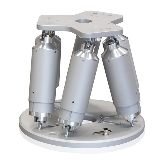
H-820 Hexapod Microrobot
User Manual
Version: 2.4.0
Physik Instrumente (PI) GmbH & Co. KG, Auf der Roemerstrasse 1, 76228 Karlsruhe, Germany
Phone +49 721 4846-0, Fax +49 721 4846-1019, Email info@pi.ws, www.pi.ws
Date: 12.01.2023
This document describes the following product:
H-820.D2
Hexapod microrobot, basic model, 20 kg load
capacity, 20 mm/s velocity, D-sub connector
Advertisement
Table of Contents

Related Manuals for PI H-820


Summary of Contents for PI H-820
- Page 1 H-820.D2 Hexapod microrobot, basic model, 20 kg load capacity, 20 mm/s velocity, D-sub connector Physik Instrumente (PI) GmbH & Co. KG, Auf der Roemerstrasse 1, 76228 Karlsruhe, Germany Phone +49 721 4846-0, Fax +49 721 4846-1019, Email info@pi.ws, www.pi.ws...
- Page 2 BiSS is a registered trademark of iC-Haus GmbH. © 2023 Physik Instrumente (PI) GmbH & Co. KG, Karlsruhe, Germany. The text, photographs, and drawings in this manual are protected by copyright. With regard thereto, Physik Instrumente (PI) GmbH & Co. KG retains all the rights.
-
Page 3: Table Of Contents
Contents About this Document Objective and Target Group of this User Manual ............1 Symbols and Typographic Conventions..............1 Figures ........................2 Other Applicable Documents ..................2 Downloading Manuals ....................3 Safety Intended Use ......................5 General Safety Instructions ..................5 Organizational Measures .................... - Page 4 Startup General Notes on Startup ..................27 Starting Up the Hexapod System ................28 Maintenance Performing a Maintenance Run ................29 Cleaning the Hexapod ....................30 Packing the Hexapod for Transport ................30 Troubleshooting Customer Service Department Technical Data 10.1 Specifications ......................41 10.1.1 Data Table ....................
-
Page 5: About This Document
Downloading Manuals ........................3 Objective and Target Group of this User Manual This user manual contains the information necessary for using the H-820 as intended. We assume that the user has basic knowledge of closed-loop systems, motion control concepts, and applicable safety measures. -
Page 6: Figures
For better understandability, the colors, proportions, and degree of detail in illustrations can deviate from the actual circumstances. Photographic illustrations may also differ and must not be seen as guaranteed properties. Other Applicable Documents The devices and software tools from PI mentioned in this documentation are described in separate manuals. Device/program Document Document content C-887.5xx controller... -
Page 7: Downloading Manuals
Contact our customer service department (p. 39). Downloading manuals 1. Open the website www.pi.ws. 2. Search the website for the product number (e.g., H-820). 3. Click the corresponding product to open the product detail page. 4. Click the Downloads tab. -
Page 9: Safety
The H-820 is built according to state-of-the-art technology and recognized safety standards. Improper use of the H-820 may result in personal injury and/or damage to the H-820. Use the H-820 for its intended purpose only, and only when it is in perfect condition. Read the user manual. - Page 10 2 Safety If you give the H-820 to other users, include this user manual as well as all other relevant information provided by the manufacturer. Do the work only if the user manual is complete. Missing information due to an incomplete user manual can result in minor injury and damage to equipment.
-
Page 11: Product Description
Suitable Controllers ........................15 Features and Applications The H-820 hexapod achieves a velocity of up to 20 mm/s. It can be loaded with a maximum of 20 kg in a vertical orientation and with a maximum of 10 kg in any other orientation. -
Page 12: Product View
(three translational axes and three rotational axes). Each strut is equipped with the following components: One actuator Reference and limit switches Joints for connecting to the base plate and motion platform Version: 2.4.0 MS207E H-820 Hexapod Microrobot... -
Page 13: Reference Switch And Limit Switches
3.3.3 Control Der hexapod is intended for operation with a suitable controller from PI (p. 15). The controller makes it possible to command motion of individual axes, combinations of axes or all six axes at the same time in a single motion command. - Page 14 A given rotation in space is calculated from the individual rotations in the order U -> V- > W. For further information on the center of rotation, see the glossary (p. 51). Version: 2.4.0 MS207E H-820 Hexapod Microrobot...
- Page 15 The rotation around the U axis tilts the rotational axes V and W. Figure 3: Rotation around the U axis Platform in reference position Platform position: U = 10 (U parallel to spatially-fixed X axis) H-820 Hexapod Microrobot MS207E Version: 2.4.0...
- Page 16 The rotation around the V axis tilts the rotational axes U and W. Figure 4: Rotation around the V axis Platform in reference position Platform position: U = 10, V = –10 (U and V parallel to the platform level) Version: 2.4.0 MS207E H-820 Hexapod Microrobot...
-
Page 17: Id Chip
(e.g., geometry data and control parameters). The configuration data for customized hexapods is only stored on the controller if the hexapod and controller are delivered together, or if PI was correspondingly informed before delivery of the controller. -
Page 18: Scope Of Delivery
2 flat washers, form A-4.3 DIN 7090 2 safety washers, Schnorr Ø 4 mm N0110 Note that the cables required for connecting the H-820 to the electronics must be ordered separately. Optional Accessories Order number Data transmission cable, available lengths Data transmission cable for hexapods, drag chain compatible, HD D-sub 78 C-815.82D02... -
Page 19: Suitable Controllers
EtherCAT interface, motion stop C-887.533 6-axis controller for hexapods, TCP/IP, RS-232, benchtop device, incl. control of two additional axes, EtherCAT interface, motion stop, analog inputs To order, contact our customer service department (p. 39). H-820 Hexapod Microrobot MS207E Version: 2.4.0... -
Page 21: Unpacking
7. Compare the contents with the items listed in the contract and the packing list. If any of the parts are wrong or are missing, contact PI immediately. 8. Inspect the hexapod for signs of damage. If there is any sign of damage, contact PI immediately. -
Page 23: Installing
The use of the software is recommended when the hexapod is located in a limited installation space and/or operated with a spatially limiting load. For details on activation and configuration of PIVeriMove, see the C887T0002 technical note (in the scope of delivery of the software). H-820 Hexapod Microrobot MS207E Version: 2.4.0... -
Page 24: Determining The Permissible Load And Workspace
5 Installing Determining the Permissible Load and Workspace Tools and Accessories PC with Windows operating system with the PI Hexapod Simulation Tool installed. For further information, see the A000T0068 technical note. Determining the workspace and the permissible load of the hexapod ... -
Page 25: Mounting The Hexapod On A Surface
Figure 6: Mounting holes in the base plate Requirements You have read and understood the General Notes on Installation (p. 19). Tools and accessories Hex key 5.0 and three of the supplied screws (p. 14). H-820 Hexapod Microrobot MS207E Version: 2.4.0... -
Page 26: Fixing The Load To The Hexapod
(p. 46) together with the load to be mounted. Only use screws that do not project under the motion platform after being screwed in. Only mount the hexapod and the load on the mounting fixtures (holes) intended for this purpose. Version: 2.4.0 MS207E H-820 Hexapod Microrobot... - Page 27 The arrangement of the mounting holes in the motion platform of the hexapod can be found in the dimensional drawing (p. 46) as well as in the corresponding figure. 2. Use the screws to fix the load to the selected mounting holes in the motion platform. H-820 Hexapod Microrobot MS207E Version: 2.4.0...
-
Page 28: Optional: Removing The Coordinate Cube
Connect the hexapod and the controller to each other: − Pay attention to the assignment specified on the labeling of the sockets, plug connectors, and cables. Pay attention to the mechanical coding of connectors and sockets. − − Do not use force. Version: 2.4.0 MS207E H-820 Hexapod Microrobot... - Page 29 Controller Refer to "Suitable Controllers" (p. 15) Hexapod H-820.D2 Power adapter, from the scope of delivery of the controller, 24 V DC output Data transmission cable* Power supply cable* * Must be ordered separately. H-820 Hexapod Microrobot MS207E Version: 2.4.0...
-
Page 31: Startup
Do not place any objects in areas where they can be caught by moving parts. Stop the motion immediately if a controller malfunction occurs. H-820 Hexapod Microrobot MS207E Version: 2.4.0... -
Page 32: Starting Up The Hexapod System
Starting up the hexapod system 1. Start up the controller (refer to the user manual of the controller). 2. Run a few motion cycles for test purposes (refer to the user manual of the controller). Version: 2.4.0 MS207E H-820 Hexapod Microrobot... -
Page 33: Maintenance
Cleaning the Hexapod ........................30 Packing the Hexapod for Transport ..................... 30 PI offers a range of wraparound services for all their products, many of which are designed to increase the system’s lifetime and uptime: Remote system setup: An expert ensures that your system is optimized and runs ... -
Page 34: Cleaning The Hexapod
1. Command motion of the hexapod to the transport position: X = Y = Z = U = V = W = 0 2. Uninstall the hexapod system: a) Remove the load from the motion platform of the hexapod. Version: 2.4.0 MS207E H-820 Hexapod Microrobot... - Page 35 10. Put the cover onto the outer box, see figure. 11. Secure the outer box on the pallet with two parallel strapping bands. 12. Wrap the box and pallet with stretch film. Step 4 a Step 4 b H-820 Hexapod Microrobot MS207E Version: 2.4.0...
- Page 36 7 Maintenance Step 4 d Right: Appropriate orientation of the foam insert, view from above Step 6 Right: Appropriate orientation of the foam cover, view from above Step 7 Step 9 Step 10 Version: 2.4.0 MS207E H-820 Hexapod Microrobot...
- Page 37 7 Maintenance Step 12 The upper box contains the controller. H-820 Hexapod Microrobot MS207E Version: 2.4.0...
-
Page 39: Troubleshooting
Faulty motor occurs with maximum or minimum Sensor defective displacement of the platform in Z. Blocked or broken Contact our customer service department joint (p. 39). H-820 Hexapod Microrobot MS207E Version: 2.4.0... - Page 40 If you do not use the "Motion Stop" functionality: Make sure that the C887B0038 shorting plug from the scope of delivery of the controller is inserted in the E-Stop socket. If you use the "Motion Stop" functionality: Version: 2.4.0 MS207E H-820 Hexapod Microrobot...
- Page 41 2. Activate the 24 V Out 7 A output with "Make contact" (for details, refer to the user manual for the controller). If you use the C-887.MSB motion-stop-box from PI: Press the mushroom button first to unlock it, then press the green pushbutton.
- Page 42 "Hexapod does not move" section not possible. reference move. applies to your problem. If the problem with your hexapod is not listed in the table or cannot be solved as described, contact our customer service department (p. 39). Version: 2.4.0 MS207E H-820 Hexapod Microrobot...
-
Page 43: Customer Service Department
9 Customer Service Department Customer Service Department For inquiries and orders, contact your PI sales engineer or send us an email (mailto:service@pi.de). If you have questions concerning your system, provide the following information: − Product and serial numbers of all products in the system Firmware version of the controller (if applicable) −... -
Page 45: Technical Data
200 mrad/s Maximum angular velocity in θZ 200 mrad/s Typical velocity in X 2 mm/s Typical velocity in Y 2 mm/s Typical velocity in Z 2 mm/s Typical angular velocity in θX 20 mrad/s H-820 Hexapod Microrobot MS207E Version: 2.4.0... - Page 46 Brushless DC motor Nominal voltage 24 V Mechanical properties H-820.D2 Tolerance Maximum holding force, base plate in any orientation 5 N Maximum holding force, base plate horizontal 200 N Overall mass 15 kg Material Aluminum Version: 2.4.0 MS207E H-820 Hexapod Microrobot...
-
Page 47: Maximum Ratings
Specifications for Data Transmission and Power Supply Cables The following table lists the technical data of all optionally available cable sets, irrespective of whether they are suitable for the H-820 hexapods. Refer to "Optional Accessories" (p. 14)for a selection of suitable cable sets. - Page 48 Maximum number of bending cycles 1 million Operating temperature range -10 to +70 °C Power supply cable, straight connectors Unit Minimum bending radius in a drag chain Minimum bending radius with the fixed installation Outer diameter Version: 2.4.0 MS207E H-820 Hexapod Microrobot...
-
Page 49: Ambient Conditions And Classifications
Highest relative humidity of 80% at temperatures of up to 31°C, decreasing linearly to a relative humidity of 50% at 40°C Degree of protection according IP20 to IEC 60529 Area of application For indoor use only Maximum altitude 2000 m H-820 Hexapod Microrobot MS207E Version: 2.4.0... -
Page 50: Dimensions
Dimensions in mm. Note that the decimal points are separated by a comma in the drawings. Figure 10: H-820.D2 Hexapod, at zero position of nominal travel range If the controller's factory settings are used for the coordinate system and the center of rotation, the hexapod in the figure corresponds to the position X=Y=Z=U=V=W=0. -
Page 51: Data Transmission Connection
CH3 LimN OUT CH3 A+ OUT CH3 B+ OUT CH3 A- OUT CH3 B- OUT CH4 Sign IN CH4 MAGN IN CH4 Ref OUT CH4 LimP OUT CH4 LimN OUT CH4 A+ OUT CH4 B+ OUT H-820 Hexapod Microrobot MS207E Version: 2.4.0... - Page 52 CH6 MAGN IN CH6 Ref OUT CH6 LimP OUT CH6 LimN OUT CH6 A+ OUT CH6 B+ OUT CH6 A- OUT CH6 B- OUT ID Chip Brake/Enable drive 24 V input Power Good 24 V output Version: 2.4.0 MS207E H-820 Hexapod Microrobot...
-
Page 53: Old Equipment Disposal
Dispose of your old equipment according to international, national, and local rules and regulations. To fulfill the responsibility as the product manufacturer, Physik Instrumente (PI) GmbH & Co. KG undertakes environmentally correct disposal of all old PI equipment made available on the market after 13 August 2005 without charge. -
Page 55: Glossary
The X, Y and Z axes are also referred to as translational axes. The intersection of the axes X, Y, and Z of the spatially fixed Cartesian coordinate system (0,0,0) is referred to as the origin. H-820 Hexapod Microrobot MS207E Version: 2.4.0... - Page 56 The Z axis is perpendicular to the base plate of the hexapod. The following example figures of the H-810 hexapod show that the coordinate system does not move along with motion of the platform. Figure 11: H-810 hexapod in the reference position. Cable exit Version: 2.4.0 MS207E H-820 Hexapod Microrobot...
- Page 57 12 Glossary Figure 12: H-810 hexapod, the platform of which has been moved in X. Cable exit H-820 Hexapod Microrobot MS207E Version: 2.4.0...
-
Page 59: Appendix
The following test cycles are performed: Motion over the entire travel range with at least 20 measuring points, in at least five cycles. Motion over partial sections, e.g., ±1 mm in increments of for example, 100 µm H-820 Hexapod Microrobot MS207E Version: 2.4.0... -
Page 61: European Declarations Of Conformity
13 Appendix 13.2 European Declarations of Conformity For the H-820, declarations of conformity were issued according to the following European statutory requirements: EMC Directive RoHS Directive The standards applied for certifying conformity are listed below. EMC: EN 61326-1 Safety: EN 61010-1...
Need help?
Do you have a question about the H-820 and is the answer not in the manual?
Questions and answers