Table of Contents
Advertisement
Quick Links
MP47E
M-06x Rotation Stage
User Manual
Version: 2.1
Date: 31.08.2020
This document describes the following
precision rotation stages (>360°):
M-06x.DG:
with closed-loop DC gear motor
M-06x.PD:
with DC motor and PWM control
x stands for the platform diameter:
0 = 60 mm
1 = 100 mm
2 = 120 mm
Physik Instrumente (PI) GmbH & Co. KG, Auf der Roemerstr. 1, 76228 Karlsruhe, Germany
Phone: +49 721 4846-0, Fax: +49 721 4846-1019, E-mail: info@pi.ws
Advertisement
Table of Contents

Related Manuals for PI M-06 Series


Summary of Contents for PI M-06 Series
- Page 1 0 = 60 mm 1 = 100 mm 2 = 120 mm Physik Instrumente (PI) GmbH & Co. KG, Auf der Roemerstr. 1, 76228 Karlsruhe, Germany Phone: +49 721 4846-0, Fax: +49 721 4846-1019, E-mail: info@pi.ws...
- Page 2 With regard thereto, Physik Instrumente (PI) GmbH & Co. KG retains all the rights. The use of any text, images and drawings is permitted only in part and only when indicating the source.
-
Page 3: Table Of Contents
Contents About this Document Objective and Target Audience of this User Manual ..........3 Symbols and Typographic Conventions ............... 3 Definition ....................... 4 Figures ........................4 Other Applicable Documents ................5 Safety Intended Use ......................6 General Safety Instructions .................. 6 Organizational Measures .................. - Page 4 Maintenance General Notes on Maintenance ................32 Performing a Maintenance Run ................32 Cleaning the M-06x ....................33 Troubleshooting Customer Service Technical Data 10.1 Specifications......................39 10.1.1 Data Table ..................39 10.1.2 Maximum Ratings ................40 10.1.3 Ambient Conditions and Classifications ...........41 10.1.4 Reference Point Switch Specifications ..........41 10.2 Dimensions ......................42 10.3...
-
Page 5: About This Document
1 About this Document About this Document In this Chapter Objective and Target Audience of this User Manual ............. 3 Symbols and Typographic Conventions ................ 3 Definition ........................4 Figures ........................... 4 Other Applicable Documents ..................6 Downloading Manuals ....................6 1.1 Objective and Target Audience of this User Manual This user manual contains the information needed for the intended use of the M-06x. -
Page 6: Definition
1 About this Document Symbol/Label Meaning Action consisting of several steps whose sequential order must be observed Action consisting of one or several steps whose sequential order is irrelevant List item p. 5 Cross-reference to page 5 RS-232 Labeling of an operating element on the product (example: socket of the RS-232 interface) Warning sign on the product which refers to detailed... -
Page 7: Other Applicable Documents
1 About this Document 1.5 Other Applicable Documents The devices and software tools which are mentioned in this documentation are described in their own manuals. Product Document Stages with electric motors MP119EK Short Instructions Matching controller User manual for the applied controller M-06x Rotation Stage MP47E Version: 2.1... -
Page 8: Safety
2 Safety Safety In this Chapter Intended Use ......................... 6 General Safety Instructions ................... 6 Organizational Measures ....................7 2.1 Intended Use The M-06x is a laboratory device as defined by DIN EN 61010. It is intended for indoor use and use in an environment that is free of dirt, oil and lubricants. In accordance with its design and realization, the M-06x is intended for single-axis positioning, adjusting and shifting of loads at different velocities. -
Page 9: Organizational Measures
2 Safety 2.3 Organizational Measures User manual Always keep this user manual available with the M-06x. The latest versions of the user manuals are available for download (p. 6) on our website. Add all information given by the manufacturer to the user manual, for example supplements or technical notes. -
Page 11: Product Description
3 Product Description Product Description In this Chapter Model Overview ......................9 Product View ....................... 11 Product Labeling ......................12 Direction of Motion ....................... 13 Scope of Delivery ......................14 Accessories ......................... 14 Suitable Controllers ..................... 14 Technical Features ...................... 14 3.1 Model Overview Classification of the stages The stages of the M-060, M-061 and M-062 series are summarized in this manual... - Page 12 3 Product Description Detailed model overview Order Product name number M-060.DG Precision Rotation Stage, Ø 60 mm, 360°, closed-loop DC Gear Motor M-060.PD Precision Rotation Stage, Ø 60 mm, 360°, ActiveDrive DC Motor M-061.DG Precision Rotation Stage, Ø 100 mm, 360°, closed-loop DC Gear Motor M-061.PD Precision Rotation Stage, Ø...
-
Page 13: Product View
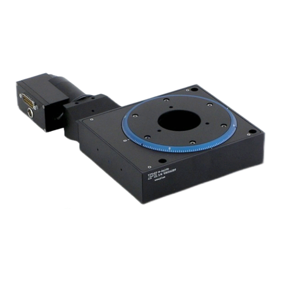
3 Product Description 3.2 Product View Figure 1: Components of the M-06x.PD models Figure 2: Components of the M-06x.DG models Motor Motor flange Platform Scale ring Base body Controller connection (Sub-D 15 panel plug) Power supply connection (Mini XLR3 panel plug) M-06x Rotation Stage MP47E Version: 2.1... -
Page 14: Product Labeling
Serial number (example), individual for each M-06x Meaning of the places (counting from left): 1 = internal information, 2 and 3 = manufacturing year, 4 to 9 = consecutive numbers WWW.PI.WS Manufacturer's address (website) Version: 2.1 MP47E M-06x Rotation Stage... -
Page 15: Direction Of Motion
3 Product Description Position Labeling Description Old equipment disposal (p. 47) Country of origin: Germany Country of origin 0° mark in the base body Graduation on the scale ring of the moving platform (detail) Short line: 2° Medium line: 10° ... -
Page 16: Scope Of Delivery
3 Product Description 3.5 Scope of Delivery Item Component number M-06x.xx Rotation stage according to the order (p. 9) MP119EK Short instructions for stages with electric motors Only M-060.xx models: 2493 Screw set for mounting the rotation stage: 6 M4x12 socket head cap screws ISO 4762 ... -
Page 17: Integrated Pwm Amplifier
3 Product Description After a reference move of the M-06x, the 0° mark on the scale ring of the moving platform is above the 0° mark in the base body. 3.6.3 Integrated PWM Amplifier The M-06x.PD models with direct drive are equipped with a PWM amplifier ("ActiveDrive concept"). -
Page 19: Unpacking
3. Inspect the contents for signs of damage. If parts are missing or you notice signs of damage, contact PI immediately. 4. Keep all packaging materials in case the product needs to be returned. M-06x Rotation Stage MP47E Version: 2.1... -
Page 21: Installation
5 Installation Installation In this Chapter General Notes on Installation ..................19 Optional: Modifying the Connection Orientation on the M-06x........20 Optional: Aligning the Hole Pattern of the Platform ............. 22 Mounting the M-06x on a Surface ................24 Affixing the Load to the M-06x ..................26 Connecting the Motor Cable to the M-06x .............. -
Page 22: Optional: Modifying The Connection Orientation On The M-06X
5 Installation NOTICE Heating up of the M-06x during operation! The heat produced during operation of the M-06x can affect your application. Install the M-06x so that your application is not affected by the dissipating heat. INFORMATION For optimum repeatability, all components must be firmly affixed to each other. ... - Page 23 5 Installation Figure 5: Optional: Continuous rotation of the motor around its axis Figure 6: Position of the grub screws on the motor flange (left: top side, right: bottom side) Grub screw Motor flange Motor case M-06x Rotation Stage MP47E Version: 2.1...
-
Page 24: Optional: Aligning The Hole Pattern Of The Platform
5 Installation Prerequisites The rotation stage is not mounted on a surface. The rotation stage is not connected to the controller and the power supply. Tools and accessories Allen wrench AF 2 Changing the orientation for connection 1. - Page 25 5 Installation The scale ring is fixed on the moving platform of the M-06x with three grub screws. Figure 7: Position of the grub screws on the scale ring Access to the grub screw Mounting hole for load Scale ring 0°...
-
Page 26: Mounting The M-06X On A Surface
5 Installation 3. Tighten the grub screws on the scale ring. 4. Check that the scale ring is affixed firmly. 5.4 Mounting the M-06x on a Surface NOTICE Warping of the M-06x due to mounting on uneven surfaces! Mounting the M-06x on an uneven surface can warp the M-06x. Warping reduces the accuracy. - Page 27 5 Installation Prerequisites You have read and understood the general notes on installation (p. 19). You have provided a suitable surface (for the required position and depth of the holes for accommodating the screws, see "Dimensions" (p. 42)): −...
-
Page 28: Affixing The Load To The M-06X
5 Installation 5.5 Affixing the Load to the M-06x NOTICE Impermissibly high load on the rotation stage! An impermissibly high load interferes with the motion of the moving platform and can damage the rotation stage. In respect to the mass and mounting type of the load, observe the maximum permissible forces that are allowed to act on the moving platform according to the specification (p. -
Page 29: Connecting The Motor Cable To The M-06X
The motor cable is not connected to the controller. Tools and accessories Suitable motor cable from PI Connecting the motor cable to the M-06x 1. Connect the rotation stage to the controller using the motor cable. 2. Secure the connectors with the integrated screws against being unintentionally pulled out of the rotation stage. -
Page 30: Connecting The Power Supply To The M-06X
5 Installation 5.7 Connecting the Power Supply to the M-06x Connecting a power supply is only necessary for the M-06x.PD models. Prerequisites The power cord is not connected to the power socket. Tools and accessories Supplied components: − 24 V wide-range-input power supply −... -
Page 31: Start-Up
6 Start-Up Start-Up In this Chapter General Notes on Start-Up ..................29 Starting Up the rotation stage ..................31 6.1 General Notes on Start-Up NOTICE Damage from collisions! Collisions can damage the rotation stage, the load to be moved and the environment. ... - Page 32 INFORMATION The repeatability of the positioning is only ensured when the reference point switch is always approached from the same side. Controllers from PI fulfill this requirement due to the automatic direction sensing for reference moves to the reference point switch.
-
Page 33: Starting Up The Rotation Stage
(see user manual of the controller and of the PC software): − If you use a controller from PI: Select the entry in the stage database that exactly fits the stage model used. 3. Start a few motion cycles for testing purposes (see user manual of the controller). -
Page 34: Maintenance
7 Maintenance Maintenance In this Chapter General Notes on Maintenance ................... 32 Performing a Maintenance Run ................... 32 Cleaning the M-06x ..................... 33 7.1 General Notes on Maintenance NOTICE Damage due to improper maintenance! Improper maintenance can lead to misalignment and failure of the M-06x. ... -
Page 35: Cleaning The M-06X
7 Maintenance Lubrication Under laboratory conditions, the rotation stage only needs extra lubrication in exceptional cases. For continuous industrial use, the lubrication intervals must be defined individually. Do not lubricate the M-06x without consulting our customer service department (p. 37). ... -
Page 37: Troubleshooting
If present: Check the power supply of the heard. stage. When a controller from PI is Motion error = The difference between the used: There is a motion error current position and the commanded position of the axis. -
Page 39: Customer Service
9 Customer Service Customer Service For inquiries and orders, contact your PI sales engineer or send us an e-mail (mailto:service@pi.de). If you have questions concerning your system, have the following information ready: − Product codes and serial numbers of all products in the system −... -
Page 41: Technical Data
10 Technical Data 10 Technical Data In this Chapter Specifications ......................39 Dimensions ........................42 Pin Assignment ......................44 10.1 Specifications 10.1.1 Data Table M-060.PD / M-061.PD / M-060.DG / M-061.DG / Unit Tolerance M-062.PD M-062.DG Motion and positioning Rotation range >360 >360 °... -
Page 42: Maximum Ratings
10 Technical Data M-060.PD / M-061.PD / M-060.DG / M-061.DG / Unit Tolerance M-062.PD M-062.DG Drive properties Motor type DC motor, ActiveDrive DC gear motor Operating voltage 0 to ±12 Motor power Reference switch Hall effect Hall effect Miscellaneous Operating temperature range -10 to 40 -10 to 40 °C... -
Page 43: Ambient Conditions And Classifications
10 Technical Data 10.1.3 Ambient Conditions and Classifications The following ambient conditions and classifications must be observed for the M-06x: Area of application For indoor use only Maximum altitude 2000 m Relative humidity Max. 80 % for temperatures up to 31 °C Linearly decreasing to 50 % at 40 °C Storage temperature -10 °C to 40 °C... -
Page 44: Dimensions
10 Technical Data 10.2 Dimensions Dimensions in mm. Note that the decimal places are separated by a comma in the drawings Version: 2.1 MP47E M-06x Rotation Stage... - Page 45 10 Technical Data Series M-060 M-061 M-062 Model 12.5 12.5 21.5 21.5 80.8 83.8 80.8 83.8 80.8 83.8 59.3 51.3 59.3 51.3 59.3 51.3 M-06x Rotation Stage MP47E Version: 2.1...
-
Page 46: Pin Assignment
10 Technical Data 10.3 Pin Assignment 10.3.1 Sub-D 15 (m) Controller Connection Figure 10: Sub-D 15 (m) controller connection, front view M-06x.DG models Signal Direction Not connected Motor (-) Input Motor (+) Input Not connected Not connected + 5 V (encoder) Input Not connected Not connected... -
Page 47: Mini Xlr3 (M) Power Supply Connection
10 Technical Data M-06x.PD models Signal Direction Not connected Not connected Not connected MAGN (PWM magnitude) Input SIGN (PWM sign) Input + 5 V Input Not connected Not connected Reference Output Encoder A (+) Output Encoder A (-) Output Encoder B (+) Output Encoder B (-) Output... -
Page 49: Old Equipment Disposal
GmbH & Co. KG undertakes environmentally correct disposal of all old PI equipment made available on the market after 13 August 2005 without charge. Any old PI equipment can be sent free of charge to the following address: Physik Instrumente (PI) GmbH & Co. KG Auf der Roemerstr. - Page 51 12 EC Declaration of Conformity 12 EC Declaration of Conformity For the M-06x, an EC Declaration of Conformity has been issued in accordance with the following European directives: • 2004/108/EC, EMC Directive • 2011/65/EU, RoHS Directive The applied standards certifying the conformity are listed below. •...
Need help?
Do you have a question about the M-06 Series and is the answer not in the manual?
Questions and answers