Table of Contents
Advertisement
Quick Links
MP136E
U651 Rotation Stage
User Manual
Version: 1.3.0
Physik Instrumente (PI) GmbH & Co. KG, Auf der Roemerstrasse 1, 76228 Karlsruhe, Germany
Phone +49 721 4846-0, Fax +49 721 4846-1019, Email info@pi.ws, www.pi.ws
Date: 02.12.2020
This document describes the following products:
U651.03
Rotation stage with low profile and PILine®
ultrasonic piezo motors, >360° rotation range,
velocity 540 °/s, incremental encoder,
resolution 9 µrad, D-sub connector
U651.03V
Rotation stage with low profile and PILine®
ultrasonic piezo motors, >360° rotation range,
velocity 540 °/s, incremental encoder,
resolution 9 µrad, D-sub connector, vacuum
compatible to 10
hPa
-6
U651.04
Rotation stage with low profile and PILine®
ultrasonic piezo motors, >360° rotation range,
velocity 540 °/s, incremental encoder,
resolution 4 µrad, D-sub connector
U651.04V
Rotation stage with low profile and PILine®
ultrasonic piezo motors, >360° rotation range,
velocity 540 °/s, incremental encoder,
resolution 4 µrad, D-sub connector, vacuum
compatible to 10
hPa
-6
Advertisement
Table of Contents

Related Manuals for PI U-651 Series


Summary of Contents for PI U-651 Series
- Page 1 >360° rotation range, velocity 540 °/s, incremental encoder, resolution 4 µrad, D-sub connector, vacuum compatible to 10 Physik Instrumente (PI) GmbH & Co. KG, Auf der Roemerstrasse 1, 76228 Karlsruhe, Germany Phone +49 721 4846-0, Fax +49 721 4846-1019, Email info@pi.ws, www.pi.ws...
- Page 2 The patents held by PI are found in our patent list: https://www.physikinstrumente.com/en/about-pi/patents © 2020 Physik Instrumente (PI) GmbH & Co. KG, Karlsruhe, Germany. The text, photographs and drawings in this manual are protected by copyright. With regard thereto, Physik Instrumente (PI) GmbH & Co. KG retains all the rights.
-
Page 3: Table Of Contents
Contents About this Document Objective and Target Audience of this User Manual..........1 Symbols and Typographic Conventions..............1 Definition of Terms ..................... 2 Figures ........................2 Other Applicable Documents ..................3 Downloading Manuals ....................3 Safety Intended Use ......................5 General Safety Instructions .................. - Page 4 Maintenance General Notes on Maintenance ................29 Doing a Maintenance Run ..................29 Cleaning the U-651 ....................30 Troubleshooting Customer Service Technical Data 10.1 Specifications ......................35 10.1.1 Data Table ....................35 10.1.2 Reference Switch Specifications ..............36 10.1.3 Maximum Ratings ..................36 10.1.4 Specifications for Vacuum-Compatible Versions ........
-
Page 5: About This Document
1 About this Document About this Document In this Chapter Objective and Target Audience of this User Manual ..............1 Symbols and Typographic Conventions ..................1 Definition of Terms ........................2 Figures ............................2 Other Applicable Documents ......................3 Downloading Manuals ........................3 Objective and Target Audience of this User Manual This user manual contains the information required for using the U-651 as intended. -
Page 6: Definition Of Terms
1 About this Document Symbol/Label Meaning Action consisting of several steps with strict sequential order Action consisting of one or more steps without relevant sequential order. Bullet p. 5 Cross-reference to page 5 RS232 Label on the product indicating an operating element (example: RS-232 interface socket) Warning signs attached to the product that refer to detailed information in this manual. -
Page 7: Other Applicable Documents
1 About this Document Other Applicable Documents The devices and software tools from PI mentioned in this documentation are described in separate manuals. Description Document C-867.1U PILine® Controller MS223E User Manual C-867.2U2 PILine® Controller MS231E User Manual C-867.10C885 PILine® Controller Module... -
Page 9: Safety
2 Safety Safety In this Chapter Intended Use ..........................5 General Safety Instructions......................5 Organizational Measures ....................... 6 Intended Use The U-651 is a laboratory device as defined by DIN EN 61010-1. It is intended for indoor use and use in an environment that is free of dirt, oil and lubricants. In accordance with its design and realization, the U-651 is intended for single-axis positioning, adjusting and rotation of loads in at different velocities in interval operation. -
Page 10: Organizational Measures
2 Safety If a protective earth conductor is not or not properly connected, dangerous touch voltages can occur on the U-651 in the case of malfunction or failure of the system. If there are touch voltages, touching the U-651 can result in minor injuries from electric shock. ... -
Page 11: Product Description
3 Product Description Product Description In this Chapter Model Overview ..........................7 Product View ..........................8 Product Labeling ..........................8 Scope of Delivery ......................... 10 Suitable Controllers ........................10 Accessories ........................... 10 Technical Features ........................11 Model Overview The U-651 is available in the following versions: Model Description U-651.03... -
Page 12: Product View
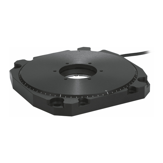
3 Product Description Product View Figure 1: U-651 product view 0° mark* in the base body Platform Base body 0° mark* of the platform Cable exit The arrow in the figure shows the positive direction of motion. *0° mark: The 0° mark of the platform is at the 0° mark in the base body after the U-651 does a reference move. - Page 13 Meaning of each position (from the left): 1 = internal information 2 and 3 = year of manufacture 4 to 9 = consecutive number WWW.PI.WS Manufacturer's address (website) Data matrix code (example; contains the serial number) Old equipment disposal (p. 45)
-
Page 14: Scope Of Delivery
3 Product Description Scope of Delivery Product number Description U-651 Rotation stage according to order (p. 7) 000036450 M4 screw set for protective earth, consisting of: 1 flat-head screw with cross recess, M4x8, ISO 7045 2 lock washers 2 flat washers ... -
Page 15: Technical Features
ID chip. When switched on or rebooted, controllers from PI read the data from the ID chip. You will find further information on ID chip recognition in the manual for the controller. -
Page 17: Unpacking
When handling the vacuum version of the rotation stage, attention must be paid to appropriate cleanliness. At PI, all parts are cleaned before assembly. Powder-free gloves are worn during assembly and measuring. In addition, the rotation stage is wipe cleaned afterwards and then shrink-wrapped twice in vacuum-compatible film. -
Page 19: Installation
5 Installation Installation In this Chapter General Notes on Installing ......................15 Connecting the U-651 to the Protective Earth Conductor ............17 Mounting the U-651 onto a Surface .................... 18 Fixing the Load to the U-651 ......................20 Connecting the Vacuum Version to the Controller ..............22 General Notes on Installing CAUTION Dangerous voltage and residual charge on piezo actuators! - Page 20 Unsuitable cables can cause damage to the controller and affect the performance of the U-651. Only use genuine PI parts to connect the U-651 to the controller. If you need longer cables, use extension cables from PI (p. 10).
-
Page 21: Connecting The U-651 To The Protective Earth Conductor
5 Installation Connecting the U651 to the Protective Earth Conductor INFORMATION Pay attention to the applicable standards for connecting the protective earth conductor. On the U-651, there is an M4 hole next to the cable exit for connecting the protective earth conductor. -
Page 22: Mounting The U-651 Onto A Surface
5 Installation Tools and accessories Suitable protective earth conductor: Cross-sectional area of the cable ≥0.75 mm M4 screw set supplied for connecting the protective earth conductor (p. 10) Suitable screwdriver Connecting the U651 to the protective earth conductor 1. - Page 23 5 Installation Figure 6: U-651: Holes in the base body for M6 screws (white arrows) or M4 screws (black arrows) Requirements You have read and understood the general notes on installation (p. 15). You have provided a suitable underlying surface (see "Dimensions" (p. 42) for the required position of the holes for the screws).
-
Page 24: Fixing The Load To The U-651
5 Installation Mounting the U651 onto a surface 1. Align the U-651 on the underlying surface so that the holes selected in the U-651 (see arrows in the figure) are in line with the corresponding holes in the underlying surface. 2. - Page 25 5 Installation Figure 7: U-651, M3 holes for fixing the load Requirements You have read and understood the general notes on installation (p. 15). You have mounted the U-651 onto an underlying surface (p. 18) properly. The U-651 is not connected to the controller. ...
-
Page 26: Connecting The Vacuum Version To The Controller
5 Installation Connecting the Vacuum Version to the Controller It is necessary to install a vacuum feedthrough (p. 10) for the vacuum version of the U-651. Requirements You have read and understood the general notes on installation (p. 15). ... -
Page 27: Starting And Operating
6 Starting and Operating Starting and Operating In this Chapter General Notes on Starting ......................23 Starting and Operating the U-651 ....................26 Adjusting Parameter Values when Using Extension Cables ............27 General Notes on Starting CAUTION Risk of electric shock if the protective earth conductor is not connected! If a protective earth conductor is not or not properly connected, dangerous touch voltages can occur on the U-651 in the case of malfunction or failure of the system. - Page 28 Operating voltages that are too high or incorrectly connected can cause damage to the U-651. Operate the U-651 only with controllers/drivers and original accessories from PI. Do not exceed the operating voltage range (p. 36) for which the U-651 is specified.
- Page 29 6 Starting and Operating NOTICE Damage due to collisions! Collisions can damage the U-651, the load to be moved, and the surroundings. Make sure that no collisions are possible between the U-651, the load to be moved, and the surroundings in the motion range of the U-651. ...
-
Page 30: Starting And Operating The U-651
6 Starting and Operating INFORMATION To generate the maximum force, it is necessary to run in when starting the U-651 and after longer downtimes; refer also to "Influence of Downtimes on the Torque" (p. 41). The U-651 reaches its maximum torque after running in. ... -
Page 31: Adjusting Parameter Values When Using Extension Cables
6 Starting and Operating Starting the U651 Start the axis (refer to the controller manual). Starting involves the following steps: − Selecting the positioner type − Defining the reference point of the axis − Commanding initial motion in closed-loop operation for testing and for running the mechanics in The controller manual describes startup using the PIMikroMove program. -
Page 33: Maintenance
7 Maintenance Maintenance In this Chapter General Notes on Maintenance ....................29 Doing a Maintenance Run......................29 Cleaning the U-651 ........................30 General Notes on Maintenance NOTICE Damage due to improper maintenance! Improper maintenance can result in the failure of the U-651. ... -
Page 34: Cleaning The U-651
7 Maintenance Cleaning the U651 Requirements You have disconnected the rotation stage from the controller. Cleaning the rotation stage Only when the rotation stage is not used in vacuum: If necessary, clean the surfaces of the rotation stage with a cloth that is dampened with a mild cleanser or disinfectant. -
Page 35: Troubleshooting
8 Troubleshooting Troubleshooting Problem Possible causes Solution Noise during operation Uncontrolled Immediately switch off the servo control oscillation of the U-651 system of the affected axes. Check the settings of the servo control parameters. Settling window Reduce the settling window by changing Inaccurate positioning around the target the parameter values for the settling... -
Page 37: Customer Service
9 Customer Service Customer Service For inquiries and orders, contact your PI sales engineer or send us an email (service@pi.de). If you have any questions concerning your system, provide the following information: Product and serial numbers of all products in the system −... -
Page 39: Technical Data
10 Technical Data Technical Data In this Chapter Specifications ..........................35 Ambient Conditions and Classifications ..................37 Motor Power ..........................38 Dimensions ..........................42 Pin Assignment ..........................43 10.1 Specifications 10.1.1 Data Table Motion U651.03 / U651.04 / Unit Tolerance U651.03V U651.04V Active axes... -
Page 40: Reference Switch Specifications
10 Technical Data Drive properties U651.03 / U651.04 / Unit Tolerance U651.03V U651.04V Motor type PILine® ultrasonic PILine® ultrasonic piezo motor, piezo motor, performance class 2 performance class 2 Drive torque clockwise / max. counterclockwise (θ Connectors U651.03 / U651.04 / Unit Tolerance U651.03V... -
Page 41: Specifications For Vacuum-Compatible Versions
10 Technical Data 10.1.4 Specifications for VacuumCompatible Versions The following vacuum-compatible components are used for the vacuum version of the U-651: Component Material Aluminum (blank), aluminum (anodized, black, matt), steel, ceramic Mechanical parts (PIC181, AI ), PEEK, PTFE Cable FEP; ribbon cable (FFC) from Axon Kabel GmbH Shrink tubing PVDF (Kynar) Connector... -
Page 42: Motor Power
10 Technical Data 10.3 Motor Power 10.3.1 Motor Power and Operating Voltage INFORMATION The operating voltage is limited by the controller using the Maximum Motor Output (V) (ID 0x7c) parameter. If you load the operating parameters of the U-651 from the positioner database, the parameter is set to the maximum permissible value. -
Page 43: Velocity And Torque
10 Technical Data 10.3.2 Velocity and Torque The following figure can be used to estimate the velocity and torque of the U-651 with different motor powers. Motion is possible starting at a motor power of approx. 30 %. Figure 9: Relationship between velocity and torque of the U-651 with different motor power levels U651 Rotation Stage MP136E... -
Page 44: Motor Power And Lifetime
10 Technical Data 10.3.3 Motor Power and Lifetime Motor power, duty cycle and ambient temperature influence the lifetime of the rotation stage. In order to prevent overheating and high wear, the motor power and the duty cycle should not exceed the limits given in the following graph. A load cycle corresponds to a positioning run and includes the acceleration, motion, deceleration as well as downtime (break). -
Page 45: Influence Of Downtimes On The Torque
10 Technical Data 10.3.4 Influence of Downtimes on the Torque Figure 11: Torque of the U-651 depending on the downtime of the motor U651 Rotation Stage MP136E Version: 1.3.0... -
Page 46: Dimensions
10 Technical Data 10.4 Dimensions Dimensions in mm. Note that the decimal points are separated by a comma in the drawings. Figure 12: U-651: Dimensions and position of the 0° mark [1] after referencing Version: 1.3.0 MP136E U651 Rotation Stage... -
Page 47: Pin Assignment
10 Technical Data 10.5 Pin Assignment Connector: Dsub 15 (m) Figure 13: Front view of the D-sub 15 connector Signal Function Not connected USM_P1 Input: Motor voltage ground USM_P2 Input: Piezo 71 VAC (RMS) Input: +5 V Not connected ID_CHIP Bidirectional: Data line for ID chip ENCA- Output: Encoder channel A (inverted), RS-422... -
Page 49: Old Equipment Disposal
Dispose of your old equipment according to international, national, and local rules and regulations. In order to fulfil its responsibility as the product manufacturer, Physik Instrumente (PI) GmbH & Co. KG undertakes environmentally correct disposal of all old PI equipment made available on the market after 13 August 2005 without charge. - Page 51 12 EU Declaration of Conformity EU Declaration of Conformity For the U-651, an EU Declaration of Conformity has been issued in accordance with the following European directives: Low Voltage Directive EMC Directive RoHS Directive The applied standards certifying the conformity are listed below. Safety (Low Voltage Directive): EN 61010-1 EMC: EN 61326-1 RoHS: EN 50581 or EN IEC 63000...
Need help?
Do you have a question about the U-651 Series and is the answer not in the manual?
Questions and answers