Advertisement
Quick Links
MS202E
H-850 Hexapod Microrobot
User Manual
Version: 1.1.0
Date: 04.06.2013
This document describes the following
products:
H-850.H1
Hexapod Microrobot with Excellent Position
Repeatability, DC Motor Gearhead,
0.5 mm/s, 250 kg Load
H-850.HV
Hexapod Microrobot with Excellent Position
Repeatability, DC Motor Gearhead,
0.15 mm/s, 80 kg Load, Vacuum
Compatible to 10
H-850.G1
Hexapod Microrobot with Excellent Position
Repeatability, DC Motor Gearhead,
8 mm/s, 50 kg Load
H-850.GV
Hexapod Microrobot with Excellent Position
Repeatability, DC Motor Gearhead,
2.5 mm/s, 25 kg Load, Vacuum Compatible
to 10
Physik Instrumente (PI) GmbH & Co. KG · Auf der Römerstr. 1 76228 Karlsruhe, Germany
Telephon +49 721 4846-0 · Telefax +49 721 4846-1019 · E-Mail info@pi.ws
-6
hPa
-6
hPa
Advertisement

Related Manuals for PI H-850 Series


Summary of Contents for PI H-850 Series
- Page 1 Repeatability, DC Motor Gearhead, 2.5 mm/s, 25 kg Load, Vacuum Compatible to 10 Physik Instrumente (PI) GmbH & Co. KG · Auf der Römerstr. 1 76228 Karlsruhe, Germany Telephon +49 721 4846-0 · Telefax +49 721 4846-1019 · E-Mail info@pi.ws...
- Page 2 With regard thereto, Physik Instrumente (PI) GmbH & Co. KG retains all the rights. Use of said text, photographs and drawings is permitted only in part and only upon citation of the source.
- Page 3 Contents About this Document Goal and Target Audience of this User Manual ........... 1 Symbols and Typographic Conventions ............... 1 Other Applicable Documents ................2 Downloading Manuals ..................3 Safety Intended Use ......................5 General Safety Instructions .................. 5 2.2.1 Organizational Measures ..............
- Page 4 Connecting the Cable Set to the Hexapod ............31 5.7.1 Connecting the C-887.A03 Standard Cable Set .......31 5.7.2 Connecting the C-887.V02 Standard Cable Set for Vacuum Versions ....................32 5.7.3 Connecting the cable set with line driver boxes to the Hexapod ...................34 Start-Up General Notes on Start-Up .................37 Starting Up the Hexapod System ...............38...
- Page 5 1 About this Document About this Document In this Chapter Goal and Target Audience of this User Manual ............1 Symbols and Typographic Conventions ................ 1 Other Applicable Documents ..................2 Downloading Manuals ....................3 1.1 Goal and Target Audience of this User Manual This manual contains information on the intended use of the H-850.
- Page 6 1 About this Document INFORMATION Information for easier handling, tricks, tips, etc. Symbol/Label Meaning Action consisting of several steps whose sequential order must be observed Action consisting of one or several steps whose sequential order is irrelevant List item p.
- Page 7 Contact our customer service department (p. 47). The current versions of the manuals are found on our website. To download a manual, proceed as follows: 1. Open the website http://www.pi-portal.ws. 2. Click Downloads. 3. Click the corresponding category (e. g. H-Hexapods).
- Page 9 2 Safety Safety In this Chapter Intended Use ......................... 5 General Safety Instructions ................... 5 2.1 Intended Use The Hexapod microrobot (in short: "Hexapod") is a laboratory device in accordance with DIN EN 61010-1. It is intended to be used in interior spaces and in an environment that is free of dirt, oil and lubricants.
- Page 10 2.2.2 Measures for Handling Vacuum-Compatible Products When handling the vacuum version of the Hexapod, attention must be paid to appropriate cleanliness. At PI, all parts are cleaned before assembly. During assembly and measurement, powder-free gloves are worn. Afterwards, the Hexapod is cleaned once again by wiping and shrink-wrapped twice in vacuum-compatible film.
- Page 11 2 Safety 2.2.4 Safety Measures during Installation Impermissible mechanical load and collisions between the Hexapod, the load to be moved and the environment can damage the Hexapod. Only hold the Hexapod by the base plate. Before installing the load, determine the limit value for the load of the Hexapod with a simulation program (p.
- Page 12 2 Safety 2.2.5 Safety Measures during Start-Up There is a risk of minor injuries caused by crushing which can occur between the moving parts of the Hexapod and a stationary part or obstacle. Keep your fingers away from areas where they can get caught by moving parts.
- Page 13 3 Product Description Product Description In this Chapter Features and Applications ..................... 9 Model Overview ......................10 Product View ....................... 12 Scope of Delivery ......................13 Accessories ......................... 14 Technical Features ...................... 15 3.1 Features and Applications The H-850 Hexapod is offered in four models that have different maximum velocities, load capacities as well as different suitability for use in a vacuum.
- Page 14 3 Product Description 3.2 Model Overview Hexapod and Hexapod controller are only available together as a system. Possible system components Standard versions of the H-850 Hexapod: Model Name H-850.H1 Hexapod Microrobot, with Excellent Position Repeatability, DC Motor Gearhead, 0.5 mm/s, 250 kg Load H-850.HV Hexapod Microrobot, with Excellent Position Repeatability, DC Motor Gearhead, 0.15 mm/s, 80 kg Load, Vacuum Compatible to 10...
- Page 15 3 Product Description Model Name C-887.V02 Cable Set for Hexapod, 2 m Vacuum-Side Cable, Feedthrough, 3 m Air-Side Cable, consisting of: Data transmission cable on the vacuum side, MDR68m to HD Sub-D 78m, 2 m (M824B0010) Power supply cable on the vacuum side, LEMO 2-pin to LEMO 2- pin, 2 m (K060B0132) ...
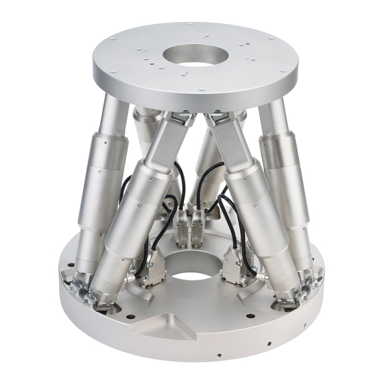
- Page 16 3 Product Description 3.3 Product View Figure 1: Product view Moving platform Strut Panel plug for power supply cable Socket for data transmission cable Base plate Version: 1.1.0 MS202E H-850 Hexapod Microrobot...
- Page 17 3 Product Description 3.4 Scope of Delivery The following table contains the scope of delivery of the Hexapod. The scope of delivery of the Hexapod controller is listed in the user manual of the Hexapod controller. For the scope of delivery of the cable set that belongs to the Hexapod system, see the listing of the standard cable sets in "Model Overview"...
- Page 18 3 Product Description 3.5 Accessories Order Number Description C-887.A20 Hexapod cable set 20 m, consisting of: Name Length Item ID Line driver box for data transmission cable, controller- C030B0011 side C030B0012 Line driver box for data transmission cable, Hexapod- side Short data transmission cable MDR68 to MDR68 1:1;...
- Page 19 3 Product Description 3.6 Technical Features 3.6.1 Struts The Hexapod has six adjustable-length struts. Each strut carries out linear motions. Each set of settings of the six struts defines a position of the moving platform in six degrees of freedom (three translational axes and three rotational axes). Each strut is equipped with the following components: ...
- Page 20 3 Product Description 3.6.4 Motion The platform moves along the translational axes X, Y and Z and around the rotational axes U, V and W. Figure 2: XYZ coordinate system and rotations to the rotation coordinates U, V and W. The coordinate system is depicted above the platform for better clarity.
- Page 21 3 Product Description INFORMATION The dimensional drawing (p. 53) contains the following: Alignment of the XYZ coordinate system Position of the pivot point after the reference move, when the standard settings of the Hexapod controller are used Example: Consecutive rotations INFORMATION For a clearer view, the figures have been adapted as follows: ...
- Page 22 3 Product Description 2. The V axis is commanded to move to position –10. The rotation takes place around rotational axis V, which was tilted during the previous rotation. The rotation around the V axis tilts the rotational axes U and W. Figure 4: Rotation around the V axis Platform in reference position Platform position: U = 10, V = –10 (U and V parallel to the platform level)
- Page 23 3 Product Description 3. The W axis is commanded to move to position 10. The rotation takes place around the rotational axis W, which was tilted during the previous rotations. The W axis is always vertical to the platform level. The rotation around the W axis tilts the rotational axes U and V.
- Page 25 INFORMATION When handling the vacuum version of the Hexapod, attention must be paid to appropriate cleanliness. At PI, all parts are cleaned before assembly. During assembly and measurement, powder-free gloves are worn. Afterwards, the Hexapod is cleaned once again by wiping and shrink-wrapped twice in vacuum-compatible film.
- Page 26 5. Hold the Hexapod by the transport lock and take it out of the foam insert. 6. Compare the contents against the items covered by the contract and against the packing list. If parts are incorrectly supplied or missing, contact PI immediately.
- Page 27 5 Installation Installation In this Chapter General Notes on Installation ..................23 Determining the Permissible Load and Working Space ..........24 Attaching the snap-on ferrite suppressor ..............25 Grounding the Hexapod ....................26 Mounting the Hexapod on a Surface ................26 Affixing the Load to the Hexapod ................
- Page 28 5 Installation INFORMATION The optionally available PIVeriMove software for collision checking can be used to mathematically check possible collisions between the Hexapod, the load and the environment. The use of the software is recommended when the Hexapod is located in a limited installation space and/or operated with a spatially limiting load. For details regarding the activation and configuration of the PIVeriMove software for collision checking, see Technical Note C887T0002 (included in the scope of delivery of the software).
- Page 29 5 Installation 5.3 Attaching the snap-on ferrite suppressor Figure 7: Power supply cable of the Hexapod with snap-on ferrite suppressor Power supply cable of the Hexapod Snap-on ferrite suppressor 000015165 Connector M 12 (for connection to the controller) INFORMATION The snap-on ferrite suppressor 000015165 is included in the scope of delivery of the Hexapod system.
- Page 30 5 Installation 5.4 Grounding the Hexapod The Hexapod is not grounded via the power supply cable. If a functional grounding is required for potential equalization: 1. Connect the base plate to the grounding system: − For connection, use the supplied accessories (p. 13) and the M4 hole with an 8 mm depth (p.
- Page 31 5 Installation Figure 8: Mounting holes in the base plate Prerequisite You have read and understood the General Notes on Installation (p. 23). Tools and accessories Allen wrench 5.0 and six of the supplied screws (p. 13). Optional: two locating pins for easy alignment of the Hexapod, suitable for holes with Ø...
- Page 32 5 Installation Mounting the Hexapod 1. Make the necessary holes in the surface − Six M6 threaded holes for mounting with M6x30 screws − Optional: Two locating holes with Ø 8 mm H7 to accommodate locating pins The arrangement of the six mounting holes as well as the two locating holes in the base plate of the Hexapod can be found in the dimensional drawing (p.
- Page 33 5 Installation NOTICE Screws that are too long! The Hexapod can be damaged by excessively long screws. When selecting the screw length, observe the thickness of the moving platform or the depth of the mounting holes (p. 53) together with the load to be mounted. ...
- Page 34 5 Installation Prerequisites You have read and understood the General Notes on Installation (p. 23). You have determined the permissible load and the working space of the Hexapod (p. 24). You have designed the load and the environment of the Hexapod so that the permissible load of the Hexapod is observed and no collisions can occur.
- Page 35 5 Installation 5.7 Connecting the Cable Set to the Hexapod 5.7.1 Connecting the C-887.A03 Standard Cable Set Prerequisites The cable set is not connected to the Hexapod controller. Tools and accessories Cable set C-887.A03 that belongs to the Hexapod system (p. 10) Connecting the C-887.A03 standard cable set to the Hexapod 1.
- Page 36 5 Installation 5.7.2 Connecting the C-887.V02 Standard Cable Set for Vacuum Versions Figure 10: Dimensions of the vacuum feedthrough for data transmission (4668) (dimensions in mm) 4 holes 45°xØ6 for M3 countersunk screw Version: 1.1.0 MS202E H-850 Hexapod Microrobot...
- Page 37 5 Installation Prerequisites The cable set is not connected to the Hexapod controller. Tools and accessories Cable set C-887.V02 that belongs to the Hexapod system (p. 10) Suitable tools for installing the vacuum feedthrough Installing vacuum feedthroughs 1.
- Page 38 5 Installation Figure 11: Connection diagram for C-887.V02 standard cable set for vacuum versions K060B0112 Power supply cable on the air side, M12m to M12f, 3 m K040B0092 Data transmission cable on the air side, HD Sub-D 78f to MDR68m, 3 m C887B0002 Vacuum feedthrough for power supply, LEMO 2-pin to M12m 4668...
- Page 39 5 Installation Figure 12: Connection diagram of cable set with line driver boxes Line driver box for data transmission cable, controller-side Line driver box for data transmission cable, Hexapod-side Short data transmission cable MDR68 to MDR68 1:1 (3 m) Long data transmission cable MDR68 to MDR68 1:1 Power supply cable for line driver box, with M12 coupling/M12 connector Power supply cable for Hexapod, with M12 coupling/M12 connector ...
- Page 41 6 Start-Up Start-Up In this Chapter General Notes on Start-Up ..................37 Starting Up the Hexapod System ................38 6.1 General Notes on Start-Up CAUTION Risk of crushing by moving parts! There is a risk of minor injuries caused by crushing which can occur between the moving parts of the Hexapod and a stationary part or obstacle.
- Page 42 6 Start-Up NOTICE Damage from collisions! Collisions can damage the Hexapod, the load to be moved, and the environment. Make sure that no collisions between the Hexapod, the load to be moved and the environment are possible in the work space of the Hexapod. ...
- Page 43 7 Maintenance Maintenance In this Chapter Carrying out a Maintenance Run ................. 39 Packing the Hexapod for Transport ................40 Cleaning the Hexapod ....................43 NOTICE Damage due to improper maintenance! The Hexapod can become misaligned as a result of improper maintenance. The specifications can change as a result (p.
- Page 44 7 Maintenance 7.2 Packing the Hexapod for Transport NOTICE Impermissible mechanical load! An impermissible mechanical load can damage the Hexapod. Only send the Hexapod in the original packaging. Only hold the Hexapod by the transport lock or the base plate. INFORMATION The figures in the following section show an H-840 Hexapod.
- Page 45 7 Maintenance Figure 13: Transport lock on the moving platform Transport lock Moving platform Plastic flat washer 3. Position the transport lock (1) on the Hexapod so that the holes in the braces of the transport lock are above the corresponding holes in the moving platform (2) and the base plate of the Hexapod (see figures in "Unpacking"...
- Page 46 7 Maintenance Figure 14: Transport lock on the base plate 6. Fasten the transport lock with 4 screws (M6x20) on the side of the base plate (see figure). 7. Pack the Hexapod in a plastic foil to protect it against dirt. 8.
- Page 47 7 Maintenance 7.3 Cleaning the Hexapod Prerequisites You have disconnected the Hexapod from the controller. Cleaning the Hexapod Do not use any organic solvents. Only when the Hexapod is not used in vacuum: When necessary, clean the surfaces of the Hexapod with a cloth slightly dampened with a mild cleanser or disinfectant.
- Page 49 8 Troubleshooting Troubleshooting Problem Possible Causes Solution Check the data transmission Unexpected Cable broken Hexapod and power supply cables. Connector or behaviour. Replace the cables by cables of soldered joints the same type and test the loosened function of the Hexapod.
- Page 51 9 Customer Service Customer Service For inquiries and orders, contact your PI sales engineer or send us an e-mail (mailto:info@pi.ws). If you have questions concerning your system, have the following information ready: Product codes and serial numbers of all products in the system ...
- Page 53 10 Technical Data 10 Technical Data In this Chapter Specifications ......................49 Ambient Conditions and Classifications ..............52 Dimensions ........................53 Pin Assignment ......................55 10.1 Specifications 10.1.1 Data Table H-850.H1x H-850.G1x Unit Tolerance for higher loads and for higher velocity holding forces and precision X, Y, Z, θ...
- Page 54 10 Technical Data Max. velocity X, Y, Z mm/s Max. velocity θ , θ , θ mrad/s Typ. velocity X, Y, Z mm/s Typ. velocity θ , θ , θ mrad/s Mechanical properties Stiffness X, Y N/µm Stiffness Z N/µm Load (base plate horizontal / any 250 / 50 50 / 20...
- Page 55 10 Technical Data 10.1.3 Specifications for Vacuum-Compatible Versions H-850.HV H-850.GV Unit Tolerance Motion and positioning Min. incremental motion X, Y µm typ. Min. incremental motion Z µm typ. Min. incremental motion θX, θY, θZ* µrad typ. Repeatability Z ±2 ±2 µm typ.
- Page 56 10 Technical Data Bearing Stainless steel Drivetrain elements Stainless steel (drive screw) Electrical components Cable insulation: Teflon (PTFE, FEP) Shrink tubing: Kynar, PTFE Solder: Sn95.5Ag3.8Cu0.7 Connectors: AMP HD20, Lemo PCB's (adapter board, limit switch board, PWM board): sealed with vacuum- compatible Torr seal Grease Molykote HP-300, Klüber Barrierta L55/2...
- Page 57 10 Technical Data 10.3 Dimensions All figures show the Hexapod in the reference position. Dimensions in mm. Note that the decimal places are separated by a comma in the drawings. Figure 15: H-850 Hexapod front view (dimensions in mm) The (0,0,0) coordinates refer to the origin of the XYZ coordinate system. When the default settings of the Hexapod controller are used and the Hexapod is in the reference position, the pivot point is located at the origin of the XYZ coordinate system.
- Page 58 10 Technical Data Figure 16: H-850 Hexapod top view (dimensions in mm) Version: 1.1.0 MS202E H-850 Hexapod Microrobot...
- Page 59 10 Technical Data 10.4 Pin Assignment 10.4.1 Power Supply Connection Not for vacuum versions: Power supply via 4-pin, A-coded M12 panel plug Function 24 V DC 24 V DC Only for vacuum versions: power supply via 2-pin LEMO panel plug, male, type ECJ.1B.302.CLD Function 24 V DC 10.4.2 Data Transmission Connection...
- Page 60 10 Technical Data Pin assignment Version: 1.1.0 MS202E H-850 Hexapod Microrobot...
- Page 61 Instrumente (PI) GmbH & Co. KG ensures environmentally correct disposal of old PI equipment that was first put into circulation after 13 August 2005, free of charge. If you have old PI equipment, you can send it postage-free to the following address: Physik Instrumente (PI) GmbH & Co. KG Auf der Römerstr.
- Page 63 12 Glossary 12 Glossary Work space The entirety of all combinations of translations and rotations that the Hexapod can approach from the current position is referred to as the work space. The work space can be limited by the following external factors: ...
- Page 64 12 Glossary The following example figures of the H-810 Hexapod show that the XYZ coordinate system does not move along with motions of the platform. Figure 17: H-810 Hexapod in the reference position. Cable outlet Version: 1.1.0 MS202E H-850 Hexapod Microrobot...
- Page 65 12 Glossary Figure 18: H-810 Hexapod, the platform of which has been moved in X. Cable outlet H-850 Hexapod Microrobot MS202E Version: 1.1.0...
- Page 67 13 Appendix 13 Appendix In this Chapter Explanations of the Performance Test Sheet .............. 63 EC Declaration of Conformity ..................64 13.1 Explanations of the Performance Test Sheet The Hexapod is tested for the positioning accuracy of the translational axes before delivery.
- Page 68 13 Appendix 13.2 EC Declaration of Conformity Version: 1.1.0 MS202E H-850 Hexapod Microrobot...
Need help?
Do you have a question about the H-850 Series and is the answer not in the manual?
Questions and answers