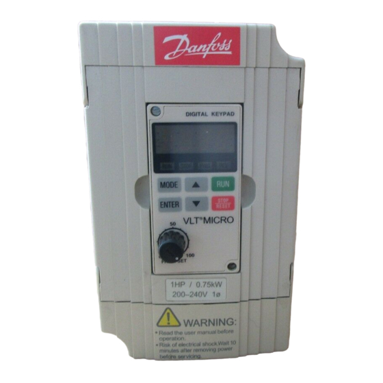
Danfoss VLT MICRO Manual
Adjustable frequency drive
Hide thumbs
Also See for VLT MICRO:
- User manual (113 pages) ,
- Quick manual (31 pages) ,
- Programming manual (74 pages)
Table of Contents
Advertisement
Getting Started ................................................................................. 3
Receiving, Inspection, and Storage .................................................. 4
Nameplate Information ..................................................................... 4
General Technical Data .................................................................... 5
Specifications ................................................................................... 8
External Parts and Labels ................................................................ 9
Installation Requirements ............................................................... 10
Wiring ............................................................................................. 11
Installation without RFI-filter ............................................................ 12
EMC-correct installation with RFI-filter ............................................. 13
Use of EMC compliant cables ......................................................... 14
Earthing of screened/armoured control cables ................................ 15
Control Terminal Designations (Factory Settings) ............................. 16
Safety Precautions ......................................................................... 17
Digital Keypad/Display Features ...................................................... 19
Quick Set-up .................................................................................. 21
Operation ....................................................................................... 23
Description of Parameters .............................................................. 25
Summary of Parameters ................................................................. 69
Troubleshooting and Fault Information ............................................. 76
Appendix A Dimensions ..................................................................................... 80
Appendix B Accessories .................................................................................... 84
Appendix C CE Labeling .................................................................................... 86
Appendix D Serial Communication ..................................................................... 88
Danfoss can accept no responsibility for possible errors in catalogs, brochures and other printed material. Danfoss reserves the right
to alter its products without notice. This also applies to products already on order provided that such alterations can be made without
subsequential changes being necessary in specifications already agreed.
Document Version Number 6.0
Software Version M+
Table of Contents
VLT is a registered Danfoss trade mark
1
® ® ® ® ®
VLT
MICRO
Advertisement
Table of Contents


Need help?
Do you have a question about the VLT MICRO and is the answer not in the manual?
Questions and answers
hola, tengo un inversor de hercios 176F7330 de la marca danfoss y se le daño una resistencia, esta exploto y no puedo ver su valor lo que me impide cambiarla, lo que quiero preguntar es si es posible que me ayuden dando algun diagrama o información en el cual indique cual es el valor de la resistencia en homs y cuantos de cuantos wats debe ser